
 Open Access Article
 This Open Access Article is licensed under a
 Creative Commons Attribution 3.0 Unported Licence
Enhanced electrocatalytic hydrogen generation from water via cobalt-doped Cu2ZnSnS4 nanoparticles†
Renuka V. Digraskar a,
Vijay S. Sapnera,
Shankar S. Narwadea,
Shivsharan M. Malia,
Anil V. Ghuleb and
Bhaskar R. Sathe*a
a,
Vijay S. Sapnera,
Shankar S. Narwadea,
Shivsharan M. Malia,
Anil V. Ghuleb and
Bhaskar R. Sathe*a
aDepartment of Chemistry, Dr Babasaheb Ambedkar Marathwada University, Aurangabad 431004, Maharashtra, India. E-mail: bhaskarsathe@gmail.com
bDepartment of Chemistry, Shivaji University, Kolhapur, Maharashtra, India
First published on 4th June 2018
Abstract
Herein, we adopted a novel noble metal-free Co-doped CZTS-based electrocatalyst for the hydrogen evolution reaction (HER), which was fabricated using a facile, effective, and scalable strategy by employing a sonochemical method. The optimized Co-doped CZTS electrocatalyst shows a superior HER performance with a small overpotential of 200 and 298 mV at 2 and 10 mA−1, respectively, and Tafel slope of 73 mV dec−1, and also exhibits excellent stability up to 700 cycles with negligible loss of the cathodic current. The ease of synthesis and high activity of the Co-doped CZTS-based cost-effective catalytic system appear to be promising for HER catalysis.
1. Introduction
Intensification of the conflict caused by energy security with declining natural energy reserves and the increasing environmental problems together with the urge for the development of modern society have created a huge demand for futuristic renewable and environmentally friendly energy sources. Hydrogen (H2), as an ideal clean energy carrier, is proposed to be a major energy resource for the future world.1 Currently, the traditional methods for the large-scale production of H2 involve the release of a large amount of CO2, high energy consumption and multistep and costly processes such as natural gas reforming and gasification of coal and petroleum coke.2 Thus, considerable efforts have been directed towards the sustainable production of H2 from water electrolysis as an emerging clean-energy technology.3 Therefore, efficient cathode materials are needed to reduce the overpotential and improve the efficiency of the hydrogen evolution reaction (HER). Currently, expensive platinum (Pt) and Pt-based electrocatalysts are the most effective and electrochemically stable catalysts commonly used in the HER.4 Unfortunately, their scarcity and high cost limit their utilization on a large-scale for commercial applications. Thus, it is crucial and a key challenge to develop earth-abundant and inexpensive noble metal-free catalysts that possess good activity with high stability for the HER. Recently, many potential alternatives such as transition-metal dichalcogenides,5,6 carbides,7,8 phosphides,9 boride10 and nitrides11 have been reported as efficient electrocatalysts for the HER. Among them, transition-metal dichalcogenides (TMDs), i.e. MoS2, CoS2, and WS2, have attracted special attention due to their earth-abundant nature and promising properties as HER electrocatalysts. However, one of the challenges with layered dichalcogenide electrocatalysts is their poor electrical conductivity and small number of active sites, which are limited only to the edges, although some are reported to convert their thermodynamically favoured semiconducting phase to a metastable metallic polymorph.9,12–14 Thus, Tan et al. reported the non-layered metal dichalcogenide CoS2 having an evident advantage over the layered metal dichalcogenides due to its conducting nature.9 In our previous work, we revealed that CZTS electrocatalysts show excellent HER activity, and thus more efforts have been made to further improve their HER activity. Interestingly, doping is one of the best strategies to further improve the catalytic performance. Several doped electrocatalysts have been reported, for instance, Liang et al. demonstrated an Fe-promoted MoP catalyst for enhanced HER performance compared to MoP.15 Liu et al. reported that an FeP/NCNT hybrid exhibited higher HER activity and stability than FeP NPs.16 Gao et al. reported N-doped WS2 nanosheets, which exhibit high electrocatalytic activity.17 Wang et al. demonstrated that an Ni-doped MoS2 catalyst shows excellent HER activity compared to pure MoS2.18 More interestingly, the current research in this area is focused on using transition metals (Fe, Co, Ni, Cu, Cr, and Zn) doped with boride,10 phosphide,19 carbide,20 and chalcogenide (S and Se), such as MoS2, WS2, and FeS2,21–24 which have been found to be highly efficient catalysts for the HER. However, their preparation requires a gas chamber, costly and harmful chemicals, and very careful handling, thus prompting researchers to find cheaper alternatives. Nevertheless, to date, reports on the doping effect on the catalytic performance of Co-CZTS hydrogen evolution hybrid catalysts are rare. Based on the above research progress and corresponding HER studies, herein, we investigate improving the performance of the HER with the chalcogenide Cu2ZnSnS4 (CZTS) successfully doped with Co, which has a low cost, high earth abundance, small size, high current density and stability even in harsh acidic conditions and is promising for the HER by water splitting.2. Experimental section
2.1 Chemicals
Copper chloride (CuCl2·2H2O, 98%), zinc chloride (ZnCl2·2H2O, 96%), tin chloride (SnCl2·2H2O, 98%), thioacetamide (TAA), cobalt chloride (CoCl2·6H2O), 2-methoxyethanol, monoethanolamine (MEA) and absolute ethanol of AR grade were used for the sonochemical synthesis of Co-doped CZTS nanoparticles. All the chemicals were procured from Sigma Aldrich and were used as received without any further purification.2.2 Synthesis of Co-doped CZTS nanoparticles
Initially, the sol was prepared with the Cu![[thin space (1/6-em)]](https://www.rsc.org/images/entities/char_2009.gif) :Zn:Sn:TAA ratio of 2:1:1:4 using the respective salt solutions. 1 M of CuCl2 was dissolved in 100 mL of 2-methoxyethanol under vigorous stirring for 30 min followed by the addition of 0.5 M ZnCl2 and stirring for 15 min. Then, 0.5 M SnCl4 was added with constant stirring for 15 min to obtain a clear solution. To this solution, 2 M TAA and an appropriate amount of monoethanolamine were added under continuous and vigorous stirring until the solution turned dark brown. Further, controlled doping was carried by the addition of 5 wt% CoCl2 (doping amount) to this solution, which was then subjected to ultrasonication in an ultrasonic bath (40 kHz, 40 W) for 1.5 h to achieve a black precipitate. The precipitate was repeatedly washed using absolute ethanol to remove excess TAA and other counter ions and then annealed at 170 °C (decomposition temperature of metal–TAA complex) for 2 h.25 This as-synthesized Co-doped CZTS nanoparticles were further characterized and tested as an electrocatalyst for the HER. Interestingly, the electrocatalytic studies towards the water splitting reactions of the sonochemically synthesized CZTS nanoparticles are considered a point of interest in this work.
:Zn:Sn:TAA ratio of 2:1:1:4 using the respective salt solutions. 1 M of CuCl2 was dissolved in 100 mL of 2-methoxyethanol under vigorous stirring for 30 min followed by the addition of 0.5 M ZnCl2 and stirring for 15 min. Then, 0.5 M SnCl4 was added with constant stirring for 15 min to obtain a clear solution. To this solution, 2 M TAA and an appropriate amount of monoethanolamine were added under continuous and vigorous stirring until the solution turned dark brown. Further, controlled doping was carried by the addition of 5 wt% CoCl2 (doping amount) to this solution, which was then subjected to ultrasonication in an ultrasonic bath (40 kHz, 40 W) for 1.5 h to achieve a black precipitate. The precipitate was repeatedly washed using absolute ethanol to remove excess TAA and other counter ions and then annealed at 170 °C (decomposition temperature of metal–TAA complex) for 2 h.25 This as-synthesized Co-doped CZTS nanoparticles were further characterized and tested as an electrocatalyst for the HER. Interestingly, the electrocatalytic studies towards the water splitting reactions of the sonochemically synthesized CZTS nanoparticles are considered a point of interest in this work.
2.3 Structural and morphological characterizations
The product was analyzed via Fourier transform infrared spectroscopy (FTIR). Its phase and structure were characterized using X-ray diffraction (XRD, Siemens D-5005 diffractometer) equipped with an X-ray tube (Cu Kα; λ = 1.5418 nm, 40 kV, 30 mA, with a step size of 0.01°). X-ray photoelectron spectroscopy (XPS) on a SPECS HSA-3500 with a monochromatic Al Kα X-ray radiation X-ray source and hemispherical analyser was used to investigate the elemental states of the sample. The BET surface area of the CZTS powder-based catalyst was determined via N2 adsorption at 77 K and isotherm measurements at 77.3 K using a Quantachrome NovaWin© 1994–2012, Quantachrome Instruments v11.02. Raman spectroscopy was performed using a Raman optical microscope, Seki Technotron Corp. Tokyo with a 532 nm laser. The electrochemical and electrocatalytic studies were performed using an electrochemical workstation (CHI-Instrument 660E, USA) with a three-electrode system.2.4 Electrochemical measurements
The electrochemical HER activity of the catalysts was tested by cyclic voltammetry (CV), linear sweep voltammetry (LSV) and electrochemical impedance spectroscopic (EIS) analysis. The measurements were performed on an electrochemical workstation (CHI-660E) using a three-electrode system with a modified glassy carbon electrode (GCE; 3 mm in dia.) as the working electrode, and saturated calomel electrode (SCE) and platinum wire as the reference and counter electrodes, respectively. Prior to use, the GCE was polished with 1 μm, 0.3 μm and 0.05 μm alumina powder, respectively, followed by sonication in deionized water and methanol for 5 min each. For the fabrication of the working electrode, the catalyst ink was prepared by dispersing 5.0 mg of catalyst into a mixed solvent containing 100:1 of isopropanol:Nafion (5 wt%) solution and sonicating the mixture for ∼30 min to form a homogeneous ink. Afterwards, 10 μL (0.41 mg loading normalized to current density) of the catalytic ink was loaded onto the GCE and dried naturally at RT. Cyclic voltammetry (CV) and linear sweep voltammetry (LSV) were conducted in 0.5 M aqueous H2SO4 electrolytic solutions. All the results are reported with respect to the reversible hydrogen electrode (RHE) in 0.5 M H2SO4, where E (RHE) = E (SCE) + 0.244 V. Electrochemical impedance spectroscopy (EIS) measurements were carried out from 1000000 Hz to 0.002 Hz at a slightly higher onset potential (−0.21 V vs. RHE).
3. Results and discussion
Scheme 1 shows a schematic of the synthesis of the Co-doped CZTS nanoparticles. FT-IR spectroscopy is usually employed to probe the various functional groups and inorganic and organic species and their inter- and intra-binding in samples. Thus, the undoped and Co-doped CZTS nanostructured samples were characterized via FT-IR spectroscopy for comparison in the spectral range of 400–4000 cm−1, as shown in Fig. 1(a). The spectra of the undoped and Co-doped CZTS samples show a common broad band at 3440 cm−1, which is attributed to the O–H stretching vibration,26 while the band at 1020 cm−1 corresponds to the C–S stretching. The bands at 1430 and 1650 cm−1 are due to the coupled vibrations of the C–N stretching and N–H bending in the precursor complex, respectively.27 The band at 2360 cm−1 is attributed to the S–H thiol functionality, which is in agreement with the literature value.28 Moreover, there are no obvious differences between the doped and undoped samples, suggesting that no new bonds are formed in the doped sample in the IR frequency range.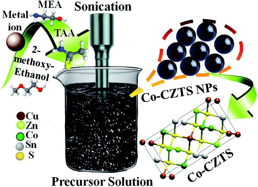 | ||
| Scheme 1 Schematic illustration of the synthetic process for the Co-doped CZTS NPs. | ||
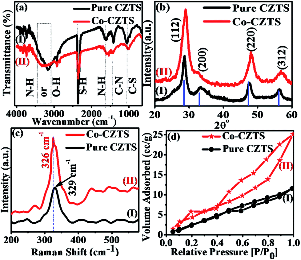 | ||
| Fig. 1 Superimposed (a) FTIR, (b) XRD and (c) Raman spectra and (d) BET curves of CZTS (I) and Co-doped CZTS (II). | ||
Fig. 1(b) shows the representative superimposed powder XRD patterns of the CZTS (I) and Co-doped CZTS (II) nanoparticles. The diffraction peaks in the spectra of both samples are indexed to the kesterite structure of CZTS, and the lattice parameters were calculated to a = 5.399 Å and c = 10.873 Å for pure CZTS and a = 5.396 Å and c = 10.871 Å for the Co-doped CZTS. These values are consistent with the literature values (a = 5.427 Å and c = 10.848 Å, JCPDS no. 26-0575), thus the samples belong to the I42m space group.29,30 No extraneous peaks are observed, indicating the high purity of the final product. The average crystallite size obtained for the pure CZTS and Co-doped CZTS nanoparticles using the Scherrer equation is 4.0 and 3.2 nm and W–H plot of 5.2 and 4.6 nm, respectively. Significantly, upon doping with Co, a slight contraction in the lattice is observed, resulting in broadening of the diffraction peaks, which is in agreement with the literature.31 Moreover, the Raman and X-ray photoelectron spectroscopy (XPS) measurements give further evidence for the incorporation of Co into the CZTS lattice. Raman spectroscopy is a useful tool for the analysis of the effects of doping on nanomaterials because the incorporation of dopants leads to shifts in the lattice Raman vibrational peak positions. Accordingly, as shown in Fig. 1(c), the Raman spectra of the CZTS (I) and Co-doped (II) CZTS nanoparticles exhibit a strong peak located at 329 cm−1, which is indirect evidence of the formation of CZTS NPs. Moreover, after the doping of Co in CZTS, this peak shifts towards a lower energy of 326 cm−1, which can be attributed to electron molecular vibrational coupling due to the substitution of Co2+ ions in the host lattice or (Zn2+ ions).32 Accordingly, the increased intensity of this mode for the cobalt-doped sample compared to the undoped sample suggests that the Co-doped sample contains a higher density of defects and lattice disorders, which is in agreement with literature.33 It is also important to note that there is no additional peak in the Raman spectra of the CZTS and Co-doped CZTS samples, which further confirms the absence of any spurious (and/or impurity) phases of dopant in the samples according to the literature survey.32 Fig. S1, ESI† presents the X-ray photoelectron spectra (XPS) of the samples, which further support our earlier findings of the incorporation of Co into the host lattice of the Cu2ZnSnS4 nanocrystals, where the cobalt atoms are Co2+ substituting the Zn2+ lattice sites in CZTS. The lower binding energy of the 2p3/2 peak at 778.1 eV by 15.6 eV is attributed to cobalt metal (Co0),34 and the detailed elucidation is presented in the ESI.† As shown in Fig. 1(d), the BET surface area of the Co-doped CZTS is 4.213 m2 g−1, which is slightly higher than the 2.016 m2 g−1 of CZTS due to the smaller particle size, pore-size distribution and pore volume of the undoped sample. The CZTS and Co-doped CZTS nanoparticles exhibited an average pore size of 3.578 and 4.617 nm and pore volume of 0.017 and 0.77 cm3 g−1, respectively. The higher surface area of the doped CZTS suggests it has enhanced electrocatalytic activity.
Fig. 2 shows the morphology of the CZTS nanoparticles before and after Co doping. Fig. 2(a) shows that the undoped CZTS nanoparticles are spherical with a uniform particle size distribution. The circled crystalline particles in Fig. 2(b) show the presence of several small-sized well dispersed CZTS NPs without any agglomeration with a slight difference in population. From the images it is clear that the morphology of CZTS did not change after Co doping. Moreover, (inset in Fig. 2(a) and (b)) the particle size distribution histograms of the pure and Co-doped CZTS nanoparticles, respectively, demonstrate that their average particle size decreased because Co substituted Zn in the lattice sites, which creates defects.35 The particle size distribution was 2.6 ± 0.4 and 2.4 ± 0.1 for the pure CZTS and Co-doped CZTS, respectively, which is relatively lower than that reported for samples synthesized via other methods in the literature.36,37 Significantly, the reduction in particle size after Co doping in CZTS, where Co substituted Zn in the lattice sites, is attributed to the smaller ionic radius of Co2+ (0.72 Å) than that of Zn2+ (0.74 Å), which is in good agreement with the XRD results. Consequently, the substitution of Zn by Co causes a decrease in the lattice constant.32 Accordingly, the fast-Fourier transform (FFT) pattern of the Co-doped CZTS nanoparticles in Fig. 2(c) corresponds to the diffraction spot reflecting the d-spacings of 3.1 and 2.7 Å, which can be indexed to the 112 and 200 planes, respectively. This is in agreement with the XRD analysis shown in Fig. 1(b). Moreover, lattice fringes with the d-spacing of 0.312 and 0.315 nm are also observed for the pure CZTS and Co-doped CZTS, which correspond to the (112) representative plane of CZTS, as shown in Fig. 2(c) and (d), respectively.
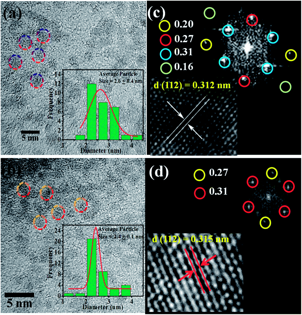 | ||
| Fig. 2 HRTEM image of (a) pure CZTS NPs (2.6 ± 0.1 nm) and (b) Co-doped CZTS NPs (2.4 ± 0.1 nm) (inset shows the particle size distribution plots). Fast-Fourier transform (FFT) patterns of (c) pure CZTS NPs and (d) Co-doped CZTS NPs (inset shows the lattice fringes). | ||
3.1 Electrochemical studies
To demonstrate the enhancement in electrocatalytic activity CZTS after Co doping, cyclic voltammetry (CV) and linear sweep voltammetry (LSV) measurements were carried out and the results compared with that obtained for a Pt catalyst at a scan rate of 50 mV s−1 vs. RHE in 0.5 M H2SO4 solution. As expected, Pt exhibited a much higher HER catalytic performance than the as-synthesised CZTS electrocatalysts.38 After doping Co (low-cost and earth-abundant element) in CZTS, its catalytic activity towards the HER was significantly promoted. Accordingly, Fig. 3(a) presents the superimposed LSV curves of the reference Pt, CZTS and Co-doped CZTS, which shows that the electrocatalytic performance of Co-CZTS is better than that of CZTS with an overpotential of 200 and 298 mV at 2 and 10 mA−1, respectively, and it exhibits a higher current density of −103 mA cm−1−2 (see Scheme S1 in ESI†). A slight change in the features of the LSV curves at a scan rate from 10–100 mV s−1 vs. RHE is observed, which reveals that the catalytic activity of the Co-doped and undoped CZTS NPs toward the HER could be due to controlled mass transfer processes at the electrocatalytic interfaces (see S2 ESI†). Table 1 shows a comparison of the HER performance of the catalysts in the present work with that of other electrocatalysts reported in the literature. From the table, we observe that the low overpotential and Tafel slope of CZTS indicate that it is a promising material for the HER. Since the Tafel slope represents the intrinsic activity of HER catalysts, a smaller Tafel slope value represents a faster HER rate with respect to the increase in overpotential (positive shift). The Tafel slopes derived from the polarization curves were fitted into the Tafel equation (η = a + blogj, where b is the Tafel slope and j is the current density). As shown in Fig. 3(b), the commercial Pt/C catalyst still shows the smallest Tafel slope of ∼36 mV dec−1, which is close to the reported values.39,40 Remarkably, the Co-doped CZTS catalyst exhibits a smaller Tafel slope of 73 mV dec−1 than that of the pure CZTS catalyst (85 mV dec−1), demonstrating its improved HER activity.41–43 Also, the exchange current density of the pure and Co-doped CZTS was 882 and 989 mA cm−2, respectively.
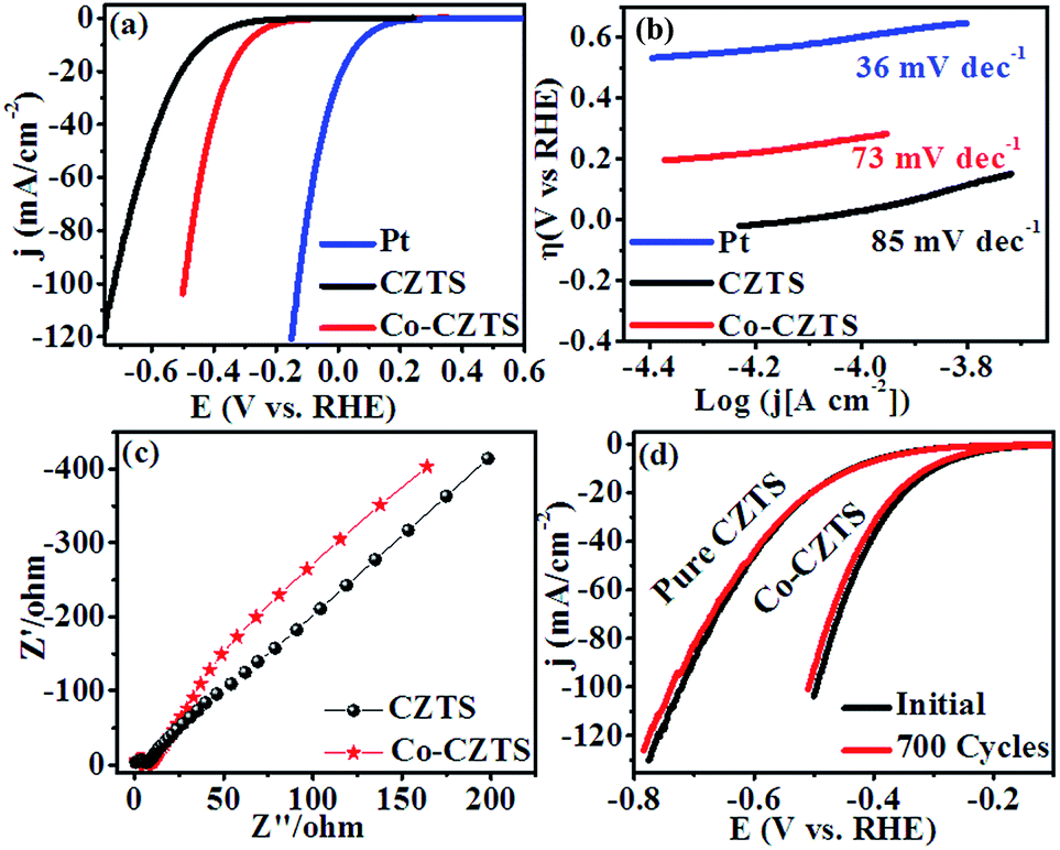 | ||
| Fig. 3 (a) Polarization curves, (b) corresponding Tafel plots and (c) Nyquist plots of the CZTS and Co-doped CZTS NPs. (d) Durability test of Co-CZTS in 0.5 M H2SO4. | ||
| Sr. no. | Materials | Overpotential (mV vs. RHE) | Tafel slope (mV dec−1) | Ref. |
|---|---|---|---|---|
| 1 | F–MoS2 | 380 | 175 | 46 |
| 2 | Co@C | 284 | 129.1 | 47 |
| 3 | Bulk WS2 | 290 | 119 | 48 |
| 4 | ZFO-700 | 377 | 178 | 49 |
| 5 | Pd/C | 264 | 124 | 50 |
| 6 | MWCNTs@Cu | 366 | 109 | 51 |
| 7 | MoP2/Mo | 273 | 69 | 52 |
| 8 | CoTe NTs | 345.4 | 58.7 | 53 |
| 9 | HCL-Ni@C | 440 | 194 | 54 |
| 10 | CoP | 383 | 90 | 55 |
| 11 | Cu/rGO | −430 | 207 | 56 |
| 12 | MoS2 NS | 280 | 90 | 40 |
| 13 | FeP NP | 292 | 86 | 16 |
| 14 | Ni12P5 | 380 | 270 | 57 |
| 15 | N,P-graphene-1 | 420 | 145 | 58 |
| 16 | Mo2C@NPC | 260 | 126.4 | 8 |
| 17 | Co9S8 | 224 | 135 | 59 |
| 18 | Pristine MoS2 | 200 | 91 | 60 |
| 19 | CZTS | 300 | 85 | 25 |
| 20 | Co-CZTS | 200 | 73 | This work |
The significant enhancement in the final HER activity is mainly attributed to the synergistic effect of Co-doping in the CZTS NPs, which further enriched their defect structure and activated some unreactive edge sites.23 We further investigated the HER kinetics of the pure CZTS and Co-doped CZTS catalysts at the electrode/electrolyte interface via electrochemical impedance spectroscopy (EIS). The charge-transfer resistance (Rct) is related to the electrocatalytic kinetics, where a lower value reflects a faster reaction rate, which can be obtained from the diameter of the semicircle in the EIS-Nyquist plot in the low frequency region. Accordingly, as shown in Fig. 3(c), the charge transfer resistance (Rct) of CZTS (6 Ω) is higher than that of Co-CZTS (4 Ω), which indicates its poor conductivity. Thus, the doping of Co significantly improves the electron transport ability of CZTS during the HER process, suggesting that the incorporation of Co increases its electrical conductivity.23,44 Another important criterion for a good electrocatalyst is its current stability for a long period. To assess this, a continuous long-term operation of 700 HER cycles at a 50 mV s−1 scan rate was conducted in 0.5 M H2SO4 for the undoped and Co-doped CZTS catalyst. As shown in Fig. 3(d), a slight loss in activity was observed after 700 cycles, indicating the good durability of the catalysts in acidic media, which is consistent with that reported for CZTS-based systems.45 Furthermore, the turnover frequency (TOF) values were estimated for the HER in a 0.5 M H2SO4 solution using the method of Eric J. Popczun (see ESI† for detailed calculation) at η = 300 mV. The TOF of the Co-doped CZTS was calculated to be about 0.188 s−1, which is much larger than that of pure CZTS and indicates its superior intrinsic HER catalytic activity. Further, to highlight the significance of this report, our results were compared with that obtained in previous reports. The results demonstrate that the Co-doped CZTS electrode exhibits excellent electrocatalytic activity toward the HER (TOF comparison with other electrocatalysts see ESI Table S1†).
4. Conclusion
In summary, a facile sonochemical synthetic strategy has been developed to prepare Co-doped CZTS. XRD, Raman spectroscopy, HR-TEM and XPS were used to achieve a better understanding of the phenomena that occur when Co is incorporated into CZTS. The higher surface area of the Co-doped CZTS indicates its enhanced electrocatalytic activity. With the addition of Co, the HER activity of CZTS was greatly enhanced with a lower overpotential of 163 mV, smaller Tafel slope of 73 mV dec−1, high stability even after 700 cycles and smaller charge transfer resistance. We believe that this work not only provides a low-cost and highly active HER system, but also open a new avenue for exploring the use of metal doping in chalcogenides as attractive catalyst materials for electrocatalytic applications in energy conversion devices.Conflicts of interest
There are no conflicts to declare.Acknowledgements
Author RVD is thankful to DAE-BRNS Mumbai for JRF fellowship. (F. No. 34/20/06/2014-BRNS/21gs), FAST-TRACK DST-SERB, New Delhi (SERB/F/7963/2014-15) and DST_SERB New Delhi research project No. (SERB/F/7490/2016-17) for financial support and Department of Chemistry, Dr Babasaheb Ambedkar Marathwada University, Aurangabad for laboratory facilities.Notes and references
- (a) M. Zeng and Y. Li, J. Mater. Chem. A, 2015, 3, 14942–14962 RSC; (b) S. S. Narwade, B. B. Mulik, S. M. Mali and B. R. Sathe, Appl. Surf. Sci., 2017, 396, 939 CrossRef; (c) X. Zou, J. Su, R. Silva, A. Goswami, B. R. Sathe and T. Asefa, Angew. Chem., Int. Ed., 2014, 126, 4416 Search PubMed; (d) B. R. Sathe, RSC Adv., 2013, 3, 5361–5365 RSC.
- K. Christopher and R. Dimitrios, Energy Environ. Sci., 2012, 5, 6640–6651 Search PubMed.
- (a) Y. Zheng, Y. Jiao, Y. Zhu, L. H. Li, Y. Han, Y. Chen, A. Du, M. Jaroniec and S. Z. Qiao, Nat. Commun., 2014, 5, 3783 CrossRef PubMed; (b) B. R. Sathe, X. Zou and T. Asefa, Catal. Sci. Technol., 2014, 4, 2023 RSC; (c) B. R. Sathe, J. Electroanal. Chem., 2017, 799(15), 609–616 CrossRef.
- G.-R. Xu, J.-J. Hui, T. Huang, Y. Chen and J.-M. Lee, J. Power Sources, 2015, 285, 393–399 CrossRef.
- Y. Wen, Y. D. Xia and S. W. Zhang, J. Power Sources, 2016, 307, 593–598 CrossRef.
- L. Liao, J. Zhu, X. J. Bian, L. N. Zhu, M. D. Scanlon, H. H. Girault and B. H. Liu, Adv. Funct. Mater., 2013, 23, 5326–5333 CrossRef.
- F. Harnisch, G. Sievers and U. Schroder, Appl. Catal., B, 2009, 89, 455–458 CrossRef.
- J. S. Li, Y. Wang, C. H. Liu, S. L. Li, Y. G. Wang, L. Z. Dong, Z. H. Dai, Y. F. Li and Y. Q. Lan, Nat. Commun., 2016, 7, 11204 CrossRef PubMed.
- Y. W. Tan, H. Wang, P. Liu, C. Cheng, F. Zhu, A. Hirata and M. W. Chen, Adv. Mater., 2016, 28, 2951–2955 CrossRef PubMed.
- J. J. Borodzínski and A. Lasia, J. Appl. Electrochem., 1994, 24, 1267–1275 CrossRef.
- T. Bhowmik, M. K. Kundu and S. Barman, ACS Catal., 2016, 6, 1929–1941 CrossRef.
- M. S. Faber, R. Dziedzic, M. A. Lukowski, N. S. Kaiser, Q. Ding and S. Jin, J. Am. Chem. Soc., 2014, 136, 10053–10061 CrossRef PubMed.
- C. H. Mu, H. X. Qi, Y. Q. Song, Z. P. Liu, L. X. Ji, J. G. Deng, Y. B. Liao and F. Scarpa, RSC Adv., 2016, 6, 23–30 RSC.
- D. Voiry, M. Salehi, R. Silva, T. Fujita, M. Chen, T. Asefa, V. B. Shenoy, G. Eda and M. Chhowalla, Nano Lett., 2013, 13, 6222–6227 CrossRef PubMed.
- X. Liang, D. Zhang, Z. Wu and D. Wang, Appl. Catal., A, 2016, 524, 134–138 CrossRef.
- Q. Liu, Z. Pu, A. M. Asiri and X. Sun, Electrochim. Acta, 2014, 149, 324–329 CrossRef.
- D. Gao, C. Sun, J. Zhang, J. Ma, P. Liu, K. Tao and D. Xue, J. Mater. Chem. A, 2016, 29, 11234–11238 Search PubMed.
- D. Wang, X. Zhang, Y. Shen and Z. Wu, RSC Adv., 2016, 6, 16656–16661 RSC.
- Y. Pan, Y. Liu, Y. Lin and C. Liu, ACS Appl. Mater. Interfaces, 2016, 8, 13890–13901 Search PubMed.
- H. Lin, N. Liu, Z. Shi, Y. Guo, Y. Tang and Q. Gao, Adv. Funct. Mater., 2016, 26, 5590–5598 CrossRef.
- H. Wang, C. Tsai, D. Kong, K. Chan, F. Abild-Pedersen, J. Nørskov and Y. Cui, Nano Res., 2015, 8, 566–575 CrossRef.
- D. Merki, H. Vrubel, L. Rovelli, S. Fierro and X. Hu, Chem. Sci., 2012, 3, 2515–2525 RSC.
- H. Zhang, Y. Li, T. Xu, J. Wang, Z. Huo, P. Wan and X. Sun, J. Mater. Chem. A, 2015, 3, 15020–15023 Search PubMed.
- Y. Yang, X.-L. Fan, R. Pan and W.-J. Guo, Phys. Chem. Chem. Phys., 2016, 18, 10152–10157 RSC.
- R. V. Digraskar, B. B. Mulik, P. S. Walke, A. V. Ghule and B. R. Sathe Appl, Surf. Sci., 2017, 412, 475–481 CrossRef.
- J. Wang, P. Zhang, X. Song and L. Gao, RSC Adv., 2015, 5, 1220–1226 RSC.
- T. K. Chaudhuri and D. Tiwari, Sol. Energy Mater. Sol. Cells, 2012, 101, 46–50 CrossRef.
- M. Patel, I. Mukhopadhyay and A. Ray, J. Phys. D: Appl. Phys., 2012, 45, 445103 CrossRef.
- K. Liu, B. Yao, Y. Li, Z. Ding, Z. Xiao, Y. Jiang, G. Wang and D. Pan, New J. Chem., 2017, 41, 685–691 RSC.
- X. Zheng, J. Xu, K. Yan, H. Wang, Z. Wang and S. Yang, Chem. Mater., 2014, 26, 2344–2353 CrossRef.
- P. Chetri, B. Saikia and A. Choudhury, J. Appl. Phys., 2013, 113, 233514 CrossRef.
- (a) C. Xiao, K. Li, J. Zhang, W. Tong, Y. Liu, Z. Li, P. Huang, B. Pan, H. Su and Y. Xie, Mater. Horiz., 2014, 1, 81–86 RSC; (b) M. J. Thompson, K. J. Blakeney, S. D. Cady, M. D. Reichert, J. D. Pilar-Albaladejo, S. T. White and J. Vela, Chem. Mater., 2016, 28, 1668–1677 CrossRef.
- J. Kegel, J. Halpin, F. Laffir, I. M. Povey and M. E. Pemble, CrystEngComm, 2017, 19, 1938–1946 RSC.
- M. Ivill, S. J. Pearton, S. Rawal, L. Leu, P. Sadik, R. Das, A. F. Hebard, M. Chisholm, J. D. Budai and D. P. Norton, New J. Phys., 2008, 10, 065002 CrossRef.
- J. K. Salem, T. M. Hammad, S. Kuhn, M. A. Draaz, N. K. Hejazy and R. Hempelmann, J. Mater. Sci.: Mater. Electron., 2014, 25, 2177–2182 CrossRef.
- N. Jiang, L. Bogoev, M. Popova, S. Gul, J. Yano and Y. Sun, J. Mater. Chem. A, 2014, 2, 19407–19414 Search PubMed.
- B. Flynn, W. Wang, C. H. Chang and G. S. Herman, Phys. Status Solidi A, 2012, 209, 2186–2194 CrossRef.
- K. L. Liu, F. M. Wang, K. Xu, T. A. Shifa, Z. Z. Cheng, X. Y. Zhan and J. He, Nanoscale, 2016, 8, 4699–4704 RSC.
- Y. J. Bai, H. J. Zhang, X. Li, L. Liu, H. T. Xu, H. J. Qiu and Y. Wang, Nanoscale, 2015, 7, 1446–1453 RSC.
- S. Muralikrishna, K. Manjunath, D. Samrat, V. Reddy, T. Ramakrishnappa and D. Nagaraju, RSC Adv., 2015, 5, 89389–89396 RSC.
- D. Hou, W. Zhou, X. Liu, K. Zhou, J. Xie, G. Li and S. Chen, Electrochim. Acta, 2015, 166, 26–31 CrossRef.
- D.-Y. Wang, M. Gong, H.-L. Chou, C.-J. Pan, H.-A. Chen, Y. Wu, M.-C. Lin, M. Guan, J. Yang and C.-W. Chen, J. Am. Chem. Soc., 2015, 137, 1587–1592 CrossRef PubMed.
- Y. Li, H. Wang, L. Xie, Y. Liang, G. Hong and H. Dai, J. Am. Chem. Soc., 2011, 133, 7296–7299 CrossRef PubMed.
- W. Fang, D. Liu, Q. Lu, X. Sun and A. M. Asiri, Electrochem. Commun., 2016, 63, 60–64 CrossRef.
- P. Kush, K. Deori, A. Kumar and S. Deka, J. Mater. Chem. A, 2015, 3, 8098–8106 Search PubMed.
- B. J. Guo, K. Yu, H. L. Li, H. L. Song, Y. Y. Zhang, X. Lei, H. Fu, Y. H. Tan and Z. G. Zhu, ACS Appl. Mater. Interfaces, 2016, 8, 5517–5525 Search PubMed.
- H. B. Zhang, Z. J. Ma, J. J. Duan, H. M. Liu, G. G. Liu, T. Wang, K. Chang, M. Li, L. Shi, X. G. Meng, K. C. Wu and J. H. Ye, ACS Nano, 2016, 10, 684–694 CrossRef PubMed.
- X. Zhao, X. Ma, J. Sun, D. H. Li and X. R. Yang, ACS Nano, 2016, 10, 2159–2166 CrossRef PubMed.
- M. Y. Sun, Y. J. Chen, G. H. Tian, A. P. Wu, H. J. Yan and H. G. Fu, Electrochim. Acta, 2016, 190, 186–192 CrossRef.
- K. Qi, S. S. Yu, Q. Y. Wang, W. Zhang, J. C. Fan, W. T. Zheng and X. Q. Cui, J. Mater. Chem. A, 2016, 4, 4025–4031 Search PubMed.
- F. Li, J. Li, X. Q. Lin, X. Z. Li, Y. Y. Fang, L. X. Jiao, X. C. An, Y. Fu, J. Jin and R. Li, J. Power Sources, 2015, 300, 301–308 CrossRef.
- Z. H. Pu, I. S. Amiinu, M. Wang, Y. S. Yang and S. C. Mu, Nanoscale, 2016, 8, 8500–8504 RSC.
- K. Wang, Z. G. Ye, C. Q. Liu, D. Xi, C. J. Zhou, Z. Q. Shi, H. Y. Xia, G. W. Liu and G. J. Qiao, ACS Appl. Mater. Interfaces, 2016, 8, 2910–2916 Search PubMed.
- L. Fan, P. F. Liu, X. Yan, L. Gu, Z. Z. Yang, H. G. Yang, S. Qiu and X. Yao, Nat. Commun., 2016, 7, 10667 CrossRef PubMed.
- Y. Pan, Y. Lin, Y. Chen, Y. Liu and C. Liu, J. Mater. Chem. A, 2016, 4, 4745–4754 Search PubMed.
- F. Li, L. Zhang, J. Li, X. Lin, X. Li, Y. Fang, J. Huang, W. Li, M. Tian and J. Jin, J. Power Sources, 2015, 292, 15–22 CrossRef.
- Y. Shi and B. Zhang, Chem. Soc. Rev., 2016, 45, 1529–1541 RSC.
- Y. Zheng, Y. Jiao, L. H. Li, T. Xing, Y. Chen, M. Jaroniec and S. Z. Qiao, ACS Nano, 2014, 8, 5290–5296 CrossRef PubMed.
- Y. Pan, Y. Q. Liu and C. G. Liu, Appl. Surf. Sci., 2015, 357, 1133–1140 CrossRef.
- J. Guo, H. Zhu, Y. Sun, L. Tang and X. Zhang, Electrochim. Acta, 2016, 211, 603–610 CrossRef.
Footnote |
| † Electronic supplementary information (ESI) available. See DOI: 10.1039/c8ra01886c |
| This journal is © The Royal Society of Chemistry 2018 |