
 Open Access Article
 This Open Access Article is licensed under a Creative Commons Attribution-Non Commercial 3.0 Unported Licence
Pt-grown carbon nanofibers for detection of hydrogen peroxide†
Noora Isoaho a,
Sami Sainiob,
Niklas Westerb,
Luis Botellod,
Leena-Sisko Johanssonc,
Emilia Peltolaa,
Victor Climentd,
Juan M. Feliud,
Jari Koskinenb and
Tomi Laurila*a
a,
Sami Sainiob,
Niklas Westerb,
Luis Botellod,
Leena-Sisko Johanssonc,
Emilia Peltolaa,
Victor Climentd,
Juan M. Feliud,
Jari Koskinenb and
Tomi Laurila*a
aDepartment of Electrical Engineering and Automation, School of Electrical Engineering, Aalto University, PO Box 13500, 00076 Aalto, Finland. E-mail: tomi.laurila@aalto.fi; Tel: +358 50 341 4375
bDepartment Chemistry and Materials Science, School of Chemical Technology, Aalto University, PO Box 16200, 00076 Aalto, Finland
cDepartment of Bioprocess and Biosystems, School of Chemical Technology, Aalto University, PO Box 16300, 00076 Aalto, Finland
dInstituto de Electroquímica, Universidad de Alicante, Apt. 99, 03080 Alicante, Spain
First published on 3rd April 2018
Abstract
Removal of left-over catalyst particles from carbon nanomaterials is a significant scientific and technological problem. Here, we present the physical and electrochemical study of application-specific carbon nanofibers grown from Pt-catalyst layers. The use of Pt catalyst removes the requirement for any cleaning procedure as the remaining catalyst particles have a specific role in the end-application. Despite the relatively small amount of Pt in the samples (7.0 ± 0.2%), they show electrochemical features closely resembling those of polycrystalline Pt. In O2-containing environment, the material shows two separate linear ranges for hydrogen peroxide reduction: 1–100 μM and 100–1000 μM with sensitivities of 0.432 μA μM−1 cm−2 and 0.257 μA μM−1 cm−2, respectively, with a 0.21 μM limit of detection. In deaerated solution, there is only one linear range with sensitivity 0.244 μA μM−1 cm−2 and 0.22 μM limit of detection. We suggest that the high sensitivity between 1 μM and 100 μM in solutions where O2 is present is due to oxygen reduction reaction occurring on the CNFs producing a small additional cathodic contribution to the measured current. This has important implications when Pt-containing sensors are utilized to detect hydrogen peroxide reduction in biological, O2-containing environment.
1. Introduction
Hydrogen peroxide (H2O2) is a versatile chemical, its use ranging from industrial and medical to household applications. One particular branch of research related to H2O2 is the study of oxygen reduction reaction (ORR), which can be, for example, the cathodic half-cell reaction in polymer electrolyte membrane fuel cells. ORR is also of fundamental importance in corrosion studies. It has been proposed that oxygen can be reduced to water either via direct four electron reduction or via two two-electron steps where H2O2 acts as an intermediate.1 However, some controversy still remains and it has been stated that studying H2O2 oxidation and reduction could bring more insight into ORR as well.2As one of the reactive oxygen species, it is considered one of the radicals linked to aging.3 On the other hand, despite its harmful effects, H2O2 is also acting in carefully monitored signaling pathways in cells.4 Moreover, the function of enzymatic biosensors utilizing certain oxidases is based on electrochemical detection of H2O2 which is one of the products from oxidation of the substrate molecule. Thus, detecting H2O2 accurately and reliably is important in the biomedical field.
Discovery of carbon nanotubes (CNTs) in the early 90's (ref. 5) started widespread interest in the research of various carbon nanomaterials. Carbon is relatively inexpensive and abundant material with large number of allotropes and tunable properties which makes it an ideal option for development of sensor applications.6 Moreover, carbon materials often have functional groups that allow immobilization of enzymes via covalent bonds making them good platforms for enzymatic biosensors. Different carbon materials can also be combined to give new hybrid materials with enhanced properties. For example, CNTs grown from tetrahedral amorphous carbon (ta-C) have been shown to induce selectivity between oxidation of dopamine and ascorbic acid, which would otherwise give overlapping signals in the voltammograms.7 In addition to CNTs, carbon nanofibers (CNFs) can also be grown from ta-C. Growing the CNFs from another carbon material, here ta-C, offers an additional carbon source and changes the fiber morphology from bamboo-like to stacked platelet-like structure.8
Ni is often utilized as catalyst metal for the growth of CNFs. However, some of the catalyst remains at the tips of the fibers and cannot be completely removed for example by treating the samples with concentrated acid.9 Moreover, when aiming to develop applications for possible future in vivo use in electrochemical sensors, nickel should be avoided as it is a common contact allergen.10 We have previously presented the use of application-specific catalyst layers in fabrication of Pt-containing carbon nanofibers (Pt–CNFs).11 From 10 nm thick Pt layer with underlaying ta-C thin film it is possible to grow CNFs with height up to several hundreds of nanometers. Pt is present in these fibers as a larger particle at the tip and as smaller particles along the length of the fibers. Even though part of the Ti used as adhesion layer was distributed as fine particles in the fibers, it did not visibly affect the electrochemical response. The advantages of this novel hybrid carbon nanomaterial include the well-ordered structure and control over the location where fibers are grown, which is important from the device fabrication point of view. The preliminary results showed that this novel hybrid carbon nanomaterial could be utilized for H2O2 detection. Here, we proceed to the in depth structural and electrochemical characterization of the Pt–CNFs and especially asses the roles of dissolved oxygen and chloride ions on the electrochemical performance. To verify the crucial role of Pt nanoparticles in the electrochemical behavior of the CNFs, carbon nanofibers grown from nanodiamonds were utilized as a metal-free reference.
2. Experimental
2.1. Sample preparation
Samples were prepared on boron doped p-type Si(100) wafers with 0.005 Ω cm resistivity (Siegert, Germany). The wafer was first coated with a 20 nm Ti adhesion layer with direct current magnetron sputtering. Next, 7 nm ta-C was deposited on top of the Ti layer by pulsed filtered cathodic vacuum arc deposition in base pressure below 1.3 × 10⁻⁴ Pa. Before CNF growth 10 nm Pt catalyst layer was deposited also with cathodic arc deposition. More detailed description of the deposition procedures can be found in our earlier publication12 with the difference that here instead of using a gradient function for the deposition, first only carbon was sputtered from one cathode and then only Pt from another cathode. Finally, samples were placed in the cold-wall plasma-enhanced chemical vapor deposition reactor (Aixtron, Black Magic, Germany) and CNF were grown as described in detail in our previous publication.11 In brief, NH3/C2H2 gas mixture (125/30 sccm) was injected to the reactor at growth temperature of 750 °C for 30 minutes. In addition to using Pt as catalyst, nanofibers were also grown from carboxyl functionalized zeta-negative nanodiamonds (NDs, Carbodeon uDiamonds, Carbodeon, Vantaa, Finland) in order to obtain a metal-free reference material for the Pt–CNFs. The concentration of the original water-based ND solution was 5 wt% and it was diluted into 0.05 wt% in ethanol. The NDs were deposited on the silicon chips by spray coating with pressurized air (3.5 bar) as the carrying gas. The distance between the spray gun and samples was 10 cm. Scanning over the samples was repeated 10 times. CNF growth process was the same as for the Pt–CNF samples except for the growth time which was 30 min and temperature which was 600 °C.In addition to the ND–CNFs also 10 nm Pt thin film samples and spherical polycrystalline Pt electrode were utilized for comparison in electrochemical experiments.
For electrochemical experiments (cyclic voltammetry and amperometry) a circular area (varying geometric areas) was defined with PTFE tape. For rotating disk electrode experiments a special holder with radius of 3 mm was utilized.
2.2. Physical characterization
HRTEM samples were prepared by focused ion beam (FIB) milling using polymer ink as filler material. 70–80 nm Pt and Pt–C (FIB deposited) were used to protect the CNFs during sample fabrication. Double aberration-corrected microscope (JEOL 2100, Japan) equipped with an X-ray detector was utilized for high-resolution TEM imaging. Digital recording was performed with a Gatan 4× 4 UltraScan 4000 CCD camera.SEM images were obtained with Zeiss Sigma VP. Sample were mounted on holders (planar and cross-sectional) with double-sided carbon tape and Cu tape. No additional coating was used.
XPS measurements were performed with Kratos AXIS Ultra X-ray photoelectron spectroscope (Kratos Analytical, Manchester, UK) using monochromated Al Kα X-ray irradiation at 100 W. Samples were pre-evacuated in sample transfer chamber overnight. Both survey-spectra and high-resolution spectra of C 1s, O 1s and Pt 4f was collected from three locations per sample. Cellulose filter paper (Whatman) was used as an internal in situ ref. 13 Analysis depth was expected to be <10 nm and area 400 × 800 μm2. CasaXPS software was used for both extracting the elemental atomic percentages from the survey spectra and fitting the C 1s and Pt 4f high-resolution regimes (Shirley-background with assumed Gaussian line shapes). The reported cellulose in situ reference was used for charge correcting the binding energies, where 286.7 eV was assigned for carbon atoms bonded to single oxygen atom.14
2.3. Electrochemical experiments
All electrochemical experiments were performed with either Gamry Reference 600 or 600 + potentiostat (Gamry Instruments) with Ag/AgCl/KCl sat'd reference electrode (Radiometer Analytical) and Pt wire counter electrode. To address the difference in pH some of the results are presented against RHE. The conversion was done by utilizing Nernst equation taking into account solution pH. Rotating disk electrode (RDE) experiments were conducted by using a Radiometer Analytical rotating motor (Model EDI101). Samples used in RDE were examined in SEM before and after the experiments and despite some minor agglomeration the fibers retained their vertical alignment. Amperometric experiments were performed by stepping the potential from 0 V to −0.15 V vs. Ag/AgCl. Between measurements the solution was mixed either with magnetic stirrer or bubbling with N2. The magnetic stirrer was off during the measurement.Unless stated otherwise, the solution were purged with N2 before starting the experiment and gas blanket was used during the measurements. The electrochemical characterization was performed by scanning in 0.15 M H2SO4 (diluted from 95–97% H2SO4, Merck Millipore) at 50 mV s−1. Scanning was also repeated in phosphate buffered saline (PBS, pH 7.4) containing NaCl (137 mM), KCl (2.7 mM), Na2HPO4 (10 mM) and KH2PO4 (1.8 mM) as well as phosphate buffer without chlorides (PBNa, pH 7.2) containing H2NaPO4 (30 mM) and HNa2PO4 (70 mM). Samples were also characterized in 1 mM hexaammineruthenium(III) chloride (Ru(NH3)6Cl3, Aldrich, 98%) in 1 M KCl. H2O2 stock solutions were prepared from 30% H2O2 (Merck KGaA, Germany) by diluting in deionized water.
For comparison, phosphate buffer (PBK, pH 7.2) was also prepared using potassium phosphates instead of sodium phosphates. To assess the effect of pH and adding phosphates a solution containing both 0.1 M H2SO4 and 0.1 M KH2PO4 was prepared (pH 1.3).
3. Results and discussion
3.1. Characterization
The SEM micrographs in Fig. 1 show that the CNFs form a thick forest of fibers with average length of approximately 500 nm. From the top view image (Fig. 1B) it can be seen that the fibers form bundles with some tens of nanometers between them. The catalyst particles are also clearly visible in the SEM micrographs. Especially the top view illustrates the size of the particles varies considerably, possibly partly due to the bundling of the fibers. HRTEM micrographs in Fig. 1C and D show the fibers and the catalyst particles in more detail. Together with the SEM images (Fig. 1A), the HRTEM micrograph in Fig. 1C highlights that the length of the fibers varies from approximately 60 nm to 600 nm. This is somewhat shorter than presented in our previous publication11 where the lengths of the fibers were observed to span from few hundreds of nanometers to even up to micrometer scale. This is explained by the shorter growth period (30 min vs. 60 min) for the sample batch used here as well as the stochastic growth process. It is visible from Fig. 1D that some of the catalyst Pt particles at the tips of the fibers are in fact single crystals. However, as presented in the electrochemical characterization section below, the Pt–CNF show polycrystalline-like behavior when cycled for example in H2SO4, indicating that the particles are not terminated in any preferential orientation. Such lack of preferential orientation might be a consequence of the oxidation and reduction cycles applied during the cleaning procedure.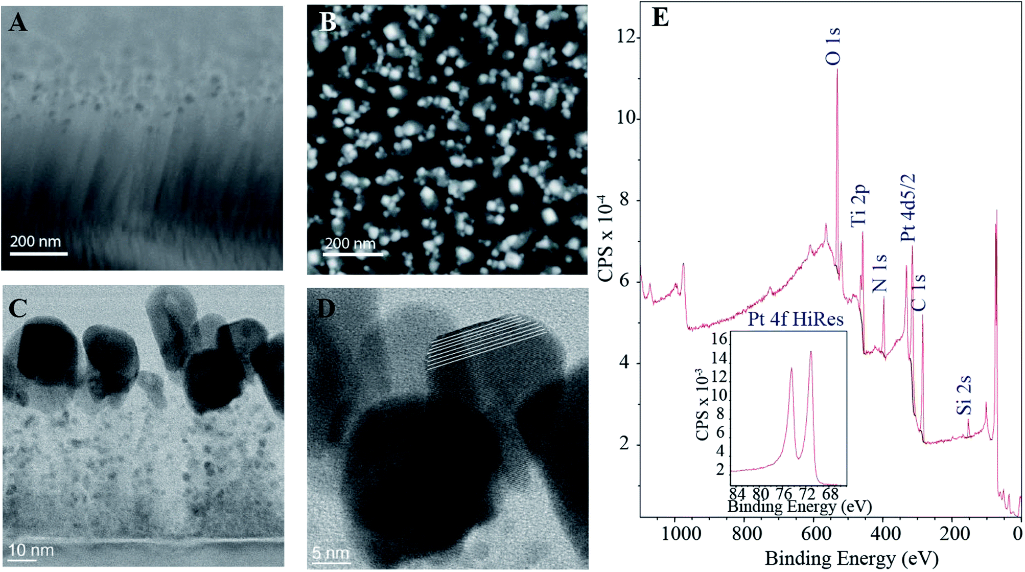 | ||
| Fig. 1 SEM micrographs: tilted cross-sectional (A) and top view (B) of the fibers. The catalyst particles located in the tips are clearly visible in both images. The HRTEM micrographs (C and D) show the fibers and the catalyst particles in more detail. As can be seen from the middle particle in D, some of the catalyst particles are single crystals even though the samples show mostly polycrystalline behavior (the white lines in D have been added to help guide the eye). (E) XPS wide spectrum for Pt–CNFs with the inset showing the high resolution spectrum for the Pt 4f doublet. | ||
The XPS spectra in Fig. 1E further verifies the presence of Pt through the Pt 4f doublet. Moreover, it was estimated from XPS data that the amount of Pt in the samples was 7.0 ± 0.2%. Fitting the Pt 4f peaks (ESI Fig. S1†) showed that approximately 75% of the Pt in the samples is in metallic form and the rest as different Pt oxides. Some estimates on the nature of the oxides is provided in the ESI.† Interestingly the amount of Ti detected by the XPS was 7.2% which is considerably higher than for amorphous carbon films with intrinsic Pt-gradient, where all the Ti utilized as adhesion layer was buried under the thin film.12 We have previously shown that when the Pt catalyst layer is 10 nm in addition to the irregularly shaped Pt particles at the tips the grown fibers have finely distributed Ti along their lengths.11 However, most of the Ti adhesion layer is still intact which has been suggested to be a consequence of thick enough catalyst layer protecting the ta-C film as well as a prerequisite for the proper fiber growth.
3.2. Electrochemical characterization and H2O2 detection
Fig. 2A shows that especially in H2SO4 the Pt features including oxide formation and reduction as well as hydrogen adsorption and desorption are clearly visible. The hydrogen region below 0.4 V vs. RHE has been denoted as the fingerprint for clean polycrystalline Pt and since especially the smaller peak at 0.2 V vs. RHE is only visible on very clean surfaces15 it can be said that despite the dirty initial conditions Pt can be cleaned efficiently by potential cycling. The dirty conditions refer here to the inevitable presence of carbon impurities in the solution – originating from the samples themselves – that could contaminate Pt. On the other hand, in the buffer solutions all the Pt features are still visible but clearly the cleaning effect of potential cycling in this media is less efficient.Samples were also characterized with 1 mM hexaammineruthenium(III) chloride (Ru(NH3)6Cl3, Aldrich, 98%) in 1 M KCl. Pt–CNFs showed reversible electron transfer kinetics: ΔEp increased from 59 mV for 10 mV s−1 to 64 mV for 1 V s−1 (Fig. 2B). As the electron transfer was practically reversible, the electrochemically active surface area was estimated from the data by using Randles–Sevcik equation:
| IP = (2.69 × 10⁵)n2/3AD1/2v1/2C0, | (1) |
 | ||
| Fig. 2 (A) Voltammograms for Pt–CNFs at 50 mV s−1 in PBS, in phosphate buffer and in 0.15 M H2SO4. (B) Electrochemical characterization of the Pt–CNFs in 1 mM Ru(NH3)6Cl3 in 1 M KCl at different scan rates. To take the pH difference into account the graphs in both A and B are presented in RHE scale even though the original measurements were performed against Ag/AgCl/KCl sat'd. Conversion was done by utilizing Nernst equation taking into account solution pH. | ||
We have previously presented initial results that showed that the Pt–CNFs are suitable for amperometric detection of H2O2 in O2-containing environment.11 Fig. 3A shows that when potential is stepped from initial value of 0 V to −0.15 V vs. Ag/AgCl and when H2O2 concentration is increased by intervals of 10 μM between 10 μM and 100 μM and by intervals of 100 μM between 100 μM and 1000 μM (increase in volume was the same throughout the whole region) in non-deaerated PBS there are in fact two separate linear ranges: first from 1 μM to 100 μM with sensitivity of 0.432 μA μM−1 cm−2 and second from 100 μM to 1000 μM with sensitivity of 0.257 μA μM−1 cm−2. The limit of detection was 0.21 μM (S/N = 3). The limit of detection presented here is considerably larger than what we presented for the Pt–CNFs in our previous publication (0.2 nM). On the other hand, the sensitivities for both linear ranges are slightly higher but still in the same range as the one published previously (0.148 μA μM−1 cm−2). The inconsistency between these results could, at least to some extent, arise from the variation between and within sample batches. The growth process of the fibers depends on such parameters as temperature, time period and catalyst layer thickness. In addition, the condition of the growth chamber, i.e. if it has been cleaned recently, can have an effect on the fibers. Finally, the growth process is highly stochastic which affects for example the length and diameter of the fibers (Fig. 1A and C).
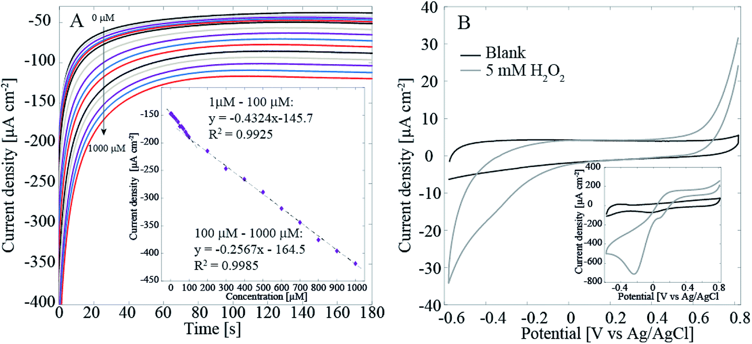 | ||
| Fig. 3 (A) Amperometric detection of H2O2 with the Pt–CNF samples in non-deaerated PBS. The potential was stepped from 0 V to −0.15 V vs. Ag/AgCl for 180 s. The concentration was first increased to 1 μM and then to 5 μM. Between 10 μM and 100 μM the concentration was increase by steps of 10 μM and above 100 μM by steps of 100 μM. The data points were obtained by averaging the current between 0.5 s and 1 s. (B) Cyclic voltammograms recorded at 50 mV s−1 for ND–CNFs in blank and H2O2-containing PBS (deaerated). Inset shows the same measurement for Pt–CNFs. | ||
To verify that the main current here arises from the Pt catalyst particles, we measured the reduction of H2O2 with the Pt-free ND–CNFs for comparison. Fig. 3B shows that even with as high concentration as 5 mM of H2O2 the current density for its reduction is very small (less than 10%) compared to the current density obtained in with Pt–CNFs (Fig. 3B inset). This supports the assumption that it is mainly Pt particles, and not the CNFs, that catalyse the reaction.
Interestingly, when measuring H2O2 in deaerated (O2-free) solutions there is only one linear range from 5 μM to 1000 μM with sensitivity of 0.244 μA μM−1 cm−2 and 0.22 μM limit of detection (results not shown here). Since the only difference between the two experiments was the presence of O2 in the cell, it is assumed that it must contribute to this behavior. In fact, it is well known that Pt is an efficient catalyst for ORR. Another important phenomenon is the effect of Cl− adsorption on ORR and H2O2 reactions of Pt. To test these phenomena with the Pt–CNFs, voltammograms were recorded in O2-saturated PBS containing high concentration of Cl− and chloride-free phosphate buffers (PBK, PBNa) as well as 0.15 M H2SO4 (Fig. 4A shows results only for PBS and PBK since PBNa and 0.15 M H2SO4 were very similar to PBK). It has been previously shown that chlorides strongly inhibit the oxygen reduction reaction.19 For all solutions the current magnitude in the cathodic end is increased considerably indicating the presence of O2 in the solution. However, there is a clear difference for the onset and peak potentials for oxygen reduction between PBS and the other solutions: for example in PBK the current starts to decrease at 0.2 V vs. Ag/AgCl reaching the peak at 0 V whereas for PBS ORR onset is shifted to approximately 0 V and the peak to −0.2 V. As said, the main difference in composition especially between the two phosphate buffers and PBS is the absence/presence of chlorides. PBS contains large amounts of chlorides (approximately 140 mM) which explains the shifting of the peak to −0.2 V vs. Ag/AgCl compared to the blank, N2-saturated solution. For clarity, Fig. 4A shows only the blank for PBK as it was nearly identical with that of PBS. In absence of chlorides (PBNa, PBK and H2SO4) oxygen reduction coincides with Pt oxides reduction as expected.
 | ||
| Fig. 4 (A) Voltammograms for Pt–CNFs in blank (N2-saturated) PBK and O2-saturated PBK and PBS. (B) Voltammograms for polycrystalline Pt in blank (N2-saturated) PBNa and O2-saturated PBNa and PBS. (C) Voltammograms for ND–CNFs in blank (N2-saturated) PBS. (D) Voltammograms for Pt–CNFs in blank and H2O2-containing PBS (non-deaerated). Scan rate in (A–D) was 50 mV s−1. | ||
Fig. 4A also shows that in PBS the current magnitude is increased also at the anodic end of the curve when O2 is present. For the other solutions, the anodic end were comparable to the respective blanks. This is suggested to arise from incomplete ORR, which does not proceed to H2O in chloride-containing solution but actually produces additional H2O2 into the solution, which is then oxidized at anodic potentials above 0.8 V vs. Ag/AgCl. Similar experiment was also tested with a spherical polycrystalline Pt electrode under well-controlled conditions and the results obtained (Fig. 4B) were identical to those of Pt–CNFs. The proposed production of H2O2 was further tested with polycrystalline Pt by reversing the potential at 0.2 V vs. Ag/AgCl to avoid the ORR. There was no extra anodic current compared to the blank curve which supports the suggestion that H2O2 is produced during the ORR (results not showed here). Finally, the experiment was also repeated with ND–CNFs (Fig. 4C). Oxygen is reduced at the cathodic end but the current (density) magnitude from ORR on carbon can be considered negligible and thus the main contribution indeed arises from Pt in the Pt-grown nanofibers. The small cathodic current arising from the ORR at the CNFs themselves and not the Pt catalyst particles provides an additional contribution to the measured currents for small H2O2 concentrations. This additional contribution becomes negligible as soon as the concentration of H2O2 becomes high enough so that the current arising from this process starts to dominate the total current. It is to be noted that the amperometric experiments were conducted at −0.15 V vs. Ag/AgCl which is in the potential range for ORR. Thus, this coupling of two electrochemical processes in O2-containing solutions explains why there are two linear ranges in the non-degassed PBS and not in the N2-purged solution. This is a fact that must be taken into account when results from the literature (see Table 2) are considered.
| Solution | Resistivity (Ω cm) | pH |
|---|---|---|
| H2SO4 | 0.58 | 0.95 |
| PBNa | 1.48 | 7.22 |
| PBK | 1.18 | 7.23 |
| H2SO4 + KH2PO4 | 0.67 | 1.26 |
| PBS | 1.07 | 7.42 |
| Material | EAg/AgCl | LOD (μM) | Sensitivity (μA μM−1 cm−2) | Response time (s) | Linear range (μM) | Reference |
|---|---|---|---|---|---|---|
| Phosphate buffer | ||||||
| Pt-CNT nanocomposites | −0.1 | 1.5 | — | 5 | 5–25![[thin space (1/6-em)]](https://www.rsc.org/images/entities/char_2009.gif) 000 000 |
26 |
| Au/Pt NP-coated CNT/silica nanocables | −0.1 | 0.3 | — | 3.5 | 0.5–1670 | 27 |
| PtNPs on graphene hydbrid nanosheet | 0 | 0.08 | — | 4 | 1–500 | 28 |
| Au–Pt nanowires | 0.045 | 1.5 | 0.1292 | 7 | 20–8380 | 29 |
| Pt NP/MWCNT clusters on screen-printed Au nanofilm | −0.4 | 1.23 | 0.003359/A | 5–2000 | 30 | |
| 1780–16800 |
||||||
| Ultralow Pt-loading Au nanoflowers | 0.09 | 0.006 | 0.003184/A | 0.025–3.45 | 31 | |
| 0.000316/A | 5.91–94.3 | |||||
| Pt/porous graphene on GC | −0.1 | 0.5 | 0.3411 | 3 | 1–1477 | 32 |
| Au@C@Pt nanocomposite on GC | 0 | 0.13 | 0.1447 | 10 | 9–1860 | 33 |
| 0.0801 | 1860–7110 | |||||
| Pd core-PtNDs/PDDA–rGO on GC | 0.018 | 0.027 | 0.6728 | 5 | 5–500 | 34 |
| Au–Pt core@shell NPs | −0.6 | 0.06 | — | 3 | 0.1–1 | 35 |
| Fe@Pt core–shell NPs | −0.355 | 0.75 | 0.2190 | 1 | 2.5–41605 |
36 |
| SiO2 nanorods/APTMS/AuPt | −0.155 | 2.6 | 0.0467 | 5 | 5–72000 |
37 |
| SiO2 nanorods/APTMS/Pt | −0.275 | 0.7 | 0.0608 | 12 | 5–5100 | |
| 0.0127 | 5100–134000 | |||||
| PtNPs | −0.035 | 4.2 | 0.1103 | 3 | 5–58000 |
|
| AuNPs | −0.175 | 5 | 0.0014 | 4 | 5–43000 |
|
| 0.0028 | 43000–77000 |
|||||
|
||||||
| Phosphate buffered saline | ||||||
| Pt–Au NP/titania nanotube array | −0.2 | 10 | 0.00292/A | 10–80 | 38 | |
| Pt–Au NPs/reduced graphene sheets | 0.045 | 0.31 | 0.006168/A | 1–1780 | 24 | |
| a-C/Pt | −0.2 | 0.32 | 0.32 | 0.05 | 50–1000 | 12 |
| Pt–CNFs | −0.15 | 0.21 | 0.432 | 1–100 | This work | |
| 0.257 | 100–1000 | |||||
When cycling the potential of the samples in non-deaerated PBS containing large amounts (<500 μM) of H2O2, an additional peak appeared approximately at −0.2 V vs. Ag/AgCl in the voltammogram (Fig. 4D). Similar peak appeared also in N2-purged solution but only with even higher concentration of H2O2 (1000 μM, see ESI Fig. S3†). It has been stated by Katsounaros et al.2 that at high enough anodic potentials where OH has been adsorbed on Pt, O2 is produced in a non-electrochemical step:
| 2Pt(OH) + H2O2 → 2Pt(H2O) + O2 | (2) |
Thus, even in initially degassed solutions when cycling the potential in a large enough window, O2 originating from added H2O2 can be expected to be present. This means that in addition to hydrogen peroxide redox reactions oxygen reduction is also likely to occur. Moreover, there might be some threshold concentration for O2 since the peak only appears with addition of H2O2 in non-degassed solutions where O2 can be expected to be present initially. This is further supported by the peak only appearing with addition of larger amount of H2O2 in N2-purged PBS (Fig. S3†). It should be noted that the peak does not appear if the upper potential limit is not high enough (>0.5 V vs. Ag/AgCl, results not shown here) which further supports the proposed origin (OH has to be stable on Pt for producing O2).
H2O2 oxidation and reduction were also studied by using RDE. It is shown in Fig. 5 that compared to 0.15 M H2SO4 oxidation and reduction of H2O2 are kinetically hindered in 0.1 M phosphate buffer as higher (lower) potentials are needed for reaching the limiting currents at both anodic and cathodic ends. The solution was prepared without chlorides to avoid the inhibitory effect. One explanation for the apparently slower kinetics could be that the resistivitities for the buffer solutions are higher compared to H2SO4: 1.48 Ω m (PBNa) and 1.18 (PBK) vs. 0.58 Ω m, respectively. In order to compensate this difference in resistivity a post iR correction was run for the PB data presented in Fig. 5 in Echem Analyst software for the ohmic drop (original graphs without post iR correction are presented in the ESI as Fig. S4†). When adding KH2PO4 into H2SO4 the resistivity slightly increased to 0.67 Ω m, which is likely a consequence of the increased pH. Fig. 5 shows that especially the H2O2 reduction is clearly hindered both in PB (iR corrected data) and the mixed solution compared to pure H2SO4. The effect is somewhat larger than what would be expected from the relatively small change in resistivity. On the other hand, hydrogen peroxide is reduced according to eqn (3):
| H2O2 + 2H+ + 2e− ↔ 2H2O | (3) |
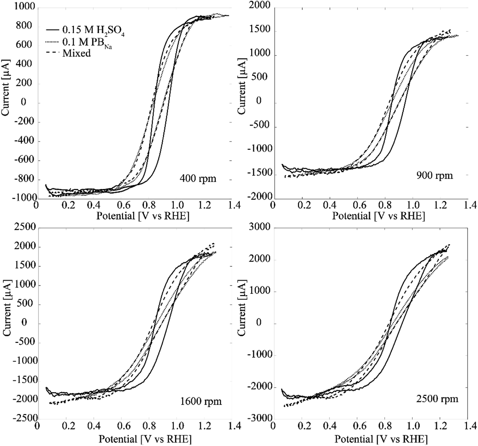 | ||
| Fig. 5 RDE experiments (50 mV s−1) with Pt–CNFs at 400 rpm, 900 rpm, 1600 rpm and at 2500 rpm in 0.15 M H2SO4, PBNa and mixed solution of phosphate buffer and H2SO4 with 5 mM H2O2. To take the pH difference into account the graphs are presented in RHE scale even though the original measurements were performed against Ag/AgCl/KCl sat'd. Conversion was done by utilizing Nernst equation taking into account solution pH. In addition the ohmic drop was compensated for the PBNa by running a post iR correction (Ru = 100 Ω) in Echem Analyst software. | ||
Since the addition of KH2PO4 causes a significant effect in the RDE curve especially in the cathodic end of the transition region, we suggest that this could be related to adsorption of phosphate anions. It has been shown that phosphate species adsorb on polycrystalline as well as Pt (111) and Pt (100) surfaces, with the exact nature of the adsorbed species changing with pH and electrode potential.20–22
Fig. 6 shows results from RDE experiments in deaerated PBS with 5 mM H2O2 for both Pt–CNF and 10 nm Pt thin film samples. The inhibiting effect of Cl− is clear. In both Fig. 6A and B there is a prewave between 0.0 V and 0.1 V vs. Ag/AgCl. We propose that at larger overpotentials Cl− is desorbed and the H2O2 reduction is further enhanced. With the Pt thin films especially at lower rotation rates the limiting current is eventually reached, particularly in the cathodic end. However, with Pt–CNFs there is similar hindrance than seen in phosphate buffer and the mixed solution both before and after the prewave.
 | ||
| Fig. 6 RDE experiments (50 mV s−1) with Pt–CNFs at 400 rpm, 900 rpm, 1600 rpm and at 2500 rpm in PBS with (A) Pt–CNF and (B) 10 nm Pt thin film. | ||
The main concern related to biosensors based on H2O2 detection that arises from the results presented here is that in biological environment it is not possible to completely avoid chlorides. This has been previously stated also by Hall et al.23 when they studied the inhibitory effect of Cl− on H2O2 oxidation on Pt. Table 2 summarizes some works from the last 10 years where Pt has been used in some form in sensors for H2O2 reduction. Majority of these studies has been in fact conducted in phosphate buffer without any chlorides. Here it has been shown that chlorides have an effect in the whole water window of Pt which should be taken into account when designing sensors based on H2O2 detection for biomedical purposes. For amperometric sensors operating at potentials where ORR is expected, special care should be taken since the production of H2O2 from chloride-inhibited reduction of O2 will likely affect the obtained response. O2 has been previously mentioned as cathodic interfering species for H2O2 detection on Pt24 and on ZnO25 in biological environment due to ORR. However, to our knowledge, the effect of additional H2O2 from ORR in chloride-containing environment has not been addresses before. Moreover, in regard to enzymatic biosensors, consumption of oxygen can seriously affect the enzymatic production of H2O2 and consequently the sensor operation since O2 is a necessary co-substrate for various oxidases common in biosensors.
4. Conclusions
Here we have presented in depth physical and electrochemical characterization of carbon nanofibers grown from Pt-catalyst. Despite some of the catalyst particles at the tips of the fibers being single crystals, the Pt–CNFs show electrochemical characteristics that resemble those of polycrystalline Pt. The Pt–CNFs are suitable for H2O2 detection: in O2 containing solutions there are two separate linear ranges, 1–100 μM and 100–1000 μM with sensitivities of 0.432 μA μM−1 cm−2 and 0.257 μA μM−1 cm−2, respectively. The limit of detection was 0.21 μM. In deaerated solutions they show wide linear range between 5 μM and 1000 μM for H2O2 with sensitivity of 0.244 μA μM−1 cm−2 (similar to the second linear range in O2-containing solution) and 0.22 μM limit of detection. We suggest that these observations are the consequence of ORR occurring on the surfaces of CNFs in O2-containing solutions, which produces a small additional cathodic current that contributes to the total measured current, the effect being significant especially at low concentrations of added H2O2. Also, when chlorides are present in the measurement medium, their inhibiting effect on the ORR on Pt nanoparticles will heavily affect the measurements at the higher (>500 μM) region. Thus, when designing H2O2 sensors for biological applications the effect of chlorides and dissolved oxygen on the measured response should be taken into account as both are difficult to avoid in the above stated applications.Conflicts of interest
There are no conflicts to declare.Acknowledgements
Academy of Finland (E. P. grant #274670, T. L. grant #285526), Biocentrum Helsinki and Finnish Cultural Foundation are acknowledged for funding. J. F. and V. C. acknowledge financial funding from the Ministerio de Economia, Industria y Competitividad (CTQ2016-76221 P). M. Meyyappan and Jessica E. Koehne from NASA Ames Research Center are acknowledged for provision of facilities for growing the CNFs. The authors also acknowledge the provision of facilities at Micronova Nanofabrication Center, XPS facilities at Aalto Bioeconomy Infrastructure and OtaNano – Nanomicroscopy Center (Aalto-NMC).References
- H. S. Wroblowa, Yen-Chi-Pan and G. Razumney, Electroreduction of Oxygen:A New Mechanistic Criterion, J. Electroanal. Chem. Interfacial Electrochem., 1976, 69, 195–201 CrossRef CAS.
- I. Katsounaros, W. B. Schneider, J. C. Meier, U. Benedikt, P. U. Biedermann, A. A. Auer and K. J. J. Mayrhofer, Hydrogen Peroxide Electrochemistry on Platinum: Towards Understanding the Oxygen Reduction Reaction Mechanism, Phys. Chem. Chem. Phys., 2012, 14, 7384–7391 RSC.
- T. Finkel and N. J. Holbrook, Oxidants, Oxidative Stress and the Biology of Ageing, Nature, 2000, 408, 239–247 CrossRef CAS PubMed.
- S. G. Rhee, H2O2, A Necessary Evil for Cell Signaling, Science, 2006, 312, 1882–1883 CrossRef PubMed.
- S. Iijima, Helical Microtubules of Graphitic Carbon, Nature, 1991, 354, 56–58 CrossRef CAS.
- T. Laurila, S. Sainio and M. A. Caro, Hybrid Carbon Based Nanomaterials for Electrochemical Detection of Biomolecules, Prog. Mater. Sci., 2017, 88, 499–594 CrossRef CAS.
- S. Sainio, T. Palomäki, S. Rhode, M. Kauppila, O. Pitkänen, T. Selkälä, G. Toth, M. Moram, K. Kordas, J. Koskinen and T. Laurila, Carbon Nanotube (CNT) Forest Grown on Diamond-Like Carbon (DLC) Thin Films Significantly Improves Electrochemical Sensitivity and Selectivity Towards Dopamine, Sens. Actuators, B, 2015, 211, 177–186 CrossRef CAS.
- T. Laurila, S. Sainio, H. Jiang, J. Koskinen, J. Koehne and M. Meyyappan, The Role of Extra Carbon Source During the Pre-Annealing Stage in the Growth of Carbon Nanofibers, Carbon, 2016, 100, 351–354 CrossRef CAS.
- S. Sainio, D. Nordlund, R. Gandhiraman, H. Jiang, J. Koehne, J. Koskinen, M. Meyyappan and T. Laurila, What Does Nitric Acid Really Do to Carbon Nanofibers?, J. Phys. Chem. C, 2016, 120, 22655–22662 CAS.
- V. Mahler, J. Geier and A. Schnuch, Current Trends in Patch Testing – New Data from the German Contact Dermatitis Research Group (DKG) and the Information Network of Departments of Dermatology (IVDK), JDDG, Journal der Deutschen Dermatologischen Gesellschaft, 2014, 12, 583–592 Search PubMed.
- T. Laurila, S. Sainio, H. Jiang, N. Isoaho, J. E. Koehne, J. Etula, J. Koskinen and M. Meyyappan, Application-Specific Catalyst Layers: Pt-Containing Carbon Nanofibers for Hydrogen Peroxide Detection, ACS Omega, 2017, 2, 496–507 CrossRef CAS.
- N. Isoaho, N. Wester, E. Peltola, L.-S. Johansson, A. Boronat, J. Koskinen, J. Feliu, V. Climent and T. Laurila, Amorphous Carbon Thin Film Electrodes with Intrinsic Pt-Gradient for Hydrogen Peroxide Detection, Electrochim. Acta, 2017, 251, 60–70 CrossRef CAS.
- L.-S. Johansson and J. M. Campbell, Reproducible XPS on Biopolymers: Cellulose Studies, Surf. Interface Anal., 2004, 36, 1018–1022 CrossRef CAS.
- G. Beamson and D. Briggs, High Resolution XPS of Organic Polymers, Wiley, Chichester, 1992 Search PubMed.
- V. Climent and J. M. Feliu, Thirty Years of Platinum Single Crystal Electrochemistry, J. Solid State Electrochem., 2011, 15, 1297–1315 CrossRef CAS.
- Y. Wang, J. G. Limon-Petersen and R. G. Compton, Measurement of the Diffusion Coefficients of [Ru(NH3)6]3+ and [Ru(NH3)6]2+ in Aqueous Solution Using Microelectrode Double Potential Step Chronoamperometry, J. Electroanal. Chem., 2011, 652, 13–17 CrossRef CAS.
- S. Trasatti and O. A. Petrii, Real Surface Area Measurements in Electrochemistry, Pure Appl. Pure Appl. Chem., 1991, 63, 711–734 CrossRef CAS.
- A. J. Bard and L. R. Faulkner, Electrochemical methods: Fundamentals and Applications, Wiley and Sons, Hoboken, 2001 Search PubMed.
- I. Katsounaros, W. B. Schneider, J. C. Meier, U. Benedikt, P. U. Biedermann, A. Cuesta, A. A. Auer and K. J. J. Mayrhofer, The Impact of Spectator species on the Interaction of H2O2 with Platinum – Implications for the Oxygen Reduction Reaction Pathways, Phys. Chem. Chem. Phys., 2013, 15, 8058–8068 RSC.
- F. C. Nart and T. Iwasita, On the Adsorption of H2PO4− and H3PO4 on Platinum: An In Situ FT-IR Study, Electrochim. Acta, 1992, 37, 385–391 CrossRef CAS.
- M. Weber, F. C. Nart, I. R. de Moraes and T. Iwasita, Adsorption of Phosphate Species on Pt(111) and Pt(100) As Studied by in Situ FTIR Spectroscopy, J. Phys. Chem., 1996, 100, 19933–19938 CrossRef CAS.
- J. Mostany, P. Martínez, V. Climent, E. Herrero and J. M. Feliu, Thermodynamic Studies of Phosphate Adsorption on Pt(111) Electrode Surfaces in Perchloric Acid Solutions, Electrochim. Acta, 2009, 54, 5836–5843 CrossRef CAS.
- S. B. Hall, E. A. Khudaish and A. L. Hart, Electrochemical Oxidation of Hydrogen Peroxide at Platinum Electrodes. Part V: Inhibition by Chloride, Electrochim. Acta, 2000, 45, 3573–3579 CrossRef CAS.
- G. Yu, W. Wu, X. Pan, Q. Zhao, X. Wei and Q. Lu, High Sensitive and Selective Sensing of Hydrogen Peroxide Released from Pheochromocytoma Cells Based on Pt-Au Bimetallic Nanoparticles Electrodeposited on Reduced Graphene Sheets, Sensors, 2015, 15, 2709–2722 CrossRef CAS PubMed.
- Q. Rui, K. Komori, Y. Tian, H. Liu, Y. Luo and Y. Sakai, Electrochemical Biosensor for the Detection of H2O2 from Living Cancer Cells Based on ZnO Nanosheets, Anal. Chim. Acta, 2010, 670, 57–62 CrossRef CAS PubMed.
- Z. Wen, S. Ci and J. Li, Pt Nanoparticles Inserting in Carbon Nanotube Arrays: Nanocomposites for Glucose Biosensors, J. Phys. Chem. C, 2009, 113, 13482–13487 CAS.
- S. Guo, J. Li, W. Ren, D. Wen, S. Dong and E. Wang, Carbon Nanotube/Silica Coaxial Nanocable as a Three-Dimensional Support for Loading Diverse Ultra-High-Density Metal Nanostructures: Facile Preparation and Use as Enhanced Materials for Electrochemical Devices and SERS, Chem. Mater., 2009, 21, 2247–2257 CrossRef CAS.
- S. Guo, D. Wen, Y. Zhai, S. Dong and E. Wang, Platinum Nanoparticle Ensemble-on-Graphene Hybrid Nanosheet: One-Pot, Rapid Synthesis, and Used as New Electrode Material for Electrochemical Sensing, ACS Nano, 2010, 4, 3959–3968 CrossRef CAS PubMed.
- Y. Zhou, G. Yu, F. Chang, B. Hu and C.-J. Zhong, Gold–Platinum alloy Nanowires as Highly Sensitive Materials for Electrochemical Detection of Hydrogen Peroxide, Anal. Chim. Acta, 2012, 757, 56–62 CrossRef CAS PubMed.
- X. Niu, H. Zhao, C. Chen and M. Lan, Platinum Nanoparticle-Decorated Carbon Nanotube Clusters on Screen-Printed Gold Nanofilm Electrode for enhanced Electrocatalytic Reduction of Hydrogen Peroxide, Electrochim. Acta, 2012, 65, 97–103 CrossRef CAS.
- Q. Wu, Y. Li, H. Xian, C. Xu, L. Wang and Z. Chen, Ultralow Pt-Loading Bimetallic Nanoflowers: Fabrication and Sensing Applications, Nanotechnology, 2013, 24, 025501 CrossRef PubMed.
- J. Liu, X. Bo, Z. Zhao and L. Guo, Highly Exposed Pt Nanoparticles Supported on Porous Graphene for Electrochemical Detection of Hydrogen Peroxide in Living Cells, Biosens. Bioelectron., 2015, 74, 71–77 CrossRef CAS PubMed.
- Y. Zhang, Y. Li, Y. Jiang, Y. Li and S. Li, The Synthesis of Au@C@Pt Core-Double Shell Nanocomposite and Its Application in Enzyme-Free Hydrogen Peroxide Sensing, Appl. Surf. Sci., 2016, 378, 375–383 CrossRef CAS.
- Y. Zhang, C. Zhang, D. Zhang, M. Ma, W. Wang and Q. Chen, Nano-Assemblies Consisting of Pd/Pt Nanodendrites and Poly(Diallyldimethylammonium Chloride)-Coated Reduced Graphene Oxide on Glassy Carbon Electrode for Hydrogen Peroxide Sensors, Mater. Sci. Eng., C, 2016, 58, 1246–1254 CrossRef CAS PubMed.
- N. S. K. Gowthaman and S. A. John, Electroless Deposition of Gold-Platinum Core@Shell Nanoparticles on Glassy Carbon Electrode for Non-Enzymatic Hydrogen Peroxide sensing#, J. Chem. Sci., 2016, 128, 331–338 CrossRef CAS.
- H. Mei, W. Wu, B. Yu, H. Wu, S. Wang and Q. Xia, Nonenzymatic Electrochemical Sensor Based on Fe@Pt Core–Shell Nanoparticles for Hydrogen Peroxide, Glucose and Formaldehyde, Sens. Actuators, B, 2016, 223, 68–75 CrossRef CAS.
- W. Liu, K. Hiekel, R. Hübner, H. Sun, A. Ferancova and M. Sillanpää, Pt and Au Bimetallic and Monometallic Nanostructured Amperometric Sensors for Direct Detection of Hydrogen Peroxide: Influences of Bimetallic Effect and Silica Support, Sens. Actuators, B, 2018, 255, 1325–1334 CrossRef CAS.
- Q. Kang, L. Yang and Q. Cai, An Electro-Catalytic Biosensor Fabricated with Pt–Au Nanoparticle-Decorated Titania Nanotube Array, Bioelectrochemistry, 2008, 74, 62–65 CrossRef CAS PubMed.
Footnote |
| † Electronic supplementary information (ESI) available. See DOI: 10.1039/c8ra01703d |
| This journal is © The Royal Society of Chemistry 2018 |