
 Open Access Article
 This Open Access Article is licensed under a
 Creative Commons Attribution 3.0 Unported Licence
Correlation between the corrosion rate and electrochemical noise energy of copper in chloride electrolyte
Chenxi Yi *,
Xiaoqing Du,
Yumeng Yang,
Benfeng Zhu and
Zhao Zhang
*,
Xiaoqing Du,
Yumeng Yang,
Benfeng Zhu and
Zhao Zhang
Department of Chemistry, Zhejiang University, Hangzhou, Zhejiang 310027, China. E-mail: yichenxi2013@163.com
First published on 24th May 2018
Abstract
An electrochemical noise technique has been applied to describe the corrosion process of copper. The results show that the sampling frequency clearly changes both the energy distribution plot and the power spectral density spectra, which should be taken into consideration strictly and logically before an electrochemical noise test. The corrosion energy, (Ec), deduced using the fast wavelet transform method showed a similar variation trend with corrosion rate. Hence, the proposed parameter Ec represents the corrosion rate or severity.
Introduction
Electrochemical noise (EN) is the generic term given to the fluctuation of current and potential, and corrosion engineering is regarded as one of its important fields of application.1–6 Fluctuations of electrode potential are connected to local anodic and cathodic reactions and are a consequence of events occurring at flaws (such as pitting nucleation, propagation, and re-passivation), which are strictly related to the corrosion process.7From a physicochemical viewpoint, the electrode potential is defined as the change in Gibbs energy when a charged particle transfers from the infinite into an electrode, including both the electrical and chemical work done during the process, whereas, potential only consists of the electrical work in the above transfer process. Therefore, the variation in the electrode potential definitely comes from the energy exchange between the electrode system and the environment.8 Additionally, the energy is divided into potential energy and kinetic energy, and both of them can be converted into each other. Potential energy is “inert” and only reflects the stability of objects, meanwhile kinetic energy is “active” and directly depends on velocity. Similarly,9–11 the fluctuation of electrode potential always simultaneously consists of “slow DC drift” and a “fast random non-equilibrium fluctuation signal”. The former is the traditional electrode potential, which indicates the thermodynamic stability; whilst the latter is designated as electrochemical noise, which represents the speed of the electrode reaction.
EN data are usually analyzed using FFT (fast Fourier transform) and MEM (maximum entropy method) techniques to obtain PSD (power spectral density) plots,3,12 or using the FWT (fast wavelet transform) technique to obtain an EDP (energy distribution plot, i.e., the plot of the relative energy accumulated by each crystal vs. the crystal name) or an RP-EDP (re-plotted EDP by discounting the energy contribution of the smooth coefficient set from the ensemble signal energy).1 Three parameters can be obtained from PSD plots: the slope of the high frequency linear region (k), the critical frequency or the cut-off frequency (fc) and the low frequency plateau (W).13 Generally,3 k, fc and W of potential PSD are related to the severity of the corrosion to some extent. k is regarded as a source of mechanistic information and is used to differentiate between general and localized corrosion.13–15 For EDP plots, the interval range (or scale range) of each crystal (j) is given by,2,16
| (C1j, C2j) = (2jΔt, 2j−1Δt) | (1) |
The mainstream EN practices17–20 establish the relationship between the EDP and corrosion morphology. However, the scale range is dependent on Δt (Δt = 1/f) and the features of the EDP may vary with different Δt even for the same corrosion morphology. Therefore, when obtaining an EDP, using a selection of adequate sampling frequencies (f) is logical.
While investigating the corrosion behaviour of mild steels in saturated calcium hydroxide with 20 g L−1 CaCl2, Searson and Dawson15 found that there existed a relationship between the corrosion rate (rcorr) (obtained from weight loss) and the standard deviation of the potential noise with a correlation of 10−5, i.e., standard deviation × 10−5 = rcorr (mpy). Although the comparison of short-term EN (1024 s in their work) with long-term weight loss (an average of several days) seems inappropriate, their pioneering work undoubtedly demonstrates a correlation between EN features and the corrosion rate.
Encouraged by Searson and Dawson,15 and based on previous reports21,22 that pitting definitely occurred when copper was immersed into chloride solutions, this study was devoted to finding the influence of the adopted EN sampling frequency on the characteristics of both EDP and PSD plots, which are obtained from MEM and FWT analyses of the same electrochemical potential noise, and especially to probing the correlation between the corrosion rate and the electrochemical noise energy.
Theory of EN analysis
EN can be analysed using FFT, MEM and FWT techniques. When compared with FFT or MEM techniques, FWT can remove the DC trend without any observed signal distortion.23 Therefore, the conclusions obtained using FWT are more rational. Moreover, the EN energy (E) of each wavelet crystal of a different time-scale can be obtained using the FWT technique.18,24,25 After removing the energy contribution of DC drift, the mainstream RP-EDP plot could be obtained from EjD.26
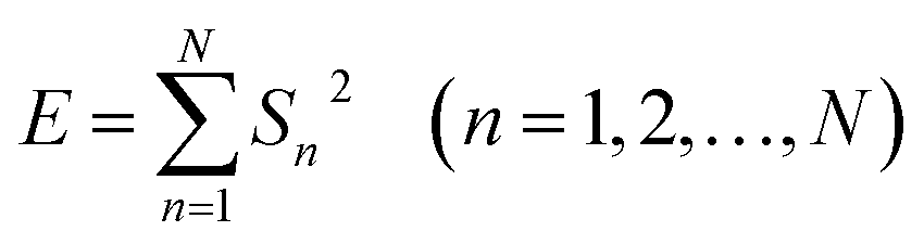 | (2) |
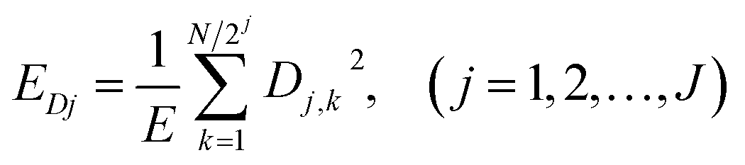 | (3) |
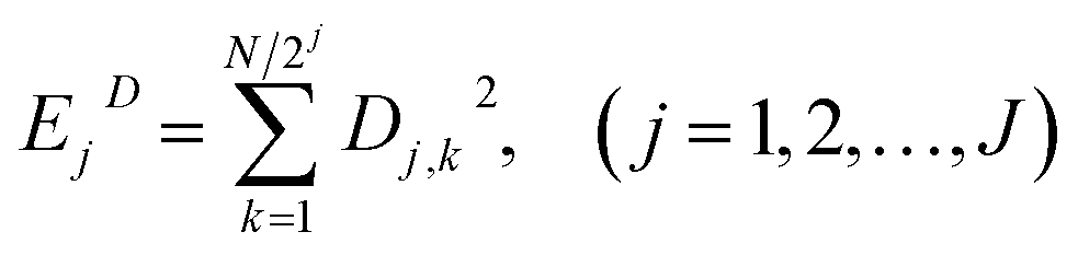 | (4) |
Experimental
Corrosive electrolytes (NaCl at different concentrations, 0.03 M, 0.06 M, 0.09 M and 0.12 M, and 0.06 M HCl) were prepared from analytical grade NaCl or HCl and double distilled water. The working electrode (pure copper) was mechanically cut and embedded into Teflon, leaving an exposed area of 0.5 cm2 as the working surface. Prior to each experiment, the working surface was successively abraded using sand paper from 400 to 1200 grit, polished to a mirror with 2.5 μm diamond paste, rinsed with distilled water in an ultrasonic cleaner for about 3 min (KQ5200B, Youyi Instrument Co., Ltd., China), degreased with acetone and finally dried under a cool N2 flow.EN was monitored as a function of time between the working electrode and the reference electrode (SCE) for the 1st hour, using the Powerlab/4sp (made in Australia) electrochemical interface through a GP amplifier controlled by Chart 5 software for the Windows XP operating system. This instrument is equipped with analog/hardware filters including an AA filter (anti-aliasing low-pass filters) to remove high frequency components before the signal is digitized, so that the acquisition of false data can be avoided.11 The EN records were collected at different sampling intervals (sampling frequency, f).
The weight loss of copper was measured according to the standard ISO 8407:2009, IDT. Copper coupons with dimensions of 100 mm × 80 mm × 0.2 mm were sectioned, and a water bath was used to maintain a specific temperature. SEM (SIRION, FEI Company, made in Holland) was utilized to examine the corrosion morphologies of the specimens.
Results and discussion
Influence of EN testing frequency
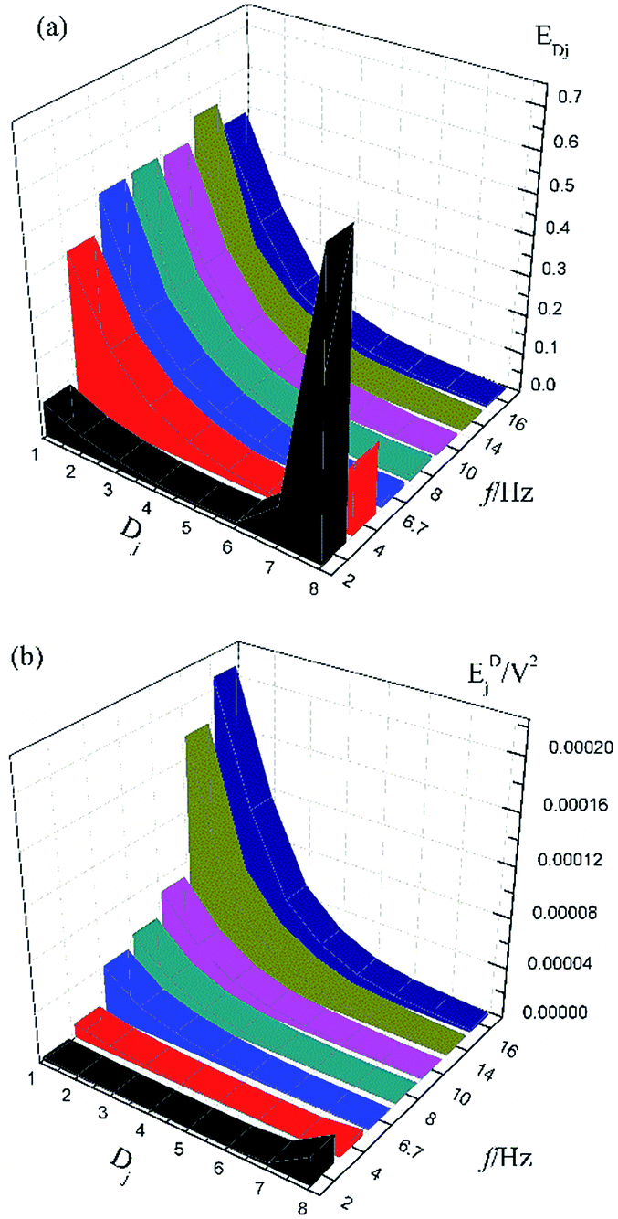
Fig. 1a shows the typical time-domain potential noise of the 1st hour for Cu corroding in 0.06 M NaCl neutral solutions at 20 °C, acquired at a commonly used data-sampling frequency (f) of 2 Hz. Fig. 1b and c show the RP-EDP plots of the noise generated during the same corrosion process at various concentrations of NaCl with different f (T = 20 °C). The difference is that the data shown in Fig. 1b were obtained after unitization (eqn (3)) whereas the data shown in Fig. 1c were obtained without unitization (eqn (4)). For 0.06 M, 0.09 M and 0.12 M NaCl (in Fig. 1b), the RP-EDPs remain the same and the maximum (relative) energy is in D1–D3 when f ≥ 8 Hz while it is in D7–D8 when f < 4 Hz. In 0.03 M NaCl, the maximum energy is in D1–D3 at each testing frequency.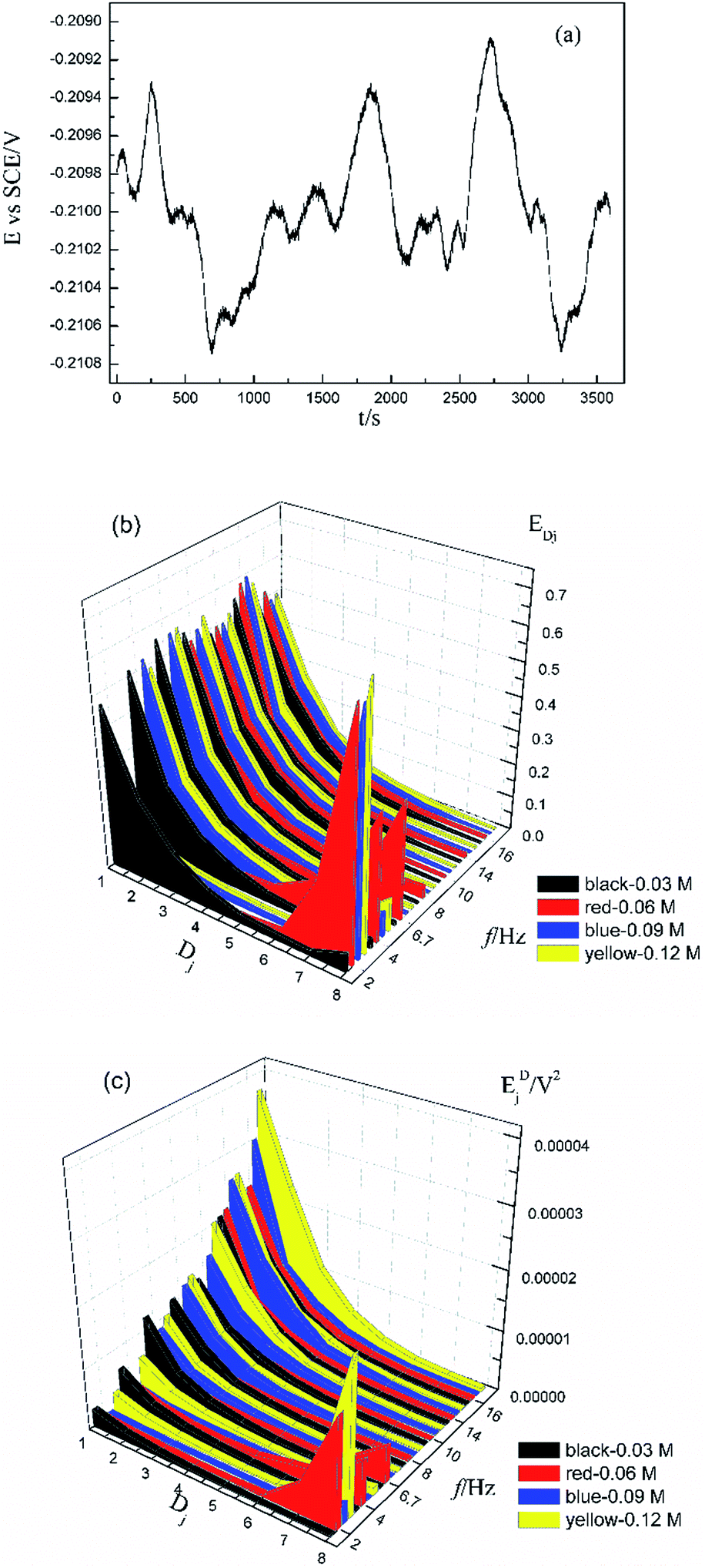 | ||
| Fig. 1 (a) Typical E–t curve at a frequency of 2 Hz, (b) EDj map (with unitization) and (c) EjD map with varied sampling frequencies and CNaCl: black–0.03 M, red–0.06 M, blue–0.09 M and yellow–0.12 M. | ||
Fig. 2 shows the RP-EDP plots with and without unitization for Cu corroding in 0.06 M HCl solutions. The maximum energy of RP-EDP is in D7–D8 when f < 4 Hz, while it is in D1–D3 when f ≥ 4 Hz. Considering Fig. 1 and 2, the characteristics of the RP-EDP plot are significantly influenced by sampling frequency. With increasing f, the maximum relative energy of the RP-EDP is in D1–D3 regardless of the corrosion ionic strengths.
 | ||
| Fig. 2 (a) EDj map (with unitization) and (b) EjD map at different sampling frequencies in 0.06 M HCl solution. | ||
Fig. 3 shows the PSD analysed using the MEM technique in different concentrations of NaCl and Fig. 4 shows the PSD in 0.06 M HCl. It is evident that PSD parameters (fc, W, and k) are also dependent on the adopted EN sampling frequency. In 0.06 M, 0.09 M and 0.12 M NaCl, these PSD parameters retain approximately equal values while f ≥ 8 Hz, whereas others (<8 Hz) are distinct from each other. Meanwhile the turning frequency point is 6.7 Hz in 0.03 M NaCl and 0.06 M HCl. These results are in accordance with the RP-EDP plots (Fig. 1 and 2), and also demonstrate the significant influence of the sampling frequency on the EN results.
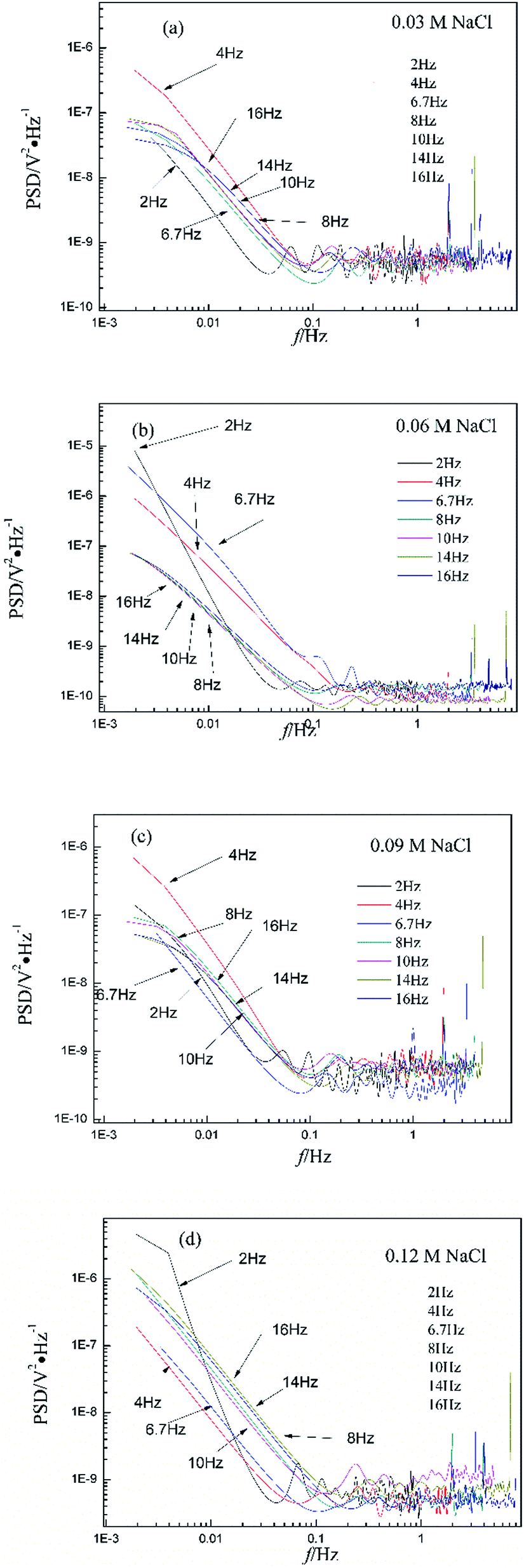 | ||
| Fig. 3 Influence of frequency effects on the PSD spectra in different concentrations of NaCl. | ||
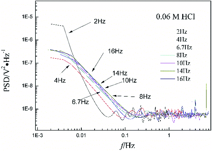 | ||
| Fig. 4 Influence of frequency effects on the PSD spectra in 0.06 M HCl. | ||
From a physicochemical viewpoint, the corrosion process should mainly depend on the natures of both the material (such as resistivity) and the environment (such as ambient temperature and erosive particles), but independent of the testing tools (such as the adopted EN sampling frequency). Additionally, the optimal or appropriate EN sampling frequency may be related to the investigated materials and their environment, and also possibly the research target of the researchers. Considering Fig. 1–4, the optimal testing frequency should be 6.7 Hz in 0.03 M NaCl and 0.06 M HCl and 8 Hz in 0.06 M, 0.09 M and 0.12 M NaCl. Previous reports14,15,29,30 claimed that an EN sampling frequency of 1–4 Hz (Δt = 0.25–1 s) seems to be adequate, a reason for which may be that their efforts focused on the noise resistance deduced from PSD spectra of potential and current noise.
Relationship between EN features and corrosion rate
Based on the above analyses and inspired by Searson and Dawson,15 the corroded morphologies (Fig. 5), the weight loss and the potential noise (Fig. 6a) of Cu corroding in 0.06 M NaCl neutral solutions at different temperatures were acquired, and the RP-EDPs without unitization were obtained (Fig. 6b). When performing EN tests, f = 8 Hz was adopted according to previous sections. Additionally, in order to ensure the comparability between the weight loss and the EN features, the same initial 1 h corroding period was selected as the timescale for both.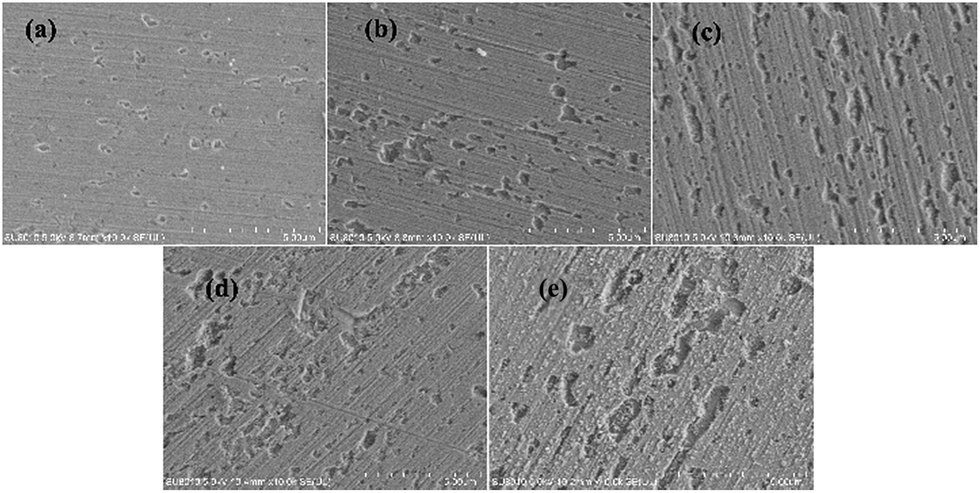 | ||
| Fig. 5 SEM images of the Cu morphologies after corroding for 1 h in 0.06 M NaCl solutions at different temperatures: (a) 20 °C, (b) 25 °C, (c) 30 °C, (d) 35 °C and (e) 40 °C. | ||
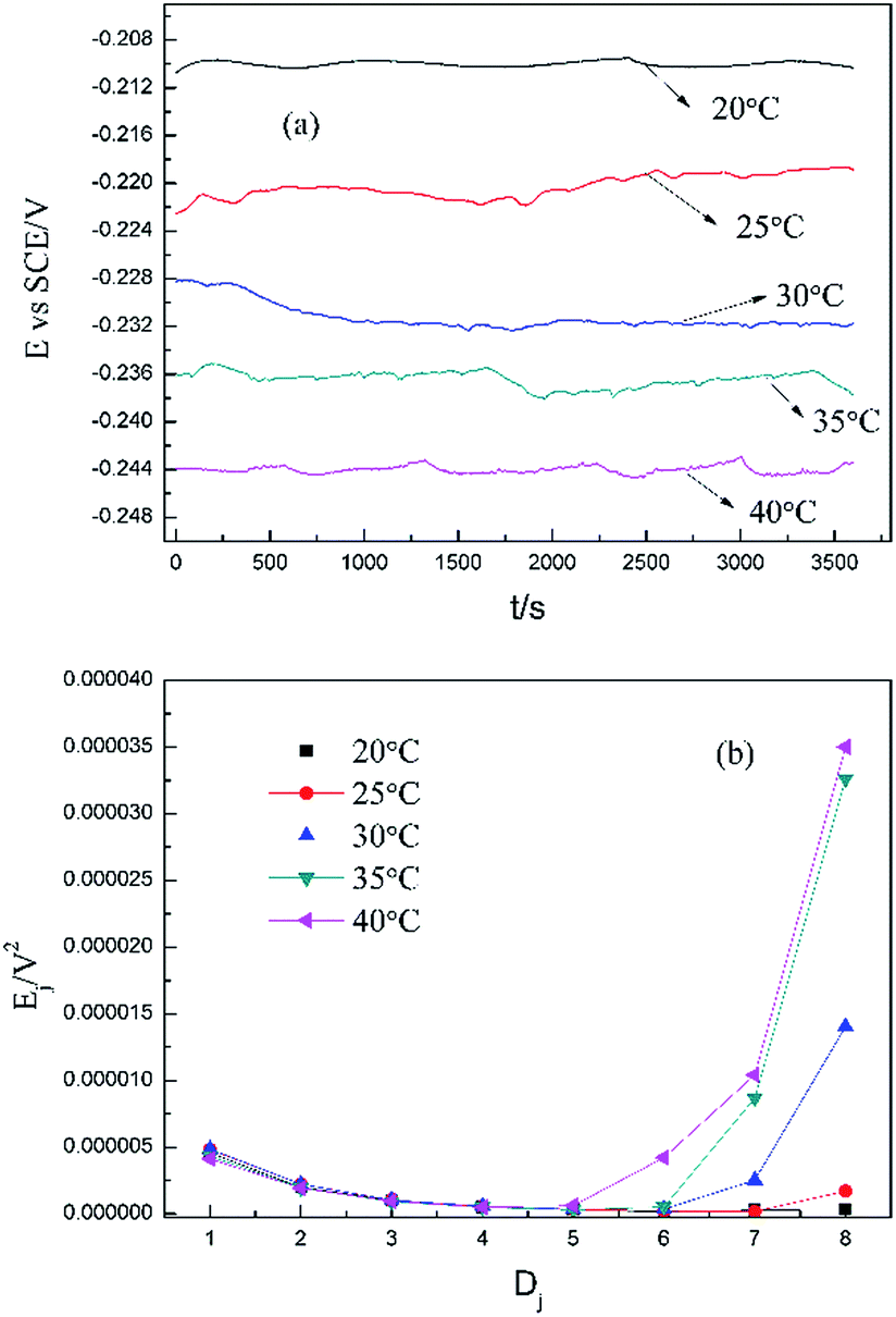 | ||
| Fig. 6 (a) Potential noise and (b) corresponding RP-EDP plots for copper corroding in 0.06 M NaCl at different temperatures (1st h, f = 8 Hz). | ||
Fig. 5 clearly shows the pitting corrosion type, and the diameter and depth of the pits increase with temperature, which intuitively represents an enhancement of the corrosion rate. Since the passivation time of a metastable pit is typically no longer than 20 s,31 and D8 mainly reflects the information of diffusion at f = 8 Hz,32 the sum of the energy (Fig. 6b) deposited in crystals D1 ∼ D7 (Ec), which represents the active pitting energy and therefore should reflect the severity of the corrosion of copper,8,33 is calculated and plotted versus the temperature (Fig. 7).
| Ec = E1D + E2D + E3D + E4D + E5D + E6D + E7D | (5) |
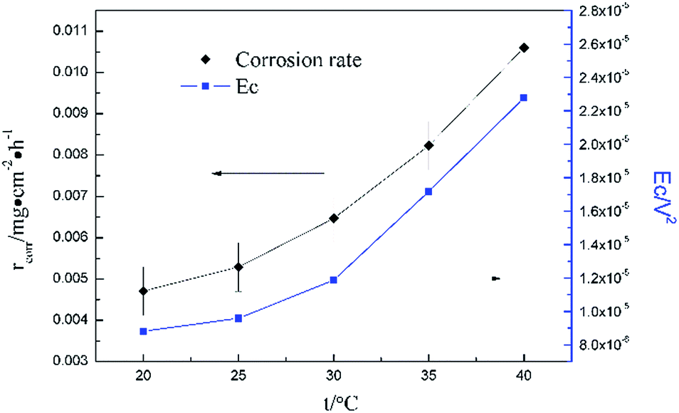 | ||
| Fig. 7 Dependence of corrosion energy Ec and rcorr on temperature in 0.06 M NaCl. | ||
rcorr (units mg cm−2 h−1) obtained from the weight loss is also repeatedly plotted in Fig. 7, and both rcorr and Ec increase with the elevation of the temperature. In other words, a good parallel relationship between the rcorr and Ec can be confirmed during the investigated timescale.
Conclusions
The electrochemical noise technique has been applied to describe the corrosion process of copper. The results show that the sampling frequency clearly changes both the EDP and the PSD spectra, before establishing the relation between the EDP and surface morphology, or the PSD spectra and corrosion kinetics, the optimal testing frequency should be taken into consideration strictly and logically.The corrosion energy, Ec, deduced from the FWT method, shows a similar variation trend with the corrosion rate. Hence, electrochemical noise offers a nondestructive on-line monitoring process, which can be easily carried out, and the proposed parameter Ec represents the corrosion rate or severity.
Conflicts of interest
There are no conflicts to declare.Acknowledgements
The authors wish to acknowledge financial support from the National Natural Science Foundation of China (Project 21273199 and 51131005).Notes and references
- D. H. Xia, S. Z. Song and Y. Behnamian, Corros. Eng., Sci. Technol., 2016, 51, 527–544 CrossRef.
- F. H. Cao, Z. Zhang, J. X. Su, Y. Y. Shi and J. Q. Zhang, Electrochim. Acta, 2006, 51, 1359–1364 CrossRef.
- T. Haruna, Y. Morikawa, S. Fujimoto and T. Shibata, Corros. Sci., 2003, 45, 2093–2104 CrossRef.
- D. Xia, S. Song, J. Wang, J. Shi, H. Bi and Z. Gao, Electrochem. Commun., 2012, 15, 88–92 CrossRef.
- A. Aballe, M. Bethencourt, F. J. Botana and M. Marcos, Electrochem. Commun., 1999, 1, 266–270 CrossRef.
- F. Zou and F. B. Cegla, Electrochem. Commun., 2017, 82, 134–138 CrossRef.
- C. Monticelli, G. Brunoro, A. Frignani and G. Trabanelli, J. Electrochem. Soc., 1992, 139, 706–711 CrossRef.
- Y. Chen, Z. N. Yang, Y. W. Liu, H. H. Zhang, J. Y. Yin, Y. Xie and Z. Zhang, J. Taiwan Inst. Chem. Eng., 2017, 80, 908–914 CrossRef.
- A. Aballe, M. Bethencourt, F. J. Botana and M. Marcos, Electrochim. Acta, 1999, 44, 4805–4816 CrossRef.
- A. M. Homborg, T. Tinga, X. Zhang, E. P. M. van Westing, P. J. Oonincx, G. M. Ferrari, J. H. W. de Wit and J. M. C. Mol, Electrochim. Acta, 2013, 104, 84–93 CrossRef.
- E. García-Ochoa and F. Corvo, Electrochem. Commun., 2010, 12, 826–830 CrossRef.
- F. Mansfeld, L. T. Han, C. C. Lee, C. Chen, G. Zhang and H. Xiao, Corros. Sci., 1997, 39, 255–279 CrossRef.
- F. Mansfeld and H. Xiao, J. Electrochem. Soc., 1993, 140, 2205–2209 CrossRef.
- T. Schauer, H. Greisiger and L. Dulog, Electrochim. Acta, 1998, 43, 2423–2433 CrossRef.
- P. C. Searson and J. L. Dawson, J. Electrochem. Soc., 1988, 135, 1908–1915 CrossRef.
- X. Huang, Y. Chen, T. Fu, Z. Zhang and J. Zhang, J. Electrochem. Soc., 2013, 160, D530–D537 CrossRef.
- L.-j. Zhang, X.-b. Zhu, Z. Zhang and J.-q. Zhang, Trans. Nonferrous Met. Soc. China, 2009, 19, 496–503 CrossRef.
- Z. Zhang, W. H. Leng, Q. Y. Cai, F. H. Cao and J. Q. Zhang, J. Electroanal. Chem., 2005, 578, 357–367 CrossRef.
- B. Zhao, J.-H. Li, R.-G. Hu, R.-G. Du and C.-J. Lin, Electrochim. Acta, 2007, 52, 3976–3984 CrossRef.
- X. Liu, T. Zhang, Y. Shao, G. Meng and F. Wang, Corros. Sci., 2010, 52, 892–900 CrossRef.
- Y. Chen, D. Qi, H. Wang, Z. Xu, C. Yi and Z. Zhang, Int. J. Electrochem. Sci., 2015, 10, 9056–9072 Search PubMed.
- W. Qafsaoui, M. W. Kendig, S. Joiret, H. Perrot and H. Takenouti, Corros. Sci., 2016, 106, 96–107 CrossRef.
- Z. Dong, X. Guo, J. Zheng and L. Xu, Electrochem. Commun., 2001, 3, 561–565 CrossRef.
- Z.-n. Yang, Z. Zhang, W.-h. Leng, K. Ling and J.-q. Zhang, Trans. Nonferrous Met. Soc. China, 2006, 16, 209–216 CrossRef.
- J. Smulko, K. Darowicki and A. Zieliński, Electrochem. Commun., 2002, 4, 388–391 CrossRef.
- C. Cai, Z. Zhang, F. Cao, Z. Gao, J. Zhang and C. Cao, J. Electroanal. Chem., 2005, 578, 143–150 CrossRef.
- S. M. Hoseinieh, A. M. Homborg, T. Shahrabi, J. M. C. Mol and B. Ramezanzadeh, Electrochim. Acta, 2016, 217, 226–241 CrossRef.
- M. C. Lefebvre and B. E. Conway, J. Electroanal. Chem., 2000, 480, 46–58 CrossRef.
- A. Nagiub and F. Mansfeld, Corros. Sci., 2001, 43, 2147–2171 CrossRef.
- A. M. Homborg, T. Tinga, X. Zhang, E. P. M. van Westing, P. J. Oonincx, J. H. W. de Wit and J. M. C. Mol, Electrochim. Acta, 2012, 70, 199–209 CrossRef.
- M. Shahidi, S. M. A. Hosseini and A. H. Jafari, Electrochim. Acta, 2011, 56, 9986–9997 CrossRef.
- Y. Y. Shi, Z. Zhang, F. H. Cao and J. Q. Zhang, Electrochim. Acta, 2008, 53, 2688–2698 CrossRef.
- C. Yi, X. Du, Y. Yang, Y. Chen, G. Wei, Z. Yang and Z. Zhang, Int. J. Electrochem. Sci., 2017, 12, 3597–3613 CrossRef.
| This journal is © The Royal Society of Chemistry 2018 |