 Open Access Article
Sustainable rose multiflora derived nitrogen/oxygen-enriched micro-/mesoporous carbon as a low-cost competitive electrode towards high-performance electrochemical supercapacitors†
Qiuli Chen‡
a,
Jinfeng Sun‡b,
Zhengluo Wanga,
Zhiwei Zhaoa,
Yanru Zhanga,
Yang Liub,
Linrui Hou*b and
Changzhou Yuan *b
*b
aSchool of Materials Science & Engineering, Anhui University of Technology, Ma'anshan, 243002, P. R. China
bSchool of Materials Science & Engineering, University of Jinan, Jinan, 250022, P. R. China. E-mail: mse_houlr@ujn.edu.cn; mse_yuancz@ujn.edu.cn; ayuancz@163.com; Fax: +86-531-82769410; Tel: +86-531-82769410
First published on 2nd March 2018
Abstract
Cost-efficient carbonaceous materials have been utilized extensively for advanced electrochemical supercapacitors. However, modest gravimetric/volumetric capacitances are the insuperable bottleneck in their practical applications. Herein, we develop a simple yet scalable method to fabricate low-cost micro-/mesoporous N/O-enriched carbon (NOC-K) by using natural rose multiflora as a precursor with KOH activation. The biomass-derived NOC-K is endowed with a large surface area of ∼1646.7 m2 g−1, micro-/mesoporosity with ∼61.3% microporosity, high surface wettability, and a high content of N (∼1.2 at%)/O (∼26.7 at%) species. When evaluated as an electroactive material for supercapacitors, the NOC-K electrode (5 mg cm−2) yields large gravimetric/volumetric specific capacitances of ∼340.0 F g−1 (∼238.0 F cm−3) at 0.5 A g−1, and even ∼200.0 F g−1 (∼140.0 F cm−3) at 5.0 A g−1, a low capacitance decay of ∼4.2% after 8200 consecutive cycles, and a striking specific energy of ∼8.3 W h kg−1 in aqueous KOH electrolyte, benefiting from its intrinsic structural and compositional superiorities. Moreover, a remarkable specific energy of ∼52.6 W h kg−1 and ∼96.6% capacitance retention over 6500 cycles for the NOC-K based symmetric cell are obtained with the organic electrolyte. More promisingly, the competitive NOC-K demonstrates enormous potential towards advanced supercapacitors both with aqueous and organic electrolytes as a sustainable electrode candidate.
1. Introduction
Electrochemical supercapacitors (ESs), especially electrochemical double-layer capacitors (EDLCs) with high power densities, high coulombic efficiencies (CEs), and long-term cycling lives, are considered to be one of the best potential high-power energy storage devices.1–4 As is well established, EDLCs generally store electrochemical energy based on the fast accumulation of charge in the double layer formed at the sur-/interfaces of the porous carbon electrodes with large specific surface area (SSA).1,3,4 Carbon materials, such as activated carbon,5 multi-modal porous carbon,6 hollow carbon spheres,7 modified activated carbon aerogel,8 carbon nanotubes9 and so on, have been comprehensively explored as the electrode materials for ESs. Unfortunately, the modest gravimetric/volumetric capacitances and low specific energy (SE) of the EDLCs still inherently hinder their practical widespread applications.2,3,10 Thus, numerous efforts have been made to design and explore various carbon materials with optimum pore structures and surface compositions/properties, with the aim to enhance their electrochemical behaviors particularly at high rates.In general, the superior specific capacitances (SCs) of carbon materials are mainly determined by their large SSA, hierarchical micro-/mesopores, and high-surface heteroatom content (such as O, N, B, P, etc.).3,4,10–18 To begin with, the high SSA can guarantee massive electroactive sites for fast and efficient charge accommodation.11–20 Besides, bi-modal micro-/mesopores greatly favor for convenient ion diffusion into the electrode bulk by providing ion highways, thus ensuring high-power property, and additionally contribute to large electroactive SSA meanwhile.3,18,20 In addition, heteroatom doping can partially form N- and O-based surface functional groups, which improves the surface wettability of carbon electrodes for effective charge storage.11,21–23 Notedly, the polar functional groups upon the carbon surface exhibit benign affinity to solvents with the same polarity, especially in the ubiquitous aqueous systems.24 Of particular note, the N doping also can change the intrinsic conductivity of carbon materials themselves by adjusting the giving/receiving capacity of the electrons in the C atom, which makes them even better electronic conductivity than their phase-pure counterparts, thanks to the high electronegativity, small atomic size, and additional free electrons of the N itself.3,13,20,21 Therefore, the nitrogen species have attracted the huge interest of many researchers around the word. It is noted that two strategies are generally explored to incorporate the elemental N into the porous carbon materials: post-treatment of porous carbon with extra N-based sources (such as, ammonia, urea, amoine, and so on) and in situ doping by directly pyrolyzing various N-containing precursors. Commonly, the former only introduces N-based functional groups on the surface of the carbon materials, while the latter can easily realize the homogeneous heteroatom doping into the bulk with controlled chemistry, rather than just on the surface of carbon electrodes.10
Recently, biomass materials, different from those artificial materials, have drawn enormous attentions, owing to their connate advantages including richness in nature, low cost, renewability and environmental friendlyness. Carbon materials derived from various biomasses not only possess unique special morphologies, but also can be in situ doped with the heteroatoms originally existing in these biomass precursors. Consequently, this type of carbon materials inherently owns higher market potential due to the lower cost than commercial carbon nanotubes and graphene.25 Nowadays, lots of pioneering works have been reported by using the human hair,14 dead leaves,16 shiitake,18 albumen,20 coconut shell,26 corn stover,27 banana peel,28 cashmere,6 and others as the precursors.
With aforementioned considerations in mind, herein, we proposed that a facile yet efficient synthesis of N/O co-functionalized carbons with bi-modal micro-/mesopores by using rose multiflora as the precursor. After KOH activation process at 800 °C, the as-resulted carbon electrode was obtained with high-content nitrogen (∼1.2 at%) and oxygen (∼26.7 at%) functionally doping, micro-/meso-porous channels with microporosity of ∼61.3%, large SSA (∼1646.7 m2 g−1) and appealing surface wettability. When evaluated as an electrode material for ESs, the KOH-activated nitrogen/oxygen-enriched carbon (denoted as NOC-K) electrode exhibited remarkable electrochemical capacitances both in aqueous KOH solution and organic tetraethylammonium tetrafluoroborate/propylene carbonate (TEABF4/PC) electrolyte, benefiting from its unique structural and compositional superiorities.
2. Experimental
2.1. Synthesis of the NOC-K
The waste rose multiflora (Anhui province, P. R. China) was thoroughly washed with de-ionized water and dried at 60 °C in an electric oven. The cleaned rose multiflora flower was first pyrolyzed in a tubular furnace at a temperature of 500 °C for 2 h with a heating rate of 5 °C min−1 in a high-purity N2 atmosphere. During following KOH-activated process, the as-obtained black powder was further mixed with the activation agent of KOH with a KOH/pre-pyrolyzed carbon ratio of 3![[thin space (1/6-em)]](https://www.rsc.org/images/entities/char_2009.gif) :
:![[thin space (1/6-em)]](https://www.rsc.org/images/entities/char_2009.gif) 1 (w/w). Afterwards, the mixture was activated under N2 flow at 800 °C for 2 h in a tubular furnace with a heating rate of 3 °C min−1. After the completion of the activation, the sample was allowed to cool to room temperature. After purified in diluent HCl solution, rinsed with de-ionized water until neutral, and dried at 60 °C, the resulting black NOC-K product was obtained. For comparison, the carbon prepared with the absence of KOH was designed as NOC, while other parameters were kept the same as those for the NOC-K.
1 (w/w). Afterwards, the mixture was activated under N2 flow at 800 °C for 2 h in a tubular furnace with a heating rate of 3 °C min−1. After the completion of the activation, the sample was allowed to cool to room temperature. After purified in diluent HCl solution, rinsed with de-ionized water until neutral, and dried at 60 °C, the resulting black NOC-K product was obtained. For comparison, the carbon prepared with the absence of KOH was designed as NOC, while other parameters were kept the same as those for the NOC-K.
2.2. Materials characterizations
Crystalline phases of the samples are examined by powder X-ray diffraction (XRD) (UltimaIV, Rigaku, Japan) using Cu Kα source over a 2θ range of 10–80°. Morphologies and structures of the resulting samples were examined by field-emission scanning electron microscopy (FESEM) (JEOL-6300F, 15 kV), transmission electron microscopy (TEM), and high-resolution TEM (HRTEM) (FEI, TECANI-20). N2 adsorption/desorption was determined by Brunauer–Emmett–Teller (BET) measurement by using an Autosorb-iQ surface area analyzer. X-ray photoelectron spectroscopy (XPS) was measured on a Thermo ESCALAB 250 Xi X-ray photoelectron spectrometer with Al kα excitation source (hν = 1486.6 eV). The Raman data was recorded by laser Raman (T6400, Jobionyzon Corp., France). The contact angle measurement was performed with Contact Angle System OCA.2.3. Electrochemical measurements
Cyclic voltammogram (CV) at different scanning rates, chronopotentiometry (CP) tests at various current densities and electrochemical impedance spectroscopy (EIS) were carried out on an IVIUM electrochemical workstation (The Netherlands). A three-electrode electrochemical configuration, where a Pt plate (1 cm2) and saturated calomel electrode (SCE) were used as the counter electrode and reference electrode, was applied for electrochemical evaluation of the as-obtained carbons in 6 M KOH solution at room temperature. The working electrodes were prepared by loading a slurry containing NOC-K or NOC, acetylene black and polytetrafluoroethylene in a weight ratio of 5![[thin space (1/6-em)]](https://www.rsc.org/images/entities/char_2009.gif) :
:![[thin space (1/6-em)]](https://www.rsc.org/images/entities/char_2009.gif) 2
2![[thin space (1/6-em)]](https://www.rsc.org/images/entities/char_2009.gif) :
:![[thin space (1/6-em)]](https://www.rsc.org/images/entities/char_2009.gif) 1. The mass loading of electroactive material on each electrode is 5 mg for three-electrode evaluation. And two-electrode symmetric cell with two identical electrodes were assembled into coin cells (CR2032) with 6 M KOH as the electrolyte.
1. The mass loading of electroactive material on each electrode is 5 mg for three-electrode evaluation. And two-electrode symmetric cell with two identical electrodes were assembled into coin cells (CR2032) with 6 M KOH as the electrolyte.
In addition, a symmetric cell was also electrochemically characterized in 1 M TEABF4/PC electrolyte. The electrode was prepared by mixing NOC-K or NOC, acetylene black, polyvinylidene difluoride (PVDF) binder (8![[thin space (1/6-em)]](https://www.rsc.org/images/entities/char_2009.gif) :
:![[thin space (1/6-em)]](https://www.rsc.org/images/entities/char_2009.gif) 1
1![[thin space (1/6-em)]](https://www.rsc.org/images/entities/char_2009.gif) :
:![[thin space (1/6-em)]](https://www.rsc.org/images/entities/char_2009.gif) 1, w/w/w) dispersed in the N-methylpyrrolidinone (NMP). The slurries coated on the Al and steel foils were employed as positive and negative electrodes. After dried in vacuum at 120 °C for 24 h, the electrodes were separated with glass fiber (GF/D, Whatman) in CR2032 coin-type cells for electrochemical measurement in 1 M TEABF4/PC electrolyte.
1, w/w/w) dispersed in the N-methylpyrrolidinone (NMP). The slurries coated on the Al and steel foils were employed as positive and negative electrodes. After dried in vacuum at 120 °C for 24 h, the electrodes were separated with glass fiber (GF/D, Whatman) in CR2032 coin-type cells for electrochemical measurement in 1 M TEABF4/PC electrolyte.
For the three-electrode systems or symmetric ESs, the mass capacitance (F g−1) and volumetric specific capacitance (VSC) (F cm−3) derived from galvanostatic tests can be calculated by the following equations:
 | (1) |
 | (2) |
For the symmetric cell, the SE and specific power (SP) were calculated as follows:
 | (3) |
 | (4) |
3. Results and discussion
3.1. Physicochemical characterizations
As schematically illustrated in Fig. 1, two procedures, involving pre-carbonization of the rose multiflora with a short flowering phase of just one month, and subsequent KOH-activation process, were carried out for the efficient and scalable fabrication of the NOC-K material. Compared with the common template synthesis strategies, the KOH-activation of the biomass, as a simple and effective method, is particularly suitable for practical industrial production. As identified by the XRD measurement (Fig. S1, ESI†), two broadened diffraction peaks appearing at 2θ = 24 and 43° are related to the (002) and (100) facets of the typical carbon material.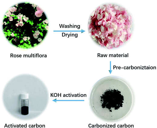 | ||
| Fig. 1 Schematic illustration of the fabricating procedure for the NOC-K with the rose multiflora as a starting material. | ||
Fig. 2a shows typical FESEM image of the hierarchical NOC-K product, and the sample presents loose morphology with interconnected hierarchical pores. TEM characterizations (Fig. 2b–d) were also carried out to further examine the specific microstructures of the sample more clearly. As shown in Fig. 2b, the discernable mesoporous structure can be presented for the NOC-K. Further high-magnification TEM (Fig. 2c) and HRTEM (Fig. 2d) observations show staggered and interpenetrated micropores dominating in the NOC-K sample along with several scattered mesopores, which would contribute to even more electroactive sites, and provide convenient and continuous channel meanwhile for the smooth entry and migration of electrolyte ions. As for the KOH activation, the expected products including CO2 and H2O formed in the activation process, and the removal of intercalated metallic K and K-based compounds by following washing both can result in the generation of well-developed pore network in the nano-scale and/or sub-nanometer range observed for the NOC-K specimen. Corresponding energy dispersive spectrometry (EDS) elementary mapping analysis of the NOC-K sample, as evidenced in Fig. 2e–h, visually confirms the homogeneous co-existence and uniform distribution of the C, N and O species in the whole NOC-K sample.
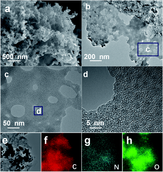 | ||
| Fig. 2 FESEM (a), TEM ((b) and (c)) and HRTEM (d) images of the NOC-K product, corresponding selected TEM area (e) for elemental ((f), C; (g), N and (h), O) mapping images. | ||
To better understand the unique bi-modal porous structure and SSA parameters, we measured N2 sorption isotherms of the NOC-K and NOC samples, as comparatively described in Fig. 3. Obviously, typical adsorption–desorption isotherms of the two, as plotted in Fig. 3a, are close to the combination form of the type I and IV according to the classic International Union of Pure and Applied Chemistry (IUPAC) definition. This distinct feature suggests the co-existence of the micro-/mesopores both in the NOC-K and NOC products, which can be well supported by their mesopore size distribution data (Fig. 3b) derived from the adsorption branches by the Barrett–Joyner–Halenda method, and the micropore size distribution (the inset in Fig. 3b) estimated by the Horvanth–Kawazone method. According to the calculation from the adsorption branch, the BET SSA of the NOC-K is ∼1646.7 m2 g−1, which is approximately two times that of the NOC (∼826.6 m2 g−1). And the total pore volume are estimated as ∼0.39 and ∼0.84 cm3 g−1 for the NOC and NOC-K, respectively, as determined from the N2 adsorption amount at P/P0 = 0.97. According to the ratio of micropore volume to total pore volume, ∼62.4% and ∼61.3% of the porosity for the NOC and NOC-K come from the micropores. As a result, the average pore sizes of the NOC and NOC-K can be derived as ∼2.1 and ∼2.3 nm, respectively. As noted, the NOC-K product obtains high SSA and well-developed porosity with even higher proportion mesoporosity, which are of vital significance to enhance the electrolyte accessibility to the microporous surface for efficient charge storage.
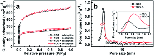 | ||
| Fig. 3 N2 adsorption–desorption isotherms (a), mesopore size distribution (b) and micropore size distribution (the inset in panel b) for the NOC and NOC-K samples. | ||
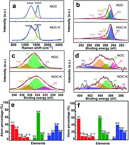
Fig. 4a demonstrates the Raman spectra of the NOC and NOC-K. Typically, both of the samples mainly show two distinct peaks located at around 1350 cm−1 (D-band) and 1590 cm−1 (G-band), respectively. As is known to all, the D-band corresponds to defect sites or disordered sp2-hybridized carbon atoms of graphite, and the G-band is related to the phonon mode in-plane vibration of sp2-bonded carbon atoms.29 The IG/ID values of the NOC and NOC-K are ∼0.85 and ∼0.65, respectively. The reduced IG/ID value of the NOC-K sample suggests more defective structure and lower graphitization owing to the subsequent high-temperature KOH activation.
Fig. 4b–f collectively summarize the high-resolution elemental XPS spectra of the NOC and NOC-K, and corresponding profiles fitted by using the Gaussian fitting method. Clearly, three elements including elemental carbon, oxygen and nitrogen are all discernable in the two products. Typically, the C 1s spectra for the two, as evidenced in Fig. 4b, can be deconvoluted into following five peaks including C![[double bond, length as m-dash]](https://www.rsc.org/images/entities/char_e001.gif) C (C-I, ∼284.6 eV), C–C (C-II, ∼285.0 eV), C–N/C–O (C-III, ∼285.6 eV), C
C (C-I, ∼284.6 eV), C–C (C-II, ∼285.0 eV), C–N/C–O (C-III, ∼285.6 eV), C![[double bond, length as m-dash]](https://www.rsc.org/images/entities/char_e001.gif) O (C-IV, ∼286.6), and O–C
O (C-IV, ∼286.6), and O–C![[double bond, length as m-dash]](https://www.rsc.org/images/entities/char_e001.gif) O (C-V, ∼288.4) bonds.30 Fig. 4c shows the deconvolutions of the O 1s spectra to identify the surface oxygen-containing functional groups upon the NOC and NOC-K products. Specifically, the three peaks at binding energies of ∼532.6, ∼533.8 and ∼535.1 eV correspond to the carbonyl (C
O (C-V, ∼288.4) bonds.30 Fig. 4c shows the deconvolutions of the O 1s spectra to identify the surface oxygen-containing functional groups upon the NOC and NOC-K products. Specifically, the three peaks at binding energies of ∼532.6, ∼533.8 and ∼535.1 eV correspond to the carbonyl (C![[double bond, length as m-dash]](https://www.rsc.org/images/entities/char_e001.gif) O) (O-I), hydroxyl (C–O) (O-II), and carbonxyl (O
O) (O-I), hydroxyl (C–O) (O-II), and carbonxyl (O![[double bond, length as m-dash]](https://www.rsc.org/images/entities/char_e001.gif) C–O) (O-III), respectively.31 The N 1s spectra of the samples (Fig. 4d) can be fitted well into four peaks centered at ∼397.8, ∼399.5, ∼400.6 and ∼402.7 eV, respectively, which are assigned to four types of nitrogen functional group, namely pyridinic (N-I), pyrrolic and/or pyridonic (N-II), quaternary nitrogen (N-III) and oxidized N-oxide species (N-IV).3,8,14,15 Compared with the NOC, total elemental nitrogen and carbon contents of the NOC-K sample are largely increased up to ∼1.2 at% and ∼72.1 at% from ∼0.5 at% and ∼66.2 at%, respectively, while the percentage of elemental oxygen is reduced from ∼33.3 at% to ∼26.7 at%. One especially note that the N-III and N-IV in the NOC-K (Fig. 4f), favoring for the rapid electronic transfer through the carbon electrodes,32,33 are estimated as ∼0.36 and ∼0.26 at%, higher than those for the NOC (N-III, ∼0.21 at%; N-IV, ∼0.12 at%) (Fig. 3e). There is no doubt that the unique feature of the NOC-K is greatly favorable for its enhanced electrochemical energy storage capacity, particularly at high rates, and to some extent, can make up for the lower graphitization of the NOC-K after KOH activation for enhanced rapid charge-storage ability.
C–O) (O-III), respectively.31 The N 1s spectra of the samples (Fig. 4d) can be fitted well into four peaks centered at ∼397.8, ∼399.5, ∼400.6 and ∼402.7 eV, respectively, which are assigned to four types of nitrogen functional group, namely pyridinic (N-I), pyrrolic and/or pyridonic (N-II), quaternary nitrogen (N-III) and oxidized N-oxide species (N-IV).3,8,14,15 Compared with the NOC, total elemental nitrogen and carbon contents of the NOC-K sample are largely increased up to ∼1.2 at% and ∼72.1 at% from ∼0.5 at% and ∼66.2 at%, respectively, while the percentage of elemental oxygen is reduced from ∼33.3 at% to ∼26.7 at%. One especially note that the N-III and N-IV in the NOC-K (Fig. 4f), favoring for the rapid electronic transfer through the carbon electrodes,32,33 are estimated as ∼0.36 and ∼0.26 at%, higher than those for the NOC (N-III, ∼0.21 at%; N-IV, ∼0.12 at%) (Fig. 3e). There is no doubt that the unique feature of the NOC-K is greatly favorable for its enhanced electrochemical energy storage capacity, particularly at high rates, and to some extent, can make up for the lower graphitization of the NOC-K after KOH activation for enhanced rapid charge-storage ability.
Besides, the surface N-/O-containing functional groups play a significant role in enhancing the hydrophilicity and wettability of the carbon electrodes. To further examine the wettability of the NOC and NOC-K electrodes, the contact angle measurement was conducted, as shown in Fig. 5. Visually, the contact angle of the NOC with the 6 M KOH aqueous solution is measured as ∼71.6°, which is greatly larger than that of the NOC-K (∼47°). It confirms the better wettability of the NOC-K sample with the aqueous KOH, which makes the electrolyte easily impregnate and reach the inner pore surface as large as possible for higher electrochemical efficiency of the total surface area towards enhanced electrochemical behaviors.
3.2. Electrochemical properties in aqueous KOH electrolyte
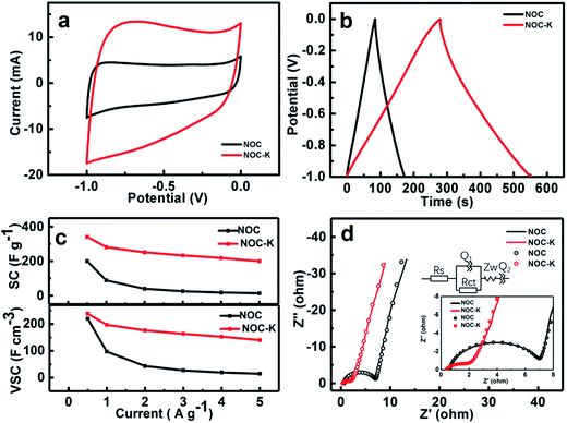
Due to large SSA and unique micro-/mesopores and surface wettability, along with the heteroatom doping in the NOC-K, the NOC-K sample can be highly expected to achieve outstanding electrochemical properties for advanced ESs as a high-performance electrode. Electrochemical performance of the NOC and NOC-K electrodes are first investigated detailedly in a three-electrode configure. Fig. 6a comparatively exhibits the typical CV curves of the NOC and NOC-K electrodes within the potential range from −1.0 to 0.0 V (vs. SCE) at a scan rate of 10 mV s−1 in 6 M KOH aqueous solution. The nearly rectangular CV shape observed here for the two evidences their typical electrochemical double-layer capacitance in nature. It is particularly worthy of mentioning that the electrochemical response current of the NOC-K is obviously increased when compared with that of the NOC electrode, which means that the NOC-K can deliver much higher energy-storage capacity. Fig. 6b displays the CP plots of the NOC and NOC-K at a current density of 1 A g−1 within the potential window ranged from −1.0 to 0.0 V (vs. SCE) in 6 M KOH electrolyte. Almost triangular appearance with linear charge–discharge plots suggests their good electrochemical supercapacitance. According to the data in Fig. 6b, the mass capacitance of the NOC-K with a loading of 5 mg cm−2 can be calculated as ∼281.6 F g−1, far higher than that for the NOC (∼88.6 F g−1) at the same current density of 1 A g−1 (i.e., 5 mA cm−2). Moreover, a capacitance as large as ∼340.0 F g−1 can be delivered by the NOC-K at 0.5 A g−1, while the NOC just delivers a capacitance of ∼199.8 F g−1, as derived from the CP plots (Fig. S2, ESI†). More impressively, when the current rates are further up to 2.0, 3.0, 4.0 and 5.0 A g−1, the SCs of the NPC-K in 6 M KOH still remain ∼251.6, ∼233.4, ∼218.4 and ∼200.0 F g−1, respectively, as demonstrated in Fig. 6c, that is, a SC retention of ∼58.8% can be obtained with the current increasing from 0.5 to 5 A g−1. More encouragingly, the SCs of our fabricated NOC-K are much higher than other biomass-based carbon electrodes even with less mass loadings (Table S1, ESI†). As a sharp contrast, the NOC only shows a SC of 13.6 F g−1 at the current density of 5 A g−1, corresponding to a SC degradation of 93.2% when the current is up to 5 from 0.5 A g−1. As analyzed above, the NOC-K displays superior rate behaviors especially for high-rate operation. Considering the high density of ∼1.1 g cm−3 for the NOC, a VSC of ∼219.8 F cm−3 can be obtained accordingly, as seen in Fig. 6c, which is somewhat less than that of the NOC-K (∼238.0 F cm−3) with a density of ∼0.7 g cm−3 at the same rate. Anyway, the VSCs for the NOC and NOC-K electrodes still can be compared with and/or higher than those of the porous carbon layer/graphene hybrids (∼212 F cm−3),34 carbon aerogels (∼123 F cm−3),35 apricot shell-based porous carbon (∼171 F cm−3),36 poly(vinylidene chloride)-derived porous carbon (∼214 F cm−3),37 and CO2-activated ordered mesoporous carbons (∼53 F cm−3),38 and so on. One should especially note that the NOC-K provides a VSC as high as ∼140.0 F cm−3, which is more than eight times higher than that of the NOC (∼15.0 F cm−3) at the same case of 5 A g−1, as shown in Fig. 6c.For further in-depth investigation into the specific electrochemical processes for the NOC and NOC-K electrodes, EIS tests were performed in the frequency from 0.01–105 Hz with an AC signal amplitude of 5 mV at a potential of −0.3 V (vs. SCE). Typical Nyquist plots and corresponding fitted files with the equivalent circuit model (the upper inset) for the two are collected in Fig. 6d, and the fitting parameters are summarized (Table S2, ESI†). The intersections of the plots at the X-axis reasonably represent the solution resistance (Rs), which to a certain extent is related to the intrinsic resistance of electroactive materials itself. As observed from the enlarged high-medium frequency region (the lower inset in Fig. 6d), the Rs of the NOC-K can be estimated as ∼0.4 ohm, somewhat smaller than that of the NOC (∼0.6 ohm). Furthermore, the semicircle, whose diameter stands for the charge transfer resistance (Rct), can be notable in Fig. 6d. The little semicircle of the NOC-K means its small Rct (∼1.6 ohm), and the Rct is approximated to ∼6.4 ohm for the NOC. Evidently, the smaller Rct and Rs values of the NOC-K electrode should well account for its superior power behaviors, as discussed in Fig. 6c, compared with those for the NOC electrode.
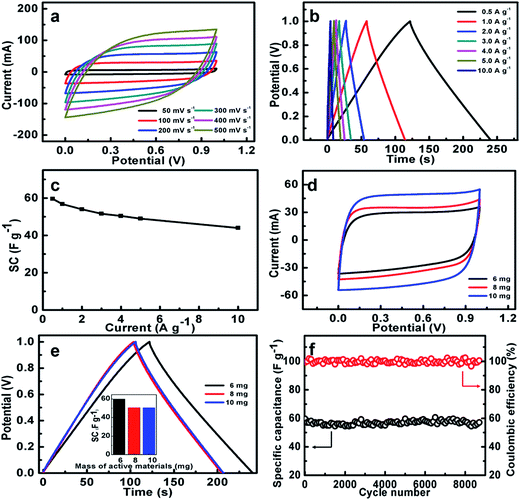
In order to investigate the practical application of the NOC-K as potential electrodes for ESs, a symmetric device was assembled by two identical NOC-K electrodes with total mass loading of 6 mg cm−2, along with the 6 M KOH as aqueous electrolyte. Fig. 7a shows the CV curves of the NOC-K based symmetric device with various sweep rates ranged from 50 to 500 mV s−1 in the potential window with a upper voltage of 1.0 V. Obviously, the symmetric device presents representative supercapacitive performance with quasi-rectangular shape voltammetry characteristics with respect to the zero-line and rapid current responses on voltage reversal at each end voltage, even at a high scanning rate of 500 mV s−1, suggesting its outstanding electrochemical properties in KOH. Fig. 7b plots the CP data of the symmetric supercapacitor at different current densities from 0.5 to 10.0 A g−1. It can be seen that all these charge–discharge curves show a standard regular triangle, further supporting its excellent double layer capacitance characteristics. According to the data in Fig. 7b, the SCs of the device can be quantified, and collected in Fig. 7c. Remarkably, the symmetric cell yields high SCs of ∼59.6, ∼56.8, ∼54.1, ∼51.6, ∼50.5, ∼49.1 and ∼44.1 F g−1, at the current densities of 0.5, 1.0, 2.0, 3.0, 4.0, 5.0 and 10.0 A g−1, respectively, that is, just a SC degradation of ∼74.0% is obtained with the current rate increasing from 0.5 to 10 A g−1, strongly suggesting its appealing rate behaviors. As is well known, electrochemical capacitances of any cell are hugely dependent upon the mass loadings of the electroactive material. Fig. 7d contrastively shows the CV curves at a sweep rate of 100 mV s−1 for the three symmetric capacitors with the total mass loadings of 6, 8 and 10 mg, respectively. Evidently, higher electrochemical current responses and larger integrated areas under the I–E curves are observed with the mass loading increasing. As calculated from the CP plots in Fig. 7e, the SCs of the symmetric cells are still maintained as ∼50.8 and ∼50.5 F g−1, which are ∼85.2% and ∼84.7% of the SC for the symmetric cell with the mass loading of 6 mg, when the total mass loading is up to 8 and 10 mg. The excellent SC independence of the NOC-K upon the mass loading fully highlights its remarkable capability for versatile potential applications.
Fig. 7f illustrates the long-span electrochemical stability of the symmetric device with a mass loading of 6 mg. Strikingly, the high SC retention of ∼95.8% over continuous 8200 cycles, i.e., ∼0.05% SC decay per 100 cycles, consistently verifies the excellent long-term cyclic stability of the NOC-K based symmetric cell at a current rate of 0.5 A g−1. Additionally, the CE of the cell is nearly always kept as high as ∼100%, suggesting its highly electrochemical reversibility for efficient charge storage. This fully confirms the promising advantages of the NOC-K electrode for advanced ESs.
3.3. Electrochemical properties in organic TEABF4/PC electrolyte
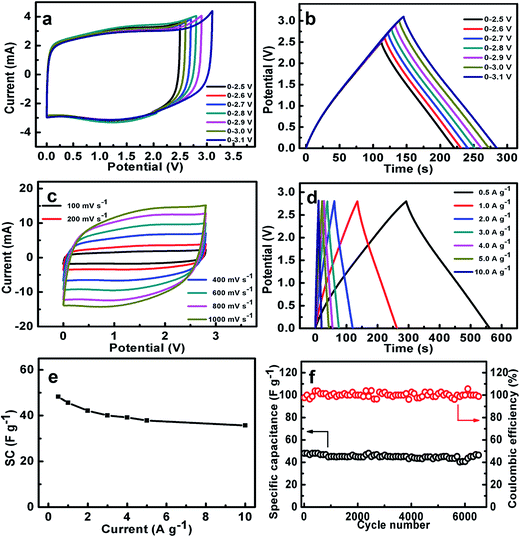
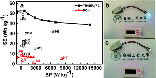
As we all know, the use of organic electrolytes is in high demand for practical application because of their even larger working potential window for high-performance ESs when compared to aqueous systems, which would further renders a large SE. We next test the coin-type symmetric supercapacitor with an organic TEABF4/PC as the electrolyte. Fig. 8a presents the CV curves of the symmetric device within the different upper potential limits from 2.5 to 3.1 V. Noteworthily, when the voltage is higher than 2.8 V, there exists a noticeable strong peak beyond 2.8 V, maybe corresponding to the electrolyte decomposition and/or some gas evolution. As a result, the CE of the symmetric device decreases from 99.7% (2.5 V) to 97.3% (3.1 V), as estimated from the CP plots in Fig. 8b. Furthermore, the SCs within the different voltage ranges just change from ∼44 to ∼45 F g−1. But serious SC degradation of ∼24.1% is observed after 6500 cycles within the potential window from 0.0 to 3.0 V (Fig. S4, ESI†). Therefore, we choose the upper voltage of 2.8 V for the following detailed characteristics. As seen in Fig. 8c, all these CV curves of the device exhibit nearly perfect rectangular shape at various rates from 100 to 1000 mV s−1 in the electrochemical window from 0.0 to 2.8 V, and still keep the geometrical rectangle even at a super-high rate of 1000 mV s−1, revealing the remarkable rate behaviors of the cell with the organic electrolyte. Typical CP plots at various current rates from 0.5 to 10 A g−1, as demonstrated in Fig. 8d, show symmetric triangle with nearly linear potential-time behaviors in the potential range from 0.0 to 2.8 V, further verifying the desirable electrochemical capacitances of the symmetric cell. Accordingly, the SCs of the symmetric supercapacitor, as plotted in Fig. 8e, can be calculated as ∼48.3, ∼45.6, ∼42.1, ∼40.1, ∼39.1, ∼37.9 and ∼35.7 F g−1 at the current densities of 0.5, 1.0, 2.0, 3.0, 4.0, 5.0 and 10.0 A g−1, respectively. Encouragingly, ∼73.4% of the capacitance still can be retained with the current rate increasing from 0.5 to 10.0 A g−1. This means the superior capacitive behaviors of the cell, which is of great importance in practical ESs, particularly under high-power operation conditions. Fig. 8f demonstrates the stable capacitance retention of NOC-K based symmetric supercapacitor over 6500 consecutive charge–discharge cycles with the upper voltage limit of 2.8 V at a current density of 0.5 A g−1. Remarkably, the device achieves a SC retention of ∼96.6% at the end of the 6500th cycle, which corresponds to a small SC degradation of ∼0.05% per 100 charge–discharge cycles over the prolonged cycles. Of note, it is much closed to the SC decay of ∼97.7% for the case with the upper voltage of 2.5 V (Fig. S5, ESI†). Besides this, the electrochemical CE is mainly kept around 100% during these consecutive cycles.Ragone plots of the NOC-K based symmetric devices with the TEABF4/PC and aqueous KOH electrolytes are further depicted in Fig. 9a. As shown in Fig. 9a, the aqueous symmetric cell with 6 M KOH as electrolyte just yields a maximal SE of ∼8.3 W h kg−1 (i.e., ∼2.7 W h L−1) along with a SP of 250 W kg−1, and at the case of 5 kW kg−1, only a SE of ∼6.1 W h kg−1, corresponding to a volumetric SE of ∼2.0 W h L−1, can be rendered. Appealingly, the gravimetric SE for the aqueous cell can be compared to, and/or even higher than others reported before,5,39,40,42,43,48 as plotted in Fig. 9a. As for the organic device, the highest SE of the cell with 1 M TEABF4/PC electrolyte has been obtained as large as ∼52.6 W h kg−1 (∼2.6 W h L−1) at a SP of ∼700 W kg−1. And attractively, the device still can achieve a SE of ∼38.9 W h kg−1 (∼1.9 W h L−1) at a higher SP of ∼14.0 kW kg−1, which is much larger than those for other carbon-based symmetric systems,5,41–49 as summarized in Fig. 9a. Moreover, the symmetric device with the TEABF4/PC electrolyte can efficiently power a light-emitting diode indicator, and maintain it for around 90 s, as visually demonstrated in Fig. 9b and c.
4. Conclusions
In summary, in the work, we adopted a simple yet industrializing synthetic strategy to fabricate low-cost N/O-enriched carbon (NOC-K) with bi-modal micro-/mesoporosity by using the natural rose multiflora as a precursor with the general KOH activation. Physicochemical characterizations demonstrated the rose multiflora-derived NOC-K possessed a large SSA, hierarchical micro-/mesoporosity, high surface wettability, and high-content elemental N and O. It was benefiting from these intrinsic structural and compositional advantages that the resultant NOC-K electrode with a mass loading of 5 mg cm−2 yielded large gravimetric/volumetric SCs of ∼340.0 F g−1 (∼238.0 F cm−3) at a current rate of 0.5 A g−1, and a SE of ∼8.3 W h kg−1 at 250 W kg−1, when evaluated as electroactive material in 6 M KOH aqueous solution for ESs. More competitively, the NOC-K based symmetric cell with 1 M TEABF4/PC organic electrolyte delivered an exciting SE of ∼52.6 W h kg−1 and excellent cycling performance with ∼0.05% SC decay per 100 cycles over 6500 charge–discharge cycles. Therefore, we strongly believe that the as-fabricated NOC-K holds enormous potential for advanced ESs, and even high-performance Na/Li-ion batteries as a promising electrode material.Conflicts of interest
The authors declare no conflict of interest.Acknowledgements
The authors acknowledge the financial support from National Natural Science Foundation of China (No. 51572005, 51772127).References
- P. Simon and Y. Gogotsi, Nat. Mater., 2008, 7, 845 CrossRef CAS PubMed.
- L. Z. Sheng, L. L. Jiang, T. Wei, Z. Liu and Z. J. Fan, Adv. Energy Mater., 2017, 19, 1700668 CrossRef.
- J. Zhao, Y. J. Li, G. L. Wang, T. Wei, Z. Liu, K. Cheng, K. Ye, K. Zhu, D. X. Cao and Z. J. Fan, J. Mater. Chem. A, 2017, 44, 23085 Search PubMed.
- B. E. Conway, Electrochemical Supercapacitors: Scientific Fundamentals and Technological Applications, Kluwer Academic/Plenum Publisher, New York, 1999 Search PubMed.
- L. Zhou, H. Cao, S. Q. Zhu, L. R. Hou and C. Z. Yuan, Green Chem., 2015, 17, 2373 RSC.
- B. Z. Fang, A. Bonakdarpour, M. S. Kim, J. H. Kim, D. P. Wilkinson and J. S. Yu, Microporous Mesoporous Mater., 2013, 182, 1 CrossRef CAS.
- B. Z. Fang, J. H. Kim, M. S. Kim, A. Bonakdarpour, A. Lam, D. P. Wilkinson and J. S. Yu, J. Mater. Chem., 2012, 22, 19031 RSC.
- Y. Z. Wei, B. Fang, S. Iwasa and M. Kumagai, J. Power Sources, 2005, 141, 386 CrossRef CAS.
- H. Jiang, T. Zhao, C. Z. Li and J. Ma, Chem. Commun., 2011, 47, 8590 RSC.
- L. R. Hou, L. Lian, D. K. Li, G. Pang, J. F. Li, X. G. Zhang, S. L. Xiong and C. Z. Yuan, Carbon, 2013, 64, 141 CrossRef CAS.
- D. Hulicova-Jurcakova, A. M. Puzly, O. I. Poddubnaya, F. Suarez-Garcia, J. M. D. Tascon and G. Q. Lu, J. Am. Chem. Soc., 2009, 131, 5026 CrossRef CAS PubMed.
- J. P. Paraknowitsch and A. Thomas, Energy Environ. Sci., 2013, 6, 2839 CAS.
- B. K. Guo, X. G. Sun, G. M. Veith, Z. H. Bi, S. M. Mahurin, L. Chen, C. Bridges, M. P. Paranthaman and D. Sheng, Adv. Energy Mater., 2013, 3, 708 CrossRef CAS.
- W. J. Qian, F. X. Sun, Y. H. Xu, L. H. Qiu, C. H. Liu, S. D. Wang and F. Yan, Energy Environ. Sci., 2014, 7, 379 CAS.
- B. Xu, S. S. Hou, G. P. Cao, F. Wu and Y. S. Yang, J. Mater. Chem., 2012, 22, 19088 RSC.
- M. Biswal, A. Banerjee, M. Deo and S. Oagle, Energy Environ. Sci., 2013, 6, 1249 CAS.
- W. T. Huang, H. Zhang, Y. Q. Huang, W. K. Wang and S. C. Wei, Carbon, 2011, 49, 838 CrossRef CAS.
- H. Cao, Z. Y. Chen, Q. L. Chen, C. Yang, L. R. Hou, M. Rehan, L. N. Tong and C. Z. Yuan, RSC Adv., 2016, 6, 81527 RSC.
- W. Y. Long, B. Z. Fang, A. Lgnaszak, Z. Z. Wu, Y. J. Wang and D. Wilkinson, Chem. Soc. Rev., 2017, 46, 7176 RSC.
- C. Z. Yuan, L. Zhou, S. Q. Zhu, H. Cao and L. R. Hou, J. Electrochem. Soc., 2015, 162, A781 CrossRef CAS.
- L. Zhao, L. Z. Fan, M. Q. Zhou, H. Guan, S. Qiao, M. Antonietti and M. M. Titirici, Adv. Mater., 2010, 22, 5202 CrossRef CAS PubMed.
- D. W. Wang, F. Li, L. C. Yin, X. Lu, Z. G. Chen, I. R. Gentle, G. Q. Lu and H. M. Cheng, Chem.–Eur. J., 2012, 18, 5345 CrossRef CAS PubMed.
- W. Ding, Z. D. Wei, S. G. Chen, X. Q. Qi, T. Yang, J. S. Hu, D. Wang, L. J. Wan, S. F. Alvi and L. Li, Angew. Chem., Int. Ed., 2013, 125, 11971 CrossRef.
- M. Yang and Z. Zhou, Adv. Sci., 2017, 4, 1600408 CrossRef PubMed.
- J. Hong, X. M. Wang, Z. R. Gu, J. D. Hoefelmeyer, K. Muthukumarappan and J. Julson, RSC Adv., 2014, 4, 14136 RSC.
- J. Mi, X. R. Wang, R. J. Fan, W. H. Qu and W. C. Li, Energy Fuels, 2012, 26, 5321 CrossRef CAS.
- H. Jin, X. M. Wang, Y. B. Shen and Z. R. Gu, J. Anal. Appl. Pyrolysis, 2014, 110, 18 CrossRef CAS.
- Y. K. Lv, L. H. Gan, M. X. Liu, W. Xiong, Z. J. Xu, D. Z. Zhu and D. S. Wright, J. Power Sources, 2012, 209, 152 CrossRef CAS.
- C. Chen, D. F. Yu, G. Y. Zhao, B. S. Du, W. Tang, L. Sun, Y. Sun, F. Besenbacher and M. Yu, Nano Energy, 2016, 27, 377 CrossRef CAS.
- P. Chao, X. B. Yan, R. T. Wang, J. W. Lang, Y. J. Ou and Q. J. Xue, Electrochim. Acta, 2013, 87, 401 CrossRef.
- D. Usachov, O. Vilkov, A. Gruneis, D. Haberer, A. Fedorov, V. K. Adamchuk, A. B. Preobrajenski, P. Dudin, A. Barinov, M. Oehzelt, C. Laubschat and D. V. VyalikhPreobrajenski, Nano Lett., 2011, 11, 5401 CrossRef CAS PubMed.
- Q. P. Luo, L. Huang, X. Gao, Y. L. Cheng, B. Yao, Z. M. Hu, J. Wan, X. Xu and J. Zhou, Naonotechnology, 2015, 26, 304004 CrossRef PubMed.
- H. Jiang, P. S. Lee and C. Z. Li, Energy Environ. Sci., 2013, 6, 41 CAS.
- J. Yan, Q. Wang, C. P Lin, W. Tong and Z. J. Fan, Adv. Energy Mater., 2014, 4, 1400500 CrossRef.
- Z. Zapata-Zulamita, F. Carrasco-Marin and C. Moreno-Castilla, J. Power Sources, 2012, 219, 80 CrossRef.
- B. Xu, Y. F. Chen, G. Wei, G. P. Cao, H. Zhang and Y. S. Yang, Mater. Chem. Phys., 2010, 124, 504 CrossRef CAS.
- B. Xu, F. Wu, S. Chen, Z. M. Zhou, G. P. Cao and Y. S. Yang, Electrochim. Acta, 2009, 54, 2185 CrossRef CAS.
- K. S. Xu, Q. M Gao, J. H. Jiang and J. Hu, Carbon, 2008, 46, 1718 CrossRef.
- Q. Long, W. M. Chen, H. H. Xu, X. Q. Xiong, J. Yan, Z. Feng, X. L. Hu, Y. Xin, Z. L. Zhang and Y. H. Huang, Energy Environ. Sci., 2013, 6, 2497 CAS.
- W. L. Zhang, M. Z. Zhao, R. Y. Liu, X. F. Wang and H. B. Lin, Colloids Surf., A, 2015, 484, 518 CrossRef CAS.
- Y. T. Luan, L. Wang., S. E. Guo, B. J. Jiang, D. D. Zhao, H. J. Yan, C. G. Tian and H. G. Fu, RSC Adv., 2015, 4, 42430 RSC.
- W. H. Qu, Y. Y. Xu, A. H. Lu, X. Q. Zhang and W. C. Li, Bioresour. Technol., 2005, 287, 428 Search PubMed.
- F. Sun, H. B. Wu, X. Liu, F. Liu, H. H. Zhou, J. H. Gao and Y. F. Lu, Nano Res., 2016, 9, 3209 CrossRef CAS.
- P. Cheng, S. Y. Gao, P. Y. Zang, X. F. Yang, Y. L. Bai, H. Xu, Z. H. Liu and Z. B. Lei, Carbon, 2015, 93, 315 CrossRef CAS.
- G. P. Hao, A. H. Lu, W. Dong, Z. Y. Jin, X. Q. Zhang, J. T. Zhang and W. C. Li, Adv. Energy Mater., 2013, 3, 1421 CrossRef CAS.
- S. M. Li, S. Y. Yang, Y. S. Wang, H. P. Tsai, H. W. Tien, S. T. Hsiao, W. H. Liao, C. L. Chang, C. C. M. Ma and C. C. Hu, J. Power Sources, 2015, 278, 218 CrossRef CAS.
- E. Frackowiak, G. Lota, J. Machnikowski, C. Vix-Guterl and F. Béguin, Electrochim. Acta, 2006, 51, 2209 CrossRef CAS.
- S. Q. Zhu, Q. L. Chen, Y. Y. Shi, Z. Y. Chen, R. Q. Bao, L. Zhou, L. R. Hou, K. N. Hui and C. Z. Chang, J. Solid State Electrochem., 2016, 20, 713 CrossRef CAS.
- L. P. Kong, C. F. Zhang, J. T. Wang, W. M. Qiao, L. C. Ling and D. H. Long, ACS Nano, 2015, 9, 11200 CrossRef CAS PubMed.
Footnotes |
| † Electronic supplementary information (ESI) available: Electronic supporting information corresponding XRD pattern, charge–discharge plots, electrochemical comparisons with other carbon-based electrodes, EIS simulated results, and cycling performance of the symmetric devices within the potential range from 0.0 to 2.5 or 3.0 V. See DOI: 10.1039/c8ra00858b |
| ‡ These authors contributed equally to this work. |
| This journal is © The Royal Society of Chemistry 2018 |

