 Open Access Article
Creative Commons Attribution 3.0 Unported Licence
Electrocatalytic oxidation of ethanol at Pd, Pt, Pd/Pt and Pt/Pd nano particles supported on poly 1,8-diaminonaphthalene film in alkaline medium
K. M. Hassan *a,
A. A. Hathootb,
R. Maherb and
M. Abdel Azzemb
aElectrochemistry Research Laboratory, Physics and Mathematics Engineering Department, Faculty of Electronic Engineering, Menoufia University, Egypt. E-mail: drkhalidhassan73@gmail.com; Tel: +201001303945
bElectrochemistry Laboratory, Chemistry Department, Faculty of Science, Menoufia University, Egypt
First published on 24th April 2018
Abstract
An ethanol oxidation reaction (EOR) in alkaline medium was carried out at palladium (Pd) or platinum (Pt) nanoparticles/poly 1,8-diaminonaphthalene (p1,8-DAN) composite catalyst electrodes. Pd and Pt were incorporated onto a p1,8-DAN/GC electrode by a cyclic voltammetry (CV) strategy. The obtained Pd/p1,8-DAN/GC, Pt/p1,8-DAN/GC, Pt/Pd/p1,8-DAN/GC and Pd/Pt/p1,8-DAN/GC modified electrodes were characterized by scanning electron microscopy (SEM), energy dispersive X-ray spectroscopy (EDX) and cyclic voltammetry (CV) techniques. Electrode surface areas (ESAs) of the obtained catalysts were calculated by carbon monoxide (CO) adsorption using differential electrochemical mass spectroscopy (DEMS). The electrocatalytic oxidation of ethanol (EtOH) at the catalyst electrodes was considered in 0.5 M NaOH solutions by CV and chronoamperometric techniques. The catalyst electrodes significantly enhanced the catalytic efficiency for EOR compared to a bare glassy carbon (GC) electrode. Bimetallic catalyst electrodes demonstrate improved catalytic activity, superior durability and higher tolerance to (CO) poison generated in the development of EOR compared with Pd/p1,8-DAN and Pt/p1,8-DAN catalysts, giving priority to Pt/Pd/p1,8-DAN/GC electrodes. Viability parameters, such as NaOH and EtOH concentrations, scan rate and upper potential limits, were examined and analyzed. This study suggests that the prepared catalysts have pronounced potential applications in direct EOR in fuel cells.
1. Introduction
In recent decades, direct oxidation fuel cells have pulled in extraordinary consideration since they offer a productive and green innovation for energy conversion. Nevertheless, the utilization of hydrogen is restricted by issues of fabrication, purification, storage and distribution. Alkaline direct oxidation fuel cells engaging on several liquid fuels promise to be an environmentally friendly energy technology, mainly because of the enhanced performance as a result of fast electrochemical kinetics on both the anode and cathode.1–7 Among several liquid fuels, ethanol (EtOH) has been documented to be the most appropriate fuel as it is a sustainable and carbon-neutral transport fuel.8 Insignificant poisoning effects in alkaline solutions were also detected.6 In electrochemical oxidation, the electrode material is a fundamental factor, and a highly effective electrocatalyst is required. Conducting polymer matrixes with excellent stability, a porous nature and high active surface area (like poly 1,8-diaminonaphthalene) are attractive and favorable supports for incorporation of the catalyst nanoparticles (NPs).9–11 The high available surface area, the synergistic impact between NPs and the conducting polymer and the improved tolerance against poisoning by adsorbed carbon monoxide (COads), which is formed during the EtOH electrooxidation, enhance the effectiveness of the electrocatalyst and reduce the surface poisoning. The supported structure prevents agglomeration and affords a high degree of distribution of MNPs during the electrodeposition for liquid fuel oxidation. It could be considered as a redox mediator between the electrode and the electroactive reactant by electron–proton exchange. Composites of conducting polymers with NPs offer a rapid electron transfer pathway through the polymer layer during the electrochemical process. Therefore, metal electrodeposition on the conducting polymers can provide a low-cost and appropriate approach for electrode modification.12–14 Pt has been broadly used as the anode catalyst for liquid fuel oxidation due to its excellent electrocatalytic capability.15–17Disregarding the critical changes made up to now in the performance of direct oxidation fuel cells, various technical obstacles to their marketable application have continued, including the low performance of the anodes for the oxidation process and the high cost of noble metal platinum-based (Pt-based) catalysts.18–20 Diverse methodologies have been utilized to help the commercial application of direct oxidation fuel cells: for example, the incorporation of another metal into Pt, controlling the catalyst morphology, and choosing appropriate support materials.11,21,22
The incorporation of a second metallic element into Pt has been recognized to help the development of liquid fuel oxidation kinetics considerably.9,11,12,23 Referring to the dual-function and fundamental mechanism, a second metal can provide oxygen containing species at lower potentials and reduce the bond strength of Pt–COads, and then support the oxidation removal of CO to CO2.21 Palladium (Pd) has been used as an alternative material to Pt, mainly in fuel cells, due to its reasonably abundant source and proper electrocatalytic activity.6,21,24 There are few reports on utilizing conducting polymers as dispersion media for Pt and Pd NPs. In this paper, we report a simple strategy for the preparation of a poly 1,8-diaminonaphthalene/glassy carbon modified electrode as an effective support to anchor single and bimetallic Pd and Pt NPs.25 This material offers a high potential for an electrocatalyst support for an EtOH oxidation reaction (EOR).
2. Experimental
2.1. Materials
1,8-DAN of analytical grade obtained from Aldrich was conserved in the dark and stored in a refrigerator before use. Sulfuric acid (H2SO4 98%) (Merck), acetonitrile (ACN) (99.9%), HPLC (LAB-SCAN) and EtOH (ADWIC) (98%) were used without additional purification. Sodium hydroxide (NaOH), palladium chloride (PdCl2) and chloroplatinic acid hexahydrate (H2PtCl6·6H2O) were analytical grade chemicals. Diamond paste (Presi) 2.0 μm and freshly distilled water were used continuously.2.2. Instruments
SEM images were recorded using QUANTA FEG 250 equipped with an energy dispersive ray spectrometer (EDS). Electrochemical measurements were recorded using a potentiostat Model BASi EPSILON. All electrochemical experiments were achieved using an electrochemical cell, with a conventional three-electrode system. A GC electrode (3.0 mm diameter) was used as the working electrode and Pt wire as an auxiliary one. All reported potentials were recorded with respect to an Ag/AgCl reference electrode. Electrochemical surface area (ESA) measurements were carried out using an EG&G potentiostat (model 273A) in combination with LabVIEW software (National Instruments GmbH, Munich, Germany) for recording cyclic voltammograms. Carbon dioxide (CO2) was detected by differential electrochemical mass spectroscopy (DEMS) using a quadrupole mass spectrometer (Balzer QMG-422) with dual thin layer flow through a cell in which a hydrophobic Teflon membrane forms the interface between the electrolyte and the vacuum.2.3. Experimental procedures
3. Results and discussion
3.1. Electrochemical performances and surface morphology of the catalysts
Cyclic voltammograms (CVs) of both Pd/p1,8-DAN/GC and Pt/p1,8-DAN/GC catalyst electrodes in 0.5 M NaOH in the potential range of −0.9 V to 0.3 V were recorded at scan rate of 0.05 V s−1, as shown in Fig. 1. In the forward scan, oxidation of Pd or Pt forming an oxide layer was observed in a potential range from 0.0 V to 0.3 V. In the backward sweep, the oxide stripping peaks for Pd/p1,8-DAN/GC and Pt/p1,8-DAN/GC electrodes were revealed at −0.53 V and −0.15 V, respectively.24,27,28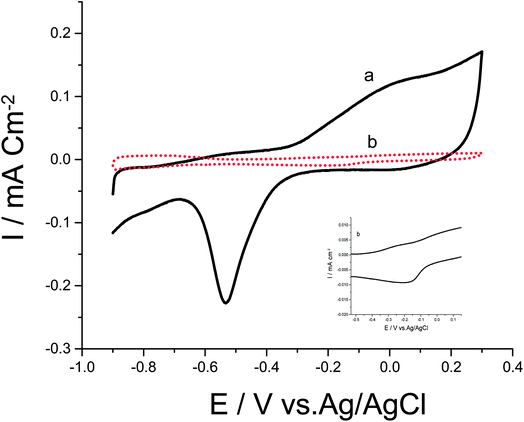 | ||
| Fig. 1 CVs of (a) Pd/p1,8-DAN/GC and (b) Pt/p1,8-DAN/GC modified electrodes in 0.5 M NaOH at a scan rate of 0.05 V s−1. | ||
To date, a lot of bimetallic materials with synergistically improved activities have been considered based on Pt in combination with its neighboring transition metals. Among these materials, a Pt/Pd catalyst is more stable than other bimetallic catalysts at high potentials.29,30 The electrochemical behaviors of bimetallic Pd/Pt/p1,8-DAN/GC and Pt/Pd/p1,8-DAN/GC catalysts were investigated in 0.5 M NaOH in the potential range of −0.9 V to 0.3 V at a scan rate of 0.05 V s−1, as exhibited in Fig. 2. Both catalysts demonstrated characteristic anodic peaks for metal oxide formation in the forward sweep, whereas the cathodic peaks at −0.35 V and −0.5 V were due to the oxide stripping of the Pd/Pt/p1,8-DAN/GC and Pt/Pd/p1,8-DAN/GC electrodes, respectively.
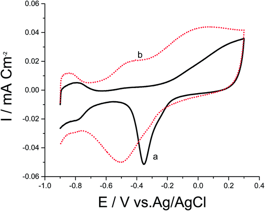 | ||
| Fig. 2 CVs of (a) Pd/Pt/p1,8-DAN/GC and (b) Pt/Pd/p1,8-DAN/GC modified electrodes in 0.5 M NaOH at a scan rate of 0.05 V s−1. | ||
ESAs of the prepared catalysts were computed by recording faradic and ionic currents for the oxidation of COads to CO2 by CV and DEMS procedures (figure not shown). Anodic oxidation peaks appearing at 0.9 V for Pd/p1,8-DAN/GC, and at 0.7 V for the other three catalysts were ascribed to the combined impact of oxidation of COads and the partial surface oxidation of Pt or Pd to metal oxide (PtO or PdO). Cathodic reduction peaks shown in the reverse scan were credited to metal oxide reductions. Charges associated with the metal oxide reductions were subtracted from the anodic charges and the charge corresponding to COads oxidation.31–33 The ionic signal for m/z = 44 in 0.5 M H2SO4 at a scan rate of 0.01 V s−1 at a flow rate of 5 μL s−1 was utilized for ESA calculations according to the following equation:
 | (1) |
The acquired ESAs of the catalyst electrodes were 0.2, 2.03, 1.51 and 1.88 cm2 for Pd/p1,8-DAN/GC, Pt/p1,8-DAN/GC, Pd/Pt/p1,8-DAN/GC and Pt/Pd/p1,8-DAN/GC modified electrodes, respectively. The results revealed that the Pt/p1,8-DAN/GC modified electrode has the largest ESA while Pd/p1,8-DAN/GC has the lowest. The ESA of the Pd/p1,8-DAN/GC modified electrode was enhanced by the presence of the second metal layer detected in the Pt/Pd/p1,8-DAN/GC modified electrode. These outcomes showed the significant role of the order of electro-deposition of the MNPs. The higher electroactive surface area makes the modified electrode a suitable catalyst.
To compare the activities of different catalysts in terms of profitable efficiency, the current is generally normalized by the mass of loaded metal. Despite the fact that the mass-current density characterizes the economic efficiency of a catalyst, this does not consider the surface area of active metal sites. Electrochemical active surface area (ECSA) is an essential parameter that explains the number of electrochemical active sites with reference to the mass of noble metal34,35 as follows:
| ECSA = Q/sl | (2) |
| ECSA (m2 gm−1) | Metal loading (gm m−2) | Catalyst |
|---|---|---|
| 7.2 | 17.13 | Pd/p1,8-DAN/GC |
| 9.21 | 7.21 | Pt/p1,8-DAN/GC |
| 25.69 | 4.97 | Pd/Pt/p1,8-DAN/GC |
| 157.58 | 3.447 | Pt/Pd/p1,8-DAN/GC |
The surface topographies of the obtained catalysts were evaluated using SEM, as shown in Fig. 3A–D, which displays significant differences in the surface structures of the four catalysts.
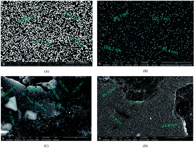 | ||
| Fig. 3 SEM micrographs of freshly prepared catalyst electrodes: (A) Pd/p1,8-DAN/GC, (B) Pt/p1,8-DAN/GC, (C) Pt/Pd/p1,8-DAN/GC and (D) Pd/Pt/p1,8-DAN/GC. | ||
Electrodeposited Pd (shiny particles) and Pt (light-grey) particle sizes are in the range of 88.4–96.3 nm and 89.3 nm to 168.2 nm, respectively, as shown in Fig. 3A and B. Fig. 3C displays good distributions of Pd and Pt particles, where Pd is in the core and Pt is outside over the whole surface of the p1,8-DAN/GC modified electrode in a size range of 61.7–96.35 nm. When the order of deposition is changed, the aggregated particles are formed in almost the same range, as shown in Fig. 3D.
Furthermore, EDX analysis was conducted (figure not shown) where both Pt and Pd NPs in the monometallic catalysts were dispersed in the p1,8-DAN film with percentages of 5.01% and 0.9%, respectively. Moreover, in the bimetallic layer, EDX results revealed the presence of both dispersed MNPs in the order of 0.07, 0.42% and 0.36, 0.37%, for Pd/Pt/p1,8-DAN/GC and Pt/Pd/p1,8-DAN/GC catalyst electrodes, respectively.
3.2. Electrocatalytic activities of the catalysts toward EOR
Electrocatalytic performances of a bare GC electrode, p1,8-DAN, Pd/p1,8-DAN, Pt/p1,8-DAN, Pd/Pt/p1,8-DAN and Pt/Pd/p1,8-DAN catalyst electrodes toward EOR were assessed by the CV procedure in 0.5 M NaOH containing 0.7 M EtOH at a sweep rate of 0.05 V s−1. Typical CV profiles indicated that the GC electrode and p1,8-DAN modified electrode had no electrocatalytic activities. On the other hand, at Pd/p1,8-DAN/GC, Pt/p1,8-DAN/GC, Pd/Pt/p1,8-DAN/GC and Pt/Pd/p1,8-DAN/GC catalyst electrodes, two well-characterized oxidation peaks in the forward and reverse scans (Epf and Epb, respectively)6 appeared at −0.20 V and −0.44 V, −0.20 V and −0.35 V, −0.12 V and −0.24 V, and −0.06 V and −0.22 V, respectively (Fig. 4A–D). These oxidation peaks could be ascribed to EtOH electrooxidation.8,19,36–38 It is important to mention that the reduction peak (Epr) of Pd oxide at Pd/p1,8-DAN was observed at a lower potential (Epr = −0.35 V)8 than that at Pd/Pt/p1,8-DAN (Epr = −0.075 V), indicating that single PdNPs oxide is more easily reduced than binary MNPs oxide.19 Several significant differences were observed: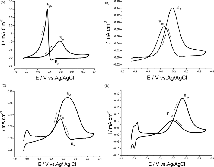 | ||
| Fig. 4 CVs of 0.7 M EtOH in 0.5 M NaOH at (A) Pd/p1,8-DAN/GC, (B) Pt/p1,8-DAN/GC, (C) Pd/Pt/p1,8-DAN/GC and (D) Pt/Pd/p1,8-DAN/GC catalyst electrodes at a scan rate of 0.05 V s−1. | ||
(1) Hydrogen adsorption/desorption regions were significantly depressed at Pd/p1,8-DAN and Pt/p1,8-DAN because of surface blocking. This behavior was detected at Pd/Pt/p1,8-DAN and Pt/Pd/p1,8-DAN catalysts in the region between −0.85 and −0.7 V. This could be attributed to the presence of free NPs at bimetallic catalyst surfaces.19,39–43
(2) The current density and ECSA were different due to the surface area and the charge of the catalyst electrodes.
(3) Epf and Epb varied with the metal type of the supported catalyst, giving lower values at Pt/Pd/p1,8-DAN to reach −0.06 and −0.22 V, respectively, as presented in Table 2.
| Catalyst | Current densitya (J/mA cm−2) | Current densityb (j/mA gm−1) | Eonset (V) vs. Ag/AgCl | Epf (V) vs. Ag/AgCl | Epb (V) vs. Ag/AgCl | Tolerance | ||
|---|---|---|---|---|---|---|---|---|
| Jpf | Jpb | jpf | jpb | |||||
| a From DEMS calculation.b From mass active calculation. | ||||||||
| Pd/p1,8-DAN/GC | 1.02 | 2.93 | 0.028 | 0.08 | −0.53 | −0.20 | −0.44 | 0.35 |
| Pt/p1,8-DAN/GC | 0.14 | 0.08 | 0.03 | 0.0171 | −0.53 | −0.20 | −0.35 | 1.75 |
| Pd/Pt/p1,8-DAN/GC | 0.17 | 0.08 | 0.01 | 0.0047 | −0.45 | −0.22 | −0.24 | 2.13 |
| Pt/Pd/p1,8-DAN/GC | 0.26 | 0.1 | 0.003 | 0.00115 | −0.39 | −0.06 | −0.22 | 2.6 |
(4) In the EOR mechanism at Pt and Pd catalysts it is considered that the onset potential (Eonset) is related to the breaking of C–H bonds and the consequent removal of intermediates such as COad by oxidation with adsorbed OH− (OHad−) provided by Pd–OH and/or Pt–OH sites.27,44 Also, Eonset for EOR is an essential factor for determining the electroactivity of the catalyst. At Pd/p1,8-DAN and Pt/p1,8-DAN, Eonset had similar values of around −0.53 V while it moved in a positive direction for both Pd/Pt/p1,8-DAN and Pt/Pd/p1,8-DAN, to reach −0.45 V and −0.39 V, respectively.
(5) The ratio of the current density value of the forward oxidation peak to that of the backward oxidation peak was utilized to determine the tolerance of the prepared catalysts to accumulated carbonaceous intermediates generated during EOR on the electrode surface.34 A higher tolerance ratio demonstrates greater efficiency of EOR during the forward scan and less accumulation of carbonaceous residues on the electrode surface.27 Tolerance ratios for the four studied catalysts were computed and are collected in Table 2. It was discovered that the tolerance order was Pt/Pd/p1,8-DAN > Pd/Pt/p1,8-DAN > Pt/p1,8-DAN > Pd/p1,8-DAN. The improved catalytic activity of bimetallic over pure metals is generally ascribed to several effects. It is considered that the alloying component tends to leach out under electrochemical conditions and results in a surface rich in noble metal.45 Consequently, it produces an additional active surface compared to monometallic alone. The alloy has also changed the geometric ligand (e.g. diminishes the Pt–Pt bond distance) or electronic impact (e.g. increase in Pt d-electron vacancies), so one of the components modifies the electronic properties of the other to yield a more active catalytic surface.46–48
These results demonstrated that the Pt/Pd/p1,8-DAN catalyst has the highest electrocatalytic activity (the lowest Eonset) and the most elevated tolerance ratio. This could be ascribed to the synergetic impacts of Pt/Pd NPs for the breaking of the C–C bond of EtOH. Additionally, the presence of p1,8-DAN as a highly conducting polymer is an effective support for the catalyst. Therefore, the presence of a support plays an important role in the activity of Pd and Pt NPs towards the EOR, suggesting that Pt/Pd/p1,8-DAN is a good electrocatalyst for EOR in an alkaline medium.26
3.3. Parameters affecting EOR
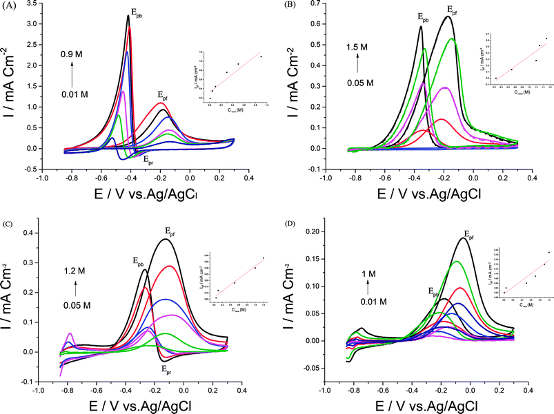
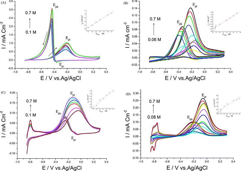
In order to achieve better electrocatalytic EOR, different parameters like NaOH and EtOH concentrations, scan rate, and upper potential limits were examined.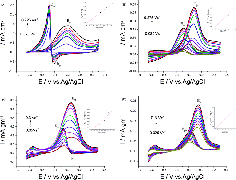 | ||
| Fig. 7 CVs of 0.5 M EtOH in 0.5 M NaOH at (A) Pd/p1,8-DAN, (B) Pt/p1,8-DAN, (C) Pd/Pt/p1,8-DAN/GC and (D) Pt/Pd/p1,8-DAN/GC catalyst electrodes at different scan rates. | ||
For each catalyst, the diffusion coefficient (D) was calculated according to the following Randles–Sevcik equation.50,51
| Ip = 2.69 × 10⁵n3/2AD1/2ν1/2C |
3.4. Chronoamperometry
The impact of poisoning the Pt and Pd NPs surfaces was analyzed using the chronoamperometry (CA) technique. A chronoamperometric study was carried out to better understand the electrocatalytic performance and stability of Pd/p1,8-DAN, Pt/p1,8-DAN, Pd/Pt/p1,8-DAN and Pt/Pd/p1,8-DAN catalysts towards EOR (figure not shown) where the potential was held at −0.02 V. By applying potential to each electrode, a steady decrease in current was observed within the initial couple of minutes for all catalysts, followed by the establishment of an almost steady current at longer times. The decrease in current with time could be ascribed to the intermediate poisoning species accumulated during the development of oxidation. The catalytic stability was found to follow the order Pt/Pd/p1,8-DAN > Pd/Pt/p1,8-DAN > Pt/p1,8-DAN > Pd/p1,8-DAN. The results suggested that the Pt/Pd/p1,8-DAN catalyst electrode shows higher catalytic activity and stability towards EOR, proving a superior tolerance to the carbonaceous intermediates generated during the oxidation process, as represented in Table 1.40,52,534. Conclusion
In this work, we have presented a support of a modified p1,8-DAN/GC electrode with Pt, Pd, Pt/Pd and Pd/Pt NPs for EOR. The performances of the resulting catalyst electrodes were considerably enhanced in terms of increasing the catalytic current and depressing the onset potential of EtOH oxidation. DEMS, CV and CA techniques were used to characterize the electrochemical behaviors of the prepared catalysts. Moreover, CA analysis was useful to prove the electrocatalytic performance, catalytic activity and stability of the prepared catalysts toward EOR. Experimental results revealed that the Pt/Pd/p1,8-DAN catalyst demonstrated considerably improved electrocatalytic activity and tolerance to CO poisoning (JPf/JPb = 2.6). Additionally, it revealed a superior electrochemically available surface area and faster charge transfer rate at the electrode/electrolyte interface than the other catalysts, making it a smart anode for the manufacture of an EtOH fuel cell.Conflicts of interest
There are no conflicts to declare.Acknowledgements
Authors would like to recognize Alexander Von Humboldt foundation for financial funding (Project No. 30260067) and Prof. H. Baltruschat for providing DEMS facilities.References
- K. Nishimura, K.-i. Machida and M. Enyo, J. Electroanal. Chem., 1988, 251, 103–116 CrossRef CAS.
- K. Nishimura, K.-i. Machida and M. Enyo, J. Electroanal. Chem., 1988, 251, 117–125 CrossRef CAS.
- K.-Y. Chan, J. Ding, J. Ren, S. Cheng and K. Y. Tsang, J. Mater. Chem., 2004, 14, 505–516 RSC.
- R. Ojani, J.-B. Raoof and S. R. H. Zavvarmahalleh, Electrochim. Acta, 2008, 53, 2402–2407 CrossRef CAS.
- L. An, T. S. Zhao, Q. X. Wu and L. Zeng, Int. J. Hydrogen Energy, 2012, 37, 14536–14542 CrossRef CAS.
- J. Sun, Y. Wang, C. Zhang, T. Kou and Z. Zhang, Electrochem. Commun., 2012, 21, 42–45 CrossRef CAS.
- A. A. Santasalo-Aarnio, PhD, Ex situ and in situ characterization of Direct Alcohol Fuel Cell anode materials, Aalto University publication series, 2012.
- Z. Qi, H. Geng, X. Wang, C. Zhao, H. Ji, C. Zhang, J. Xu and Z. Zhang, J. Power Sources, 2011, 196, 5823–5828 CrossRef CAS.
- A. A. Hathoot, Croat. Chem. Acta, 2011, 84, 469–473 CrossRef CAS.
- A. A. Hathoot, S. El-Maghrabi and M. Abdel-Azzem, Int. J. Electrochem. Sci., 2011, 6, 637–649 CAS.
- J.-B. Raoof, S. R. Hosseini and S. Rezaee, Electrochim. Acta, 2014, 141, 340–348 CrossRef CAS.
- A. A. Hathoot, U. S. Yousef, A. S. Shatla and M. Abdel-Azzem, Electrochim. Acta, 2012, 85, 531–537 CrossRef CAS.
- K. M. Hassan, A. A. Hathoot, W. F. D. Ashour and M. Abdel-Azzem, J. Solid State Electrochem., 2015, 19, 1063–1072 CrossRef CAS.
- A. A. Hathoot, K. M. Hassan, W. A. Essa and M. Abdel-Azzem, J. Iran. Chem. Soc., 2017, 14, 1789–1799 CrossRef CAS.
- M. Yovanovich, R. M. Piasentin, J. M. S. Ayoub, J. Nandenha, E. H. Fontes, R. F. B. de Souza, G. S. Buzzo, J. C. M. Silva, E. V. Spinace, M. H. M. T. Assumpcao, A. O. Neto and S. G. D. Silva, Int. J. Electrochem. Sci., 2015, 10, 4801–4811 CAS.
- Y. Wang, S. Zou and W.-B. Cai, Catalysts, 2015, 5, 1507 CrossRef CAS.
- W. Xie, F. Zhang, Z. Wang, M. Yang, J. Xia, R. Gui and Y. Xia, J. Electroanal. Chem., 2016, 761, 55–61 CrossRef CAS.
- N. F. Atta and M. F. El-Kady, Sens. Actuators, B, 2010, 145, 299–310 CrossRef CAS.
- M. M. Dimos and G. J. Blanchard, J. Phys. Chem. C, 2010, 114, 6019–6026 CAS.
- L. Dong, R. R. S. Gari, Z. Li, M. M. Craig and S. Hou, Carbon, 2010, 48, 781–787 CrossRef CAS.
- Y. Zhang, G. Chang, H. Shu, M. Oyama, X. Liu and Y. He, J. Power Sources, 2014, 262, 279–285 CrossRef CAS.
- H. Zhu, G. Li, X. Lv, Y. Zhao, T. Huang, H. Liu and J. Li, RSC Adv., 2014, 4, 6535 RSC.
- L. Liu, E. Pippel, R. Scholz and U. Gösele, Nano lett., 2009, 9, 4352–4358 CrossRef CAS PubMed.
- M. D. Obradović and S. L. Gojković, J. Solid State Electrochem., 2014, 18, 2599–2607 CrossRef.
- M. A. Kamyabi and M. Ahmadi, 11th Iranian Biennial Electrochemistry Seminar, University of Guilan, Rasht, September 9–11, 2014 Search PubMed.
- K. M. Hassan, G. M. Elhaddad and M. Abdel Azzem, J. Electroanal. Chem., 2014, 728, 123–129 CrossRef CAS.
- B. Habibi and S. Mohammadyari, Int. J. Hydrogen Energy, 2015, 40, 10833–10846 CrossRef CAS.
- Z. X. Liang, T. S. Zhao, J. B. Xu and L. D. Zhu, Electrochim. Acta, 2009, 54, 2203–2208 CrossRef CAS.
- R. K. Pandey and V. Lakshminarayanan, J. Phys. Chem. C, 2009, 113, 21596–21603 CAS.
- G. A. El-Nagar, A. M. Mohammad, M. S. El-Deab, T. Ohsaka and B. E. El-Anadouli, J. Power Sources, 2014, 265, 57–61 CrossRef CAS.
- D. A. J. Rand and R. T. Woods, J. Electroanal. Chem., 1971, 31, 29–38 CrossRef CAS.
- J. Solla-Gullon, A. Rodes, V. Montiel, A. Aldaz and J. Clavilier, J. Electroanal. Chem., 2003, 554–555, 273–284 CrossRef CAS.
- S. Dash and N. Munichandraiah, Electrochim. Acta, 2012, 80, 68–76 CrossRef CAS.
- A. E. Fetohi, R. Amin, R. A. Hameed and K. El-Khatib, Electrochim. Acta, 2017, 242, 187–201 CrossRef CAS.
- R. A. Hameed, J. Colloid Interface Sci., 2017, 505, 230–240 CrossRef PubMed.
- G. Hu, F. Nitze, H. R. Barzegar, T. Sharifi, A. Mikolajczuk, C.-W. Tai, A. Borodzinski and T. Wagberg, J. Power Sources, 2012, 209, 236–242 CrossRef CAS.
- A. M. Bonastre, Catalysts for Alcohol-Fuelled Direct Oxidation Fuel Cells, Platinum Met. Rev., 2013, 57, 297–301 CrossRef.
- A. Kumar and D. A. Buttry, Electrocatalysis, 2016, 7, 201–206 CrossRef CAS.
- G. F. Alvarez, M. Mamlouk, S. M. Senthil Kumar and K. P. Scott, J. Appl. Electrochem., 2011, 41, 925–937 CrossRef CAS.
- W. Du, K. E. Mackenzie, D. F. Milano, N. A. Deskins, D. Su and X. Teng, ACS Catal., 2012, 2, 287–297 CrossRef CAS.
- Z.-x. Cai, C.-c. Liu, G.-h. Wu, X.-m. Chen and X. Chen, Electrochim. Acta, 2013, 112, 756–762 CrossRef CAS.
- Y. Fan, Y. Zhao, D. Chen, X. Wang, X. Peng and J. Tian, Int. J. Hydrogen Energy, 2015, 40, 322–329 CrossRef CAS.
- H. Wang, K. Jiang, Q. Chen, Z. Xie and W.-B. Cai, Chem. Commun., 2016, 52, 374–377 RSC.
- S. Wang, S. P. Jiang, T. J. White, J. Guo and X. Wang, J. Phys. Chem. C, 2009, 113, 18935–18945 CAS.
- H. Ji, J. Frenzel, Z. Qi, X. Wang, C. Zhao, Z. Zhang and G. Eggeler, CrystEngComm, 2010, 12, 4059–4062 RSC.
- H. Yang, W. Vogel, C. Lamy and N. Alonso-Vante, J. Phys. Chem. B, 2004, 108, 11024–11034 CrossRef CAS.
- Y. Suo, L. Zhuang and J. Lu, Angew. Chem., 2007, 119, 2920–2922 CrossRef.
- X. Yang, Q. Yang, J. Xu and C.-S. Lee, J. Mater. Chem., 2012, 22, 8057–8062 RSC.
- R. Jiang, D. T. Tran, J. P. McClure and D. Chu, ACS Catal., 2014, 4, 2577–2586 CrossRef CAS.
- S. Azab and A. M. Fekry, RSC Adv., 2017, 7, 1118–1126 RSC.
- A. M. Fekry, Biosens. Bioelectron., 2017, 87, 1065–1070 CrossRef CAS PubMed.
- H. Rostami, T. Abdollahi, P. Mehdipour, A. A. Rostami and D. Farmanzadeh, Int. J. Hydrogen Energy, 2017, 42, 24713–24725 CrossRef CAS.
- M. Sedighi, A. A. Rostami and E. Alizadeh, Int. J. Hydrogen Energy, 2017, 42, 4998–5005 CrossRef CAS.
| This journal is © The Royal Society of Chemistry 2018 |

