
 Open Access Article
 This Open Access Article is licensed under a
 Creative Commons Attribution 3.0 Unported Licence
Improving the intrinsic thermal stability of the MAPbI3 perovskite by incorporating cesium 5-aminovaleric acetate†
Xue Liua,
Yulong Zhanga,
Jingchen Huaa,
Yong Penga,
Fuzhi Huang a,
Jie Zhonga,
Wangnan Lib,
Zhiliang Ku*ab and
Yi-bing Chengac
a,
Jie Zhonga,
Wangnan Lib,
Zhiliang Ku*ab and
Yi-bing Chengac
aState Key Laboratory of Advanced Technologies for Materials Synthesis and Processing, International School of Materials Science and Engineering, Wuhan University of Technology, 122 Luoshi Road, Wuhan, Hubei, P. R. China. E-mail: zhiliang.ku@whut.edu.cn
bHubei Key Laboratory of Low Dimensional Optoelectronic Material and Devices, Hubei University of Arts and Science, 296 Longzhong Road, Xiangyang, Hubei Province, P. R. China
cDepartment of Materials Science and Engineering, Monash University, Wellington Road, Clayton, VIC3800, Australia
First published on 19th April 2018
Abstract
Cesium 5-aminovaleric acetate (NH2C4H8COOCs) was used to improve the intrinsic thermal stability of the methylammonium lead triiodide (MAPbI3) perovskite. The corresponding carbon-based perovskite solar cells without encapsulation showed favourable stability at 100 °C for 500 h.
Next-generation solar cells have the prerequisite of low-cost and easy to fabricate are the prerequisites of next-generation printable solar cells. In recent years, printable solar cells based on ABX3 (where A is typically methylammonium (MA), formamidinium (FA), or Cs; B is Pb or Sn; and X is I, Br or Cl) perovskite-type light absorbers have attracted widespread attention for their high power conversion efficiencies (PCEs) combining with low processing costs. At present, the record PCE for any perovskite solar cell (PSC) is 22.7%,1 which is on a par with those of mainstream multi-crystalline silicon solar devices. Obviously, the high PCE together with easy fabrication procedures make PSCs a captivating device for future applications.
Typically PSCs need a vacuum system to evaporate a noble metal (Ag or Au) as the back contact. However, the use of vacuum system and expensive metal targets with high purity doesn't suit the purpose of low-cost printing. In this regard, the carbon-based perovskite solar cells,2 which substitute the noble metal electrode with a printable carbon electrode, have enormous potential for realizing the application of fully printed, low-cost photovoltaics. To date, many groups from all over the world have put much energy into the study of improving the performance of such PSCs with mesoporous carbon electrodes. Strategies including surface modification,3–5 materials engineering,6–11 solvent engineering12–14 and post-treatments15–17 have been applied in carbon-based PSCs for pursuing higher efficiencies. As a result, the reported PCE of carbon-based PSCs has increased rapidly from 6.6%2 to 17%18 in just a few years. And, at the same time, carbon-based PSCs have been reported that can be easily printed into large-scale modules.19 However, just like any other kind of PSC, long-term stability is still a problem for the final commercialization of this emerging photovoltaic technology.20 Solar modules are exposed to elevated temperatures during operation; hence as per the international standard (IEC 61646 climatic chamber tests), a solar panel must show thermal stability up to 85 °C.21 The formation energy for the MAPbI3 perovskite is 0.11–0.14 eV, which is close to 0.093 eV, suggesting possible degradation at a continuous exposure to a temperature of 85 °C. Recently, formamidinium cation (FA+)- and Cs+- based perovskites have demonstrated better thermal stability levels than has pure MAPbI3. However, FAPbI3 and CsPbI3 perovskites are more sensitive to humidity, which requires higher costs for encapsulation.22,23
In carbon-based PSCs, perovskite crystals are loaded in the mesopores, and their grain sizes are restricted by the pore size. In comparison to the perovskite crystals with large grains in traditional PSCs, perovskite crystals with small grains in carbon-based PSCs show much poorer heat tolerance. For this reason, all of the carbon-based PSCs using an MAPbI3 perovskite light absorber can only be annealed at 50–70 °C.2,4,8,16,19 From this perspective, enhancing the intrinsic heat tolerance of perovskite materials would be of great significance for the development of carbon-based PSCs.
Herein, we used cesium 5-aminovaleric acetate (NH2C4H8COOCs) as an additive of MAPbI3 perovskite, and found that CsxMA1−xPb(5-AVA)xI3−x perovskite showed high heat tolerance, even at 150 °C. Based on previous work,8 5-ammonium valeric acid (5-AVA) hydriodide (NH2C4H8COOH·HI), which was obtained from acid (HI) hydrolysis of 5-AVA, could create mixed-cation perovskite (5-AVA)x(MA)1−xPbI3 crystals with preferable stability in ambient air under full sunlight. Since 5-AVA is an amphipathic molecule, we employed CsOH to synthesize the alkaline hydrolysis product of 5-AVA (see ESI† for the synthesis details), aiming at combining the positive effects of the 5-AVA group and Cs+ cation in the MAPbI3 perovskite.
The molecular structures of (5-AVA) iodide and Cs-(5-AVA) acetate are shown in Fig. 1a. Via replacing 5% (in molar ratio) of MAI in the MAPbI3 perovskite with (5-AVA) iodide and Cs-(5-AVA) acetate, we obtained the (5-AVA)x(MA)1−xPbI3 perovskite and CsxMA1−xPb(5-AVA)xI3−x perovskite, respectively. Note that 5-AVA served as a cation in the (5-AVA)x(MA)1−xPbI3 perovskite, while in the CsxMA1−xPb(5-AVA)xI3−x perovskite, 5-AVA took the place of the I− anion. This little difference resulted in different solubilities of the (5-AVA)x(MA)1−xPbI3 perovskite and CsxMA1−xPb(5-AVA)xI3−x perovskite in γ-butyrolactone (GBL) solvent. As shown in Fig. 1b, the turbid (5-AVA)x(MA)1−xPbI3 perovskite solution (1 M in GBL) showed a lot of yellowish precipitate at room temperature. However, the CsxMA1−xPb(5-AVA)xI3−x perovskite solution was much clearer, indicating the CsxMA1−xPb(5-AVA)xI3−x perovskite to be more soluble than the (5-AVA)x(MA)1−xPbI3 perovskite. We attributed the good solubility of CsxMA1−xPb(5-AVA)xI3−x perovskite in GBL to the exposed amino group of the Cs-(5-AVA) acetate.
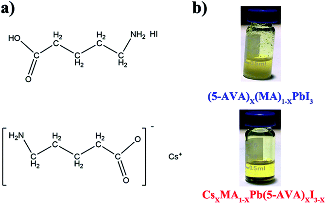 | ||
| Fig. 1 (a) The molecular structure of (5-AVA) iodide and Cs-(5-AVA) acetate. (b) Optical images of (5-AVA)x(MA)1−xPbI3 and CsxMA1−xPb(5-AVA)xI3−x perovskite solution at room temperature. | ||
X-ray diffraction (XRD) measurements were taken to identify the crystal structure of the as prepared perovskites. On glass substrate, both of the CsxMA1−xPb(5-AVA)xI3−x and (5-AVA)x(MA)1−xPbI3 perovskite patterns showed similar diffraction peaks at 14.18°, 23.5°, 24.5° 28.56° and 31.05°, indicating the same tetragonal MAPbI3 perovskite crystal structure.24 What's more, the intensities of the CsxMA1−xPb(5-AVA)xI3−x peaks were much stronger than those of the (5-AVA)x(MA)1−xPbI3 perovskite peaks. Since the two kinds of perovskite samples were fabricated and measured using the same conditions, we concluded the Cs-(5-AVA) acetate to be beneficial for the growth of the MAPbI3 perovskite (Fig. 2).
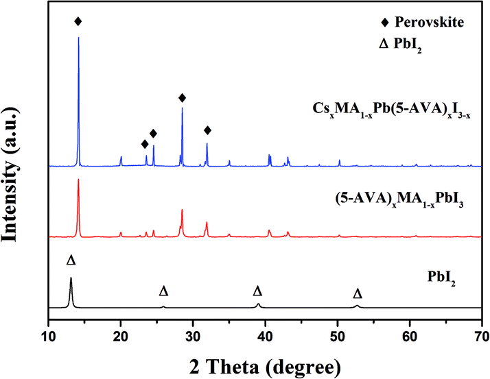 | ||
| Fig. 2 XRD patterns of the PbI2, (5-AVA)x(MA)1−xPbI3 and CsxMA1−xPb(5-AVA)xI3−x films on glass substrates. | ||
By using these two kinds of perovskite materials, we fabricated carbon-based PSCs according to the method reported previously.2 Briefly, by using the screen printing technique, mesoporous TiO2, ZrO2 and carbon films were successively deposited on the FTO substrates, which had been coated with compact TiO2 beforehand. And then, a perovskite light absorber was loaded by filling the precursor solution into the mesoporous carbon/ZrO2/TiO2 layers (see Fig. 3a). The microstructure of a cross-section of the as-prepared device was observed using SEM, and each layer showed well-defined boundaries and a uniform thickness (see Fig. 3b), and the distribution of the perovskite in the mesoporous films was homogenous (EDS images are shown in Fig. S1†). After the filling procedure, the devices were dried on a hot plate, and after the removal of GBL solvent, we finally obtained the carbon-based PSCs. For the sake of comparison, the drying temperature was set at 100 °C, which was much higher than the conventionally used temperature8 (50 °C).
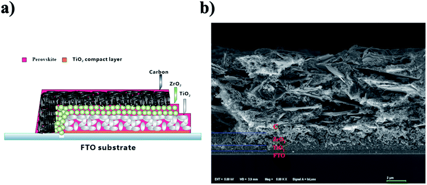 | ||
| Fig. 3 (a) Schematic structure of the carbon-based PSC. (b) SEM image from a cross-section of the carbon-based PSC. | ||
Two groups of the carbon-based PSCs (with each group consisting of eight devices) were fabricated by using the CsxMA1−xPb(5-AVA)xI3−x and (5-AVA)x(MA)1−xPbI3 perovskites, respectively. Under standard AM1.5 illumination (100 mW cm−2), the devices using the CsxMA1−xPb(5-AVA)xI3−x perovskite generally showed a higher PCE than did the (5-AVA)x(MA)1−xPbI3 perovskite. (Details of the photovoltaic parameters are summarized in Table S1.†) J–V curves of the corresponding best devices are shown in Fig. 4a. With the CsxMA1−xPb(5-AVA)xI3−x perovskite, the best device showed a photocurrent density (Jsc) of 20.59 mAcm−2 (with Jsc determined from the IPCE spectra in Fig. S2†), an open circuit voltage (Voc) of 893 mV, a fill factor (FF) of 0.66 and an overall PCE of 12.19%. In contrast, the best device using the (5-AVA)x(MA)1−xPbI3 perovskite showed a much lower PCE of 9.50% (Jsc = 16.78 mAcm−2, Voc = 830 mV and FF = 0.68). Moreover, the long-term stability levels of the best devices without encapsulation were determined at 100 °C in a glove box (see Fig. 4b). After 500 h, the PCE of the (5-AVA)x(MA)1−xPbI3-based device decayed gradually from 9.50% to 4.1%, i.e., a reduction of 56.8%. Surprisingly, the CsxMA1−xPb(5-AVA)xI3−x-based device maintained 88% (decay from 12.19% to 10.73%) of its initial PCE after 500 h, indicating favourable thermal stability at 100 °C.
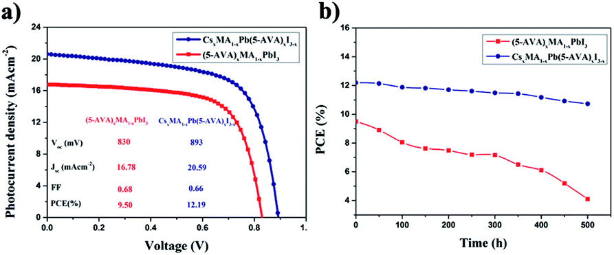 | ||
| Fig. 4 (a) J–V curves of the carbon-based PSCs with the (5-AVA)x(MA)1−xPbI3 and CsxMA1−xPb(5-AVA)xI3−x perovskites. (b) Long-term stability of the carbon-based PSCs stored at 100 °C in glove box. | ||
Further XRD measurements were taken to confirm the difference between the thermal stability of the (5-AVA)x(MA)1−xPbI3 perovskite and that of the CsxMA1−xPb(5-AVA)xI3−x perovskite. The (5-AVA)x(MA)1−xPbI3 perovskite, after having been heated on a hot plate at 75 °C for 24 h, yielded an XRD pattern showing a small peak at 2θ = 12.63°, indicating that part of the perovskite was decomposed into PbI2. As the temperature was increased, the intensity of the PbI2 diffraction peak became increasingly stronger, and the colour of (5-AVA)x(MA)1−xPbI3 perovskite film on glass gradually changed from black to yellow (see Fig. 5a). However, compared with the (5-AVA)x(MA)1−xPbI3 perovskite, the CsxMA1−xPb(5-AVA)xI3−x perovskite displayed a much lower thermal decomposition rate. As shown in Fig. 5b, even after having been heated at 150 °C for 24 h, most of the CsxMA1−xPb(5-AVA)xI3−x perovskite still kept the perovskite phase (see Fig. 5b).
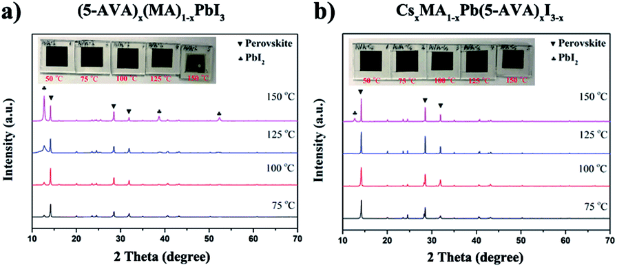 | ||
| Fig. 5 XRD patterns and optical images (inset) of (a) (5-AVA)x(MA)1−xPbI3 and (b) CsxMA1−xPb(5-AVA)xI3−x perovskite films exposed on a hot plate to various temperatures each for 24 h. | ||
To further identify any possible effects of the (5-AVA) anion and Cs cation on the thermal stability of the MAPbI3 perovskite, we also compared the decomposition process of MAPb(5-AVA)xI3−x with that of CsxMA1−xPbI3−x (see Fig. S3†). The XRD results showed that including 5% Cs+ individually or 5% (5-AVA)− individually in the MAPbI3 perovskite sample did not much enchance the thermal stability of the sample. Hence, we attributed the good thermal stability of the CsxMA1−xPb(5-AVA)xI3−x perovskite to the unique Cs-(5-AVA) acetate additive. Since the 5-AVA group can act as a templating agent in perovskites8,25,26 and the Cs+ cation has a strong bonding energy with the I− anion, the migration of ions in the CsxMA1−xPb(5-AVA)xI3−x perovskite could be suppressed by the 2D/3D interfaces27 and the high migration activation energy of the inorganic cation.28
Conclusions
In summary, we have developed a novel CsxMA1−xPb(5-AVA)xI3−x perovskite by incorporating the Cs-(5-AVA) acetate into the MAPbI3 perovskite. Carbon-based PSCs using such CsxMA1−xPb(5-AVA)xI3−x perovskites exhibited a favourable PCE of 12.19%. Moreover, after having been stored at 100 °C in a glove box for 500 h, the device still maintained 88% of its initial PCE. The XRD results showed the CsxMA1−xPb(5-AVA)xI3−x perovskite to have a thermal decomposition rate much lower than that of the mixed-cation (5-AVA)x(MA)1−xPbI3 perovskite. Combining Cs+ with an alkyl chain to suppress the ion migration in MAPbI3 perovskites could be a new strategy for enhancing the thermal stability of PSCs.Conflicts of interest
There are no conflicts to declare.Acknowledgements
The authors acknowledge the financial support of the National Natural Science Foundation of China (NSFC 51702243, 51402115, 51672202), Hubei Provincial Natural Science Foundation of China (2016CFB464), the Technological Innovation Key Project of Hubei Province (2016AAA041), the Fundamental Research Funds for the Central Universities (WUT: 2016IVA093, 2016IVA089, 2016IVA085, 2016III030, 2017III022) and the Hubei Key Laboratory of Low Dimensional Optoelectronic Material and Devices (HLOM151001).Notes and references
- N. R. E. L. N. Best Research Cell_Efficiencies, October. 2017, https://www.nrel.gov/pv/assets/images/efficiency-chart.png.
- Z. L. Ku, Y. G. Rong, M. Xu, T. F. Liu and H. W. Han, Sci. Rep., 2013, 3, 3132 Search PubMed.
- J. Ryu, K. Lee, J. Yun, H. Yu, J. Lee and J. Jang, Small, 2017, 13, 1701225 Search PubMed.
- F. Behrouznejad, C.-M. Tsai, S. Narra, E. W. G. Diau and N. Taghavinia, ACS Appl. Mater. Interfaces, 2017, 9, 25204–25215 Search PubMed.
- L. Liu, A. Mei, T. Liu, P. Jiang, Y. Sheng, L. Zhang and H. Han, J. Am. Chem. Soc., 2015, 137, 1790–1793 Search PubMed.
- V. Kapoor, A. Bashir, L. J. Haur, A. Bruno, S. Shukla, A. Priyadarshi, N. Mathews and S. Mhaisalkar, Energy Technol., 2017, 5, 1880–1886 Search PubMed.
- M. Hu, L. Liu, A. Mei, Y. Yang, T. Liu and H. Han, J. Mater. Chem. A, 2014, 2, 17115–17121 Search PubMed.
- A. Mei, X. Li, L. Liu, Z. Ku, T. Liu, Y. Rong, M. Xu, M. Hu, J. Chen, Y. Yang, M. Gratzel and H. Han, Science, 2014, 345, 295–298 Search PubMed.
- X. Zheng, H. Chen, Q. Li, Y. Yang, Z. Wei, Y. Bai, Y. Qiu, D. Zhou, K. S. Wong and S. Yang, Nano Lett., 2017, 17, 2496–2505 Search PubMed.
- T. A. N. Peiris, A. K. Baranwal, H. Kanda, S. Fukumoto, S. Kanaya, L. Cojocaru, T. Bessho, T. Miyasaka, H. Segawa and S. Ito, Nanoscale, 2017, 9, 5475–5482 RSC.
- Y. Rong, X. Hou, Y. Hu, A. Mei, L. Liu, P. Wang and H. Han, Nat. Commun., 2017, 8, 14555 CrossRef PubMed.
- J. Chen, Y. Xiong, Y. Rong, A. Mei, Y. Sheng, P. Jiang, Y. Hu, X. Li and H. Han, Nano Energy, 2016, 27, 130–137 CrossRef CAS.
- C.-Y. Chan, Y. Wang, G.-W. Wu and E. Wei-Guang Diau, J. Mater. Chem. A, 2016, 4, 3872–3878 CAS.
- H. Chen, Z. Wei, H. He, X. Zheng, K. S. Wong and S. Yang, Adv. Energy Mater., 2016, 6, 1502087 CrossRef.
- Y. Zhang, J. Wang, X. Liu, W. Li, F. Huang, Y. Peng, J. Zhong, Y. Cheng and Z. Ku, RSC Adv., 2017, 7, 48958–48961 RSC.
- S. G. Hashmi, D. Martineau, M. I. Dar, T. T. T. Myllymaki, T. Sarikka, V. Ulla, S. M. Zakeeruddin and M. Gratzel, J. Mater. Chem. A, 2017, 5, 12060–12067 CAS.
- L. Hong, Y. Hu, A. Mei, Y. Sheng, P. Jiang, C. Tian, Y. Rong and H. Han, Adv. Funct. Mater., 2017, 27, 1703060 CrossRef.
- S. Liu, W. Huang, P. Liao, N. Pootrakulchote, H. Li, J. Lu, J. Li, F. Huang, X. Shai, X. Zhao, Y. Shen, Y.-B. Cheng and M. Wang, J. Mater. Chem. A, 2017, 5, 22952–22958 CAS.
- A. Priyadarshi, L. J. Haur, P. Murray, D. Fu, S. Kulkarni, G. Xing, T. C. Sum, N. Mathews and S. G. Mhaisalkar, Energy Environ. Sci., 2016, 9, 3687–3692 CAS.
- J. S. Shaikh, N. S. Shaikh, A. D. Sheikh, S. S. Mali, A. J. Kale, P. Kanjanaboos, C. K. Hong, J. H. Kim and P. S. Patil, Mater. Des., 2017, 136, 54–80 CrossRef CAS.
- B. Conings, J. Drijkoningen, N. Gauquelin, A. Babayigit, J. D'Haen, L. D'Olieslaeger, A. Ethirajan, J. Verbeeck, J. Manca, E. Mosconi, F. D. Angelis and H.-G. Boyen, Adv. Energy Mater., 2015, 5, 1500477 CrossRef.
- B. Li, Y. Li, C. Zheng, D. Gao and W. Huang, RSC Adv., 2016, 6, 38079–38091 RSC.
- T.-B. Song, Q. Chen, H. Zhou, C. Jiang, H.-H. Wang, Y. Yang, Y. Liu, J. You and Y. Yang, J. Mater. Chem. A, 2015, 3, 9032–9050 CAS.
- T. Baikie, Y. Fang, J. M. Kadro, M. Schreyer, F. Wei, S. G. Mhaisalkar, M. Graetzel and T. J. White, J. Mater. Chem. A, 2013, 1, 5628 CAS.
- A. K. Baranwal, S. Kanaya, T. A. Peiris, G. Mizuta, T. Nishina, H. Kanda, T. Miyasaka, H. Segawa and S. Ito, ChemSusChem, 2016, 9, 2604–2608 CrossRef CAS PubMed.
- G. Grancini, C. Roldán-Carmona, I. Zimmermann, E. Mosconi, X. Lee, D. Martineau, S. Narbey, F. Oswald, F. De Angelis, M. Graetzel and M. K. Nazeeruddin, Nat. Commun., 2017, 8, 15684 CrossRef CAS PubMed.
- X. Xiao, J. Dai, Y. Fang, J. Zhao, X. Zheng, S. Tang, P. N. Rudd, X. C. Zeng and J. Huang, ACS Energy Lett., 2018, 3, 684–688 CrossRef CAS.
- D. Pan, Y. Fu, J. Chen, K. J. Czech, J. C. Wright and S. Jin, Nano Lett., 2018, 18, 1807–1813 CrossRef CAS PubMed.
Footnote |
| † Electronic supplementary information (ESI) available: Experimental details, EDS mapping of the carbon-based PSCs, IPCE of the champion devices. See DOI: 10.1039/c7ra13611k |
| This journal is © The Royal Society of Chemistry 2018 |