
 Open Access Article
 This Open Access Article is licensed under a Creative Commons Attribution-Non Commercial 3.0 Unported Licence
Anisotropic architecture and electrical stimulation enhance neuron cell behaviour on a tough graphene embedded PVA: alginate fibrous scaffold†
Nasim Golafshana,
Mahshid Kharaziha *a,
Mohammadhossein Fathia,
Benjamin L. Larsonb,
Giorgio Giatsidisc and
Nafiseh Masoumi*bd
*a,
Mohammadhossein Fathia,
Benjamin L. Larsonb,
Giorgio Giatsidisc and
Nafiseh Masoumi*bd
aDepartment of Materials Engineering, Isfahan University of Technology, Isfahan 84156-83111, Iran, Email: kharaziha@cc.iut.ac.ir
bHarvard-MIT Division of Health Sciences and Technology, Koch Institute for Integrative Cancer Research, Massachusetts Institute of Technology, Cambridge, MA 02139, USA. E-mail: masoumi@mit.edu
cDepartment of Surgery, Brigham and Women Hospital, Harvard Medical School, Boston, MA 02120, USA
dCardiac Surgery Department, Boston Children's Hospital, Harvard Medical School, Boston, MA 02120, USA
First published on 8th February 2018
Abstract
Tough scaffolds comprised of aligned and conductive fibers are promising for peripheral nerve regeneration due to their unique mechanical and electrical properties. Several studies have confirmed that electrical stimulation can control the axonal extension in vitro. However, the stimulatory effects of scaffold architecture and electrical stimulation have not yet been investigated in detail. Here, we assessed a comparison between aligned and random fibers made of graphene (Gr) embedded sodium alginate (SA) polyvinyl alcohol (PVA) (Gr-AP scaffolds) for peripheral nerve engineering. The effects of applied electrical stimulation and orientation of the fabricated fibers on the in vitro attachment, alignment, and proliferation of PC12 cells (a rat neuronal cell line) were investigated. The results revealed that the aligned fibrous Gr-AP scaffolds closely mimicked the anisotropic structure of the native sciatic nerve. Aligned fibrous Gr-AP scaffolds significantly improved mechanical properties as well as cell-scaffold integration compared to random fibrous scaffolds. In addition, electrical stimulation significantly improved PC12 cell proliferation. In summary, our findings revealed that aligned fibrous Gr-AP scaffolds offered superior mechanical characteristics and structural properties that enhanced neural cell–substrate interactions, resulting in a promising construct for nerve tissue regeneration.
1. Introduction
Peripheral nerve injuries caused by trauma or oncologic resection are a frequent cause of significant functional impairment and long-term disability in patients due to the limited intrinsic capacity of nerves to repair after damage.1 Currently, few effective solutions are available to successfully promote peripheral nerve regeneration and functional recovery,2 aside from autologous nerve grafting which results in donor site morbidity, loss of sensation, and neuroma formation. Tissue engineering is a promising strategy to regenerate human tissues or organs3 with the aim to restore and maintain the functionality of damaged tissues.3,4 Tissue engineered nerve scaffolds, such as conduits, have shown the potential to promote nerve regeneration in clinical trials and might offer a valuable alternative to autologous grafts in the future.5–7 However, these materials have not been able to match the properties and in vivo efficacy of autologous nerves, suggesting the need for further research and optimization. For nerve regeneration, scaffolds require fundamental properties including biocompatibility, biodegradability, physiologically relevant flexibility and mechanical strength, hydrophilicity to promote cell adhesion and be semipermeability.8–12 The anisotropic structure of the substratum has proven to be an important property of the tissue, promoting neurite outgrowth after peripheral nerve injuries.11 This alignment aids cell migration and organization along the nerve fiber preferred direction. Electrospun, aligned fibrous scaffolds have been widely used for nerve tissue regeneration due to their structural similarity to native extracellular matrix (ECM) architecture.10,11,13,14 For instance, Gupta et al.14 have developed aligned and random polycaprolactone (PCL)/gelatin based fibrous scaffolds and showed that aligned fibers could control Schwann cell function, leading to growth of regenerating axons in nerve tissue.Another strategy that has been explored in nerve tissue engineering is the use of scaffolds with electrically conductive properties to transmit electro-chemical signals to direct the proximal outgrowth axons along the desired path.15,16 Therefore, the application of conductive materials to support the electrical conduction of damaged or defective nerves has been shown to be effective for nervous system regeneration.8 It has been shown that aligned and conductive fibrous scaffolds could provide better contact guidance effects in neurite outgrowth.10,13,17–19
Among various conductive materials, graphene based nanomaterials are promising for neural tissue engineering applications.20–22 Graphene based nanomaterials have advantages including appropriate electrical conductivity, biocompatibility and high electrical stability, and have been shown to improve the mechanical properties of polymeric hybrid scaffolds as well.23 Previous studies used polymers with graphene-based nanomaterials that possess the desired material properties to obtain hybrid composites with superb material properties and electrical conductivity. Previously, we optimized the concentration of graphene nanosheets to obtain maximum conductivity and minimum cell-toxicity in hybrid PVA-sodium alginate scaffolds.24 We found that a hybrid scaffold consisting of 1% graphene (Gr-AP) could provide optimum chemical and electrical properties for neural cell proliferation. However, based on observations from prior reports,12,19 fiber alignment could lead to optimal cell alignment in guiding orientation of axonal growth.
In the present study, we developed aligned Gr-AP fibrous scaffolds using a modified electrospinning approach. To mimic the anisotropic structure of the native peripheral nervous system, aligned fibers were produced using a manual-rotating collector with a specifically designed cage apparatus. The scaffolds were seeded and cultured under electrical stimulation to obtain optimum neural regeneration conditions. To the best of our knowledge, this is the first attempt to evaluate the effects of electrical stimulation on the on the functionality of PC12 cells cultured on graphene based aligned and conductive fibrous scaffolds. This tough and flexible hybrid Gr-AP fibrous scaffold with enhanced electrophysiological functionalities has the potential to guide the topographical, mechanical and electrical signals to support in situ nerve regeneration.
2. Experimental
2.1. Materials
Polyvinyl alcohol (PVA, Mw = 72![[thin space (1/6-em)]](https://www.rsc.org/images/entities/char_2009.gif) 000) and sodium alginate (SA, Mw = 80000–120000) were purchased from Sigma Aldrich Co, St Louis, MO, USA and graphene (less than 32 layers, purity >99.5%) was purchased from Nanosany Corporation, Iran. PC12 cells were obtained from the Pasteur Institute, Iran (NCBI code: C153) for cell culture studies. Dulbecco's Modified Eagle's Medium Hi-glutamine (DMEM-HI), trypsin–EDTA and antibiotics were obtained from Bioidea, Iran; fetal bovine serum (FBS) was obtained from GIBCO, Gaithersburg, MD, USA; and horse serum (HS) was purchased from Bahar Afshan, Iran. Paraformaldehyde (PF), DAPI (40,6-diamidino-2-phenylindole), and glutaraldehyde were obtained from Sigma Aldrich Co.
000) and sodium alginate (SA, Mw = 80000–120000) were purchased from Sigma Aldrich Co, St Louis, MO, USA and graphene (less than 32 layers, purity >99.5%) was purchased from Nanosany Corporation, Iran. PC12 cells were obtained from the Pasteur Institute, Iran (NCBI code: C153) for cell culture studies. Dulbecco's Modified Eagle's Medium Hi-glutamine (DMEM-HI), trypsin–EDTA and antibiotics were obtained from Bioidea, Iran; fetal bovine serum (FBS) was obtained from GIBCO, Gaithersburg, MD, USA; and horse serum (HS) was purchased from Bahar Afshan, Iran. Paraformaldehyde (PF), DAPI (40,6-diamidino-2-phenylindole), and glutaraldehyde were obtained from Sigma Aldrich Co.
2.2. Development of aligned fibrous Gr-AP scaffolds
Prior to electrospinning, 1 wt% graphene: SA:PVA (Gr-AP) suspension was prepared. Briefly, SA was dissolved with the concentration of 4 wt% in distilled water and glycerol (4:3 volume ratio). Separately, PVA solution with 8 wt% concentration was prepared in distilled water. After mixing PVA and SA solutions at 80:20 volume ratio, 1 wt% graphene and 0.5 wt% Triton X-100 were added to the polymeric solution to enhance spinnability, subsequently. The polymer suspensions were sonicated for 30 min at room temperature to provide a homogenous dispersion of graphene nanosheets and subsequently fed into a 1 ml syringe with a 23 G blunt stainless steel needle. The electrospinning process was performed at constant voltage and flow rate at the tip-to-collector distance of 18 kV, 0.12 ml h−1 and 10 cm, respectively. In order to fabricate aligned scaffolds, a cage cylinder made of copper was used as a collector and established to guide the fibers with high accuracy (ESI Fig. S1†). The distance between the cage bars was set to 1 cm and the collector was rotated at 800 rpm. Random fibrous scaffolds were deposited on an aluminium foil slide placed on the collector plate. Aligned and random fibrous scaffolds were termed A:Gr-AP and R:Gr-AP, respectively.
Finally, in order to crosslink the scaffolds, they were placed at 80 °C overnight and subsequently immersed in methanol for 1 h to crosslink PVA. In order to crosslink SA, the scaffolds were immersed in 2 wt% CaCl2 solution for 1 h and finally dried overnight under vacuum prior to further characterization and biological experiments.
2.3. Characterization of aligned fibrous Gr-AP scaffolds
The surface morphology of hybrid A:Gr-AP and R:Gr-AP fibrous scaffolds were studied using a scanning electron microscope (XL30 SEM, Philips, Netherlands), after sputter coating with gold. The average diameter of fibers was analysed from the SEM images (n = 20) using image analysis software. Additionally, the fiber orientation of each scaffold was evaluated using MATLAB (MathWorks Inc., Natick, MA, USA) before and after the crosslinking process. Fast Fourier Transform (FFT) analysis was used to quantify the fiber orientation according to previous procedures.25 According to this analysis, the orientation index approached 90° for random fibers orientations; while for aligned fibers, the orientation index approached zero.26 Furthermore, the graphene distribution within the A:Gr-AP fibrous scaffolds was assessed using a transmission electron microscope (TEM) (Philips EM208S 100 kV). The functional groups on the surface of the fibrous scaffolds were identified using Fourier transformer infrared (FTIR) spectroscopy performed over a range of 600–4000 cm−1 and resolution of 2 cm−1. In addition, X-ray diffraction (XRD, X′ Pert Pro X-ray diffractometer, Phillips) technique was carried out with Cu Kα radiation (λ = 0.154 nm, 40 kV, 40 mA). The water contact angle of the scaffolds (n = 3) was measured by sessile drop method with a G10 contact angle goniometer at room temperature. A water droplet (4 μl) was placed on the scaffold surfaces and the contact angle was measured after 0, 10 and 20 s. The measured contact angle value reflects the hydrophilicity of the scaffolds.The tensile properties of hybrid scaffolds with length: 10 mm × 40 mm were determined using uniaxial tensile tester machine (Hounsfield H25KS, Shakopee, MN, USA) with a cell load capacity of 10 N at a rate of 3 mm min−1. Before mechanical testing, the samples were soaked in PBS for 1 day at room temperature. The stress–strain curves were plotted (n = 5) and energy per volume (toughness) and elastic modulus were obtained. To observe the mechanical behavior of aligned fibrous scaffolds, tensile samples were prepared parallel and perpendicular to the direction of the uniaxial oriented fibers.
2.4 Cell culture
Before cell seeding, the scaffolds were sterilized for 30 min in 70% (v/v) ethanol and 2 h under ultraviolent (UV) light and subsequently immersed in complete culture medium overnight prior to cell seeding in 24-well plates. The PC12 cell-line was cultured in DMEM-HI supplemented with 10% (v/v) horse serum (HS), 5% (v/v) fetal bovine serum (FBS), and 1% (v/v) penicillin/streptomycin at 37 °C in a humidified atmosphere containing 5% CO2. The PC12 cells were seeded on the scaffolds (n = 3) and tissue culture plates as a control with a density of 2 × 10⁵ cells per well. Cells were incubated at 37 °C under 5% CO2 for 7 days and medium was changed every three days.The spreading of PC12 cells cultured on the scaffolds for 7 days was evaluated by SEM. After 3 h fixation with 2.5% (v/v) glutaraldehyde (Sigma Aldrich Co), the samples were rinsed with PBS and dehydrated in graded concentrations of ethanol 30, 70, 90, 96 and 100% (v/v) for 10 min. Finally, they were air dried, gold-coated and evaluated with SEM imaging.
The resazurin assay is based on the reduction of resazurin, a normally non-fluorescent compound, to resorufin, a fluorescent metabolite, due to the highly reducing milieu of living cells.27 After discarding the culture medium from samples, resazurin solution (concentration of 10 μg ml−1 in complete medium) was added to each sample and kept in an incubator for 4 h, until the color of the resazurin solution was changed. Subsequently, the absorbance of each solution was read at 630 nm using a microplate reader.
2.5. Statistical analysis
Statistical analysis was performed with Graphpad Prism 6, to evaluate the differences in each group; all data were expressed as the mean ± SD. The experimental values were analyzed using one-way ANOVA and student's t-test. The statistical significance was defined as p < 0.05 and p < 0.01, as noted.3. Result and discussion
3.1. Fabrication and characterization of the Gr-AP scaffolds
Treatment for peripheral nerve injuries requires additional medical therapy, in order to promote effective nerve regeneration for nerve defects larger than 2–3 cm.11,14,29,30 Currently, use of autologous nerve grafts are the gold standard. However, the procedure creates donor site morbidity, and is not always possible. Alternatives includes cadaveric nerve donor tissue or nerve conduits. Development of a functionalized nerve conduit, using conductive nanoparticles and electrical signal propagation along the scaffold to improve nerve regeneration could offer a valuable potential solution for peripheral nerve injury. According to our previous research,24 randomly oriented Gr-AP fibrous scaffolds were developed and optimized for electrical conductance, obtained at 1 wt% graphene content. In order to better mimic native nerve tissue, aligned Gr-AP fibrous scaffolds were fabricated by electrospinning using a cage collector (Fig. 1A and ESI Fig. S1†) rotating at 3750 rpm. As shown in Fig. 1B and D, aligned fibrous scaffolds consisting of graphene nanosheets were developed and physical and chemical interactions between polymeric matrix and graphene nanosheets confirmed equally distributed graphene within the alginate-PVA matrix formed after the crosslinking process.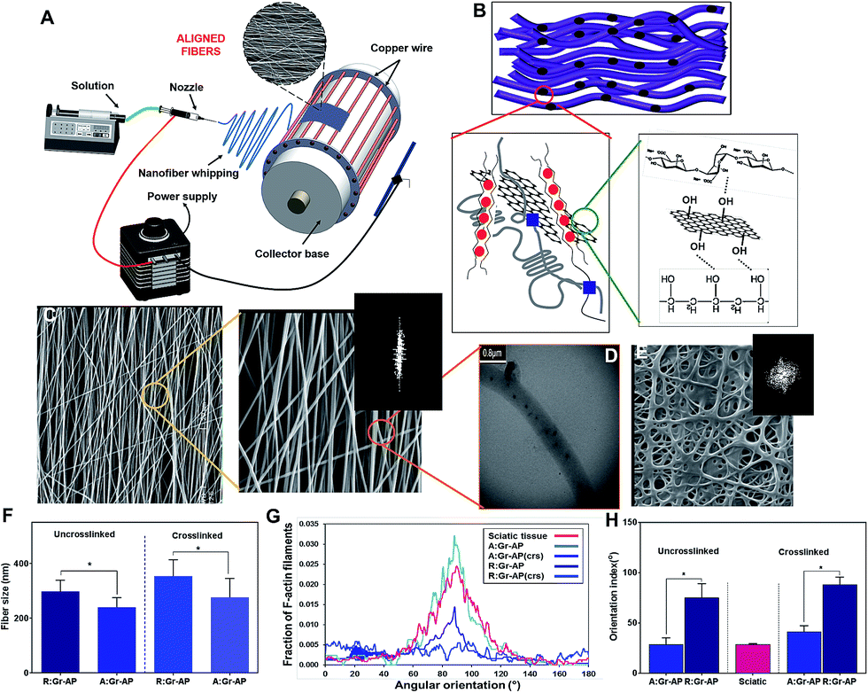 | ||
| Fig. 1 Structural properties of aligned fibrous Gr-AP (A:Gr-AP) scaffolds: (A) schematic of electrospinning approach for the controlled design of aligned oriented fibrous scaffolds. (B) Representation of the graphene distribution and interaction with AP polymeric matrix after crosslinking process. (C) SEM images (at two different magnifications) and FFT image of aligned fibrous scaffold before crosslinking process. (D) TEM image of well-distributed graphene within AP fibers. (E) SEM and FFT image of random fibrous Gr-AP scaffold, before crosslinking process. (F) The average fiber size of aligned and random fibrous scaffolds before and after crosslinking. (G) Radial plot of the relative pixel intensity at a radius versus the angle (°) caused by the inherent symmetry of the raw 2-D FFT output. (H) The average orientation index of fibrous scaffolds, revealing that aligned fibers enhanced fiber orientation (*P < 0.05). | ||
As shown in Fig. 1C, A:Gr-AP scaffolds, depicted in two different magnifications, consisted of highly uniform fibers without any observable beading. TEM imaging of A:Gr-AP (Fig. 1D) also confirmed that individual graphene nanosheets with a size of 88 ± 13 nm were well distributed in the polymeric matrix without any agglomeration, confirming the mono-dispersion of graphene nanosheets within the AP matrix. Based on percolation theory,31 the uniform distribution of graphene nanosheets in polymeric fibers could result in the formation of a conductive network during electrical stimulation. In order to better clarify the role of fiber alignment on cell behavior, randomly oriented fibrous Gr-AP (R:Gr-AP) scaffold was fabricated using the electrospinning system with an aluminium plate as a collector. SEM imaging of R:Gr-AP revealed the formation of uniform and bead-free fibers with interconnected pores (Fig. 1E). The significantly smaller fiber size of the A:Gr-AP scaffold, 240.1 ± 35.3 nm, compared to R:Gr-AP scaffold with fiber size of 296.8 ± 41.8 nm (Fig. 1F) could be due to enhanced surface tension in the retractable fibers on the surface of the rotating drum. Similar results were reported previously in the study of the development of poly(glycerol sebacate) (PGS):gelatin fibrous scaffolds.32 We showed that the fiber size of gelatin scaffolds decreased from 510 nm to 390 nm when the architecture of fibers changed from random to aligned. SEM images confirmed the arrangement of fibers resulted in reduced pore size of crosslinked A:Gr-AP from 1.37 ± 0.6 μm to 0.64 ± 0.03 μm. However, the pore size of the scaffolds cannot exceed a certain size, to potentially avoid inflammatory cells from migrating into the lumen, and to diminish the diffusion of growth factors out of the guide lumen.33–35 A previous study confirmed that the ideal scaffolds for nerve tissue engineering should have nano to micro-pore sizes (50 nm to 5 μm) to allow diffusion of oxygen, nutrients, neurotrophic factors such as growth factors, and prevent the infiltration of fibrous tissues.29
To reduce the degradation rate of the fibrous scaffold in biological media and eventually in vivo, the scaffolds were crosslinked in two steps of physical and chemical processes. PVA was covalently crosslinked using heat treatment and methanol followed by ionically crosslinking alginate using a CaCl2 solution according to our previously reported method.24 SEM images of crosslinked Gr-AP scaffolds (ESI Fig. S2†) also show the variations in the morphology of scaffolds and increased average fiber diameter following crosslinking. The average fiber diameter of A:Gr-AP scaffold was enhanced 1.8 times to 555 ± 22 nm (Fig. 1F). Such observations are in agreement with previous studies conducted on PGS-gelatin32 and CNT-PGS:gelatin (CNT-PG)26 where the average fiber diameter of the crosslinked 1.5% CNT-PG scaffold was in the range of 210 nm, while the average fiber size of 1.5% CNT-PG scaffold was approximately 167 nm.26 This could be due to the hydrophilicity of the polymeric matrix absorbing water and swelling of the fibers during the crosslinking process.36–38 Similar to uncrosslinked scaffolds, the average fiber sizes of the crosslinked scaffolds significantly decreased through changing the architecture of scaffolds from random (353 ± 60 nm) to aligned (276 ± 69 nm) (Fig. 1F).
The degree of alignment in Gr-AP scaffolds as a fundamental feature affecting the organization of the cells was also estimated using an FFT-based analysis technique based on the SEM images (Fig. 1C and E and ESI Fig. S2†). Angular increments were measured and the orientation index (OI) was calculated using these curves (Fig. 1G), representing 50% of the total area under the fraction curve centered at the angle, correlated with the highest frequency (Fig. 1H). It has been shown that a lower orientation index correlates with a thinner mean scattering and increase in parallel fibers.39 Results demonstrated that the orientation index of A:Gr-AP (OI = 28.7°) was lower than that of R:Gr-AP (75°). The orientation of nerve fibers (Fig. 1G and H) was also measured using FFT analysis of histological images of a native sciatic nerve.40 Our results revealed that the orientation index value of the A:Gr-AP scaffold closely matched that of native nerve fibers (OI = 26.8°). Therefore, A:Gr-AP scaffolds structurally mimic the native structures suggesting that this may enhance the alignment of PC12 cells.
In order to evaluate the hydrophilicity of the scaffolds, the water contact angle values of the randomly oriented and aligned fibrous Gr-AP scaffolds were measured after 0, 10 and 20 s, and the averaged angles were estimated at 25.9 ± 0.6° and 20.6 ± 0.8° after 20 s (p < 0.05) (ESI Fig. S3†), respectively. Generally, water contact angle is affected by both surface chemical and physical properties. Both PVA and alginate polymers consist of functional groups such as hydroxyl (OH) and carboxyl (COO−) with high affinity for interaction with water molecules.41 Therefore, aligned and random fibrous scaffolds were relatively hydrophilic, as reported previously.42,43 However, the significant difference between the water contact angles of these two scaffolds could correspond to their different structural properties. The increase in the wettability of aligned fibrous scaffolds compared to random one might be related to the acicular shape of the pores in the A:Gr-AP scaffold (ESI Fig. S2 and S3†) which facilitate the spreading of water drops on the surface. This result suggested that an aligned, oriented surface could be an appropriate option for fabricating polymeric biomedical scaffolds with strong wettability properties.29,44
Chemical characterization of the crosslinked scaffolds was conducted using FTIR analysis (Fig. 2A) and XRD patterns (Fig. 2B). FTIR spectra of PVA, alginate and graphene were also provided to evaluate the internal interaction between components. The typical peak of PVA was a broad peak covering the wavenumber 780 cm−1, corresponding to the vibration of the O–H group. The absorption peak centering at 846 cm−1 was related to the vibration of the C–H group and two broad peaks covering the range of 1041 and 1093 cm−1 were corresponded to the stretching vibration of the C–O and C–O–C groups.45 Moreover, pure alginate powder revealed a sharp asymmetric carboxylate band at 1612 cm−1 and a broad hydroxyl band at 3296 cm−1.46 The FTIR spectrum of Gr-AP fibrous scaffolds consisted of both peaks related to PVA and alginate. Compared to FTIR spectra of alginate and PVA, FTIR spectrum of the Gr-AP scaffold revealed the formation of hydrogen bonding between the hydroxyl groups of PVA and alginate which moderated the interaction between alginate macromolecules and amended the electro-spinnability of alginate with PVA.47,48 The O–H and C–H bonds at 846 cm−1 and 1093 cm−1, respectively, relating to PVA polymer, shifted to lower wavenumbers (indicated by red arrows) and the intensity of some absorption bands of PVA (in 846, 1093, 1250 and 3320 cm−1 related to C–H, C–O–C, C–H and O–H bonding) were reduced confirming the formation of hydrogen bonding between graphene and polymeric matrices after the two-step crosslinking process.
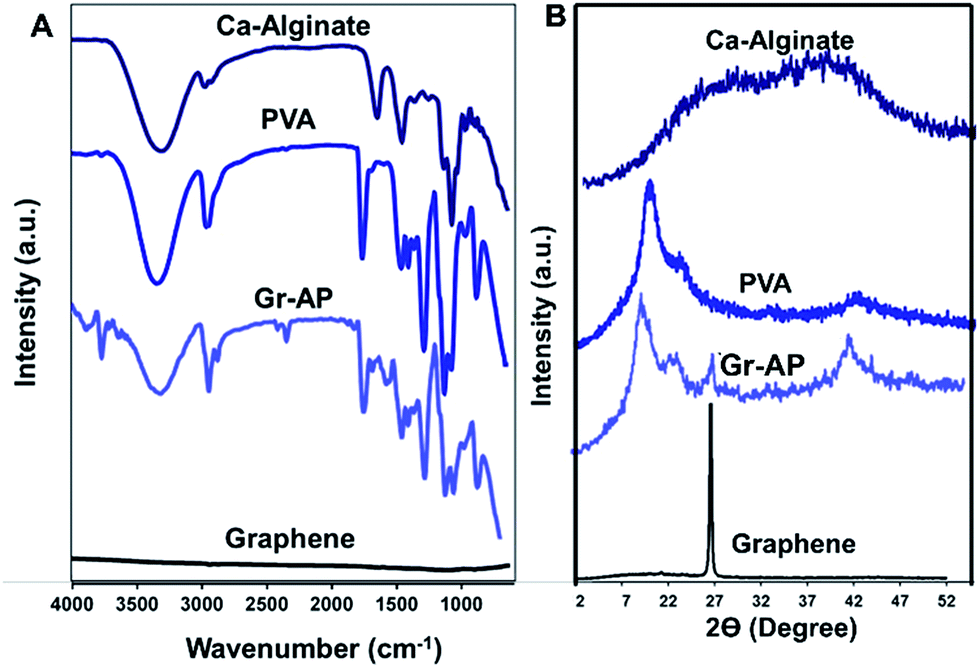 | ||
| Fig. 2 Chemical characterization of Gr-AP scaffolds: (A) FTIR spectra and (B) XRD patterns of Gr-AP scaffolds (after crosslinking process) as well as PVA, alginate and graphene nanosheets. | ||
Analyzing the XRD patterns of fibrous scaffolds after the crosslinking process (Fig. 2B) revealed that Gr-AP scaffolds only consisted of two diffraction peaks at 2Θ = 19.6° and 26.6°. The first peak at 2Θ = 19.6° was related to the homogenous mixing of PVA and alginate within the fibers and the second was graphene nanosheet's characteristic peak according to other researches.49,50 According to XRD patterns of pure PVA and alginate, both were semicrystalline with a broad peak at 2Θ = 19.3° and 26.6°, respectively. After mixing, both peaks disappeared and only one peak at 2Θ = 19.6° could be detected which could be due to their homogeneous blending and the interactions between them. This behavior was similarly reported in previous studies.46,48
The tensile properties of the aligned and random fibrous scaffolds were measured at room temperature to determine their strength, elastic modulus and toughness (Fig. 3A and B). The two types of scaffolds exhibited similar stress–strain trends; a linear region followed by plastic deformation without necking. As shown in Fig. 3A, the aligned fibrous scaffolds had improved mechanical strength and less flexibility compared to the randomly oriented fibrous scaffolds. The mechanical strength and elongation of A:Gr-AP versus R:Gr-AP scaffolds were 29.6 ± 6.7 MPa and 72.1 ± 24.8%, and 22.0 ± 1.7 MPa and 116.3 ± 25.7%, respectively, confirming the effective role of the scaffold architecture and fiber orientations on the scaffold's mechanical properties, especially toughness. Elastic modulus (based on the initial 4% strain) and toughness of scaffolds were derived from the stress–strain curves (Fig. 3C and D). Based on our results, A:Gr-AP scaffolds had a higher elastic modulus (1.5 times) and toughness (1.7 times) compared to R:Gr-AP which was due to the orientation of fibers along the direction of the tensile load. During tensile loading, only the fibers oriented along the loading direction experienced the stretching force.51 These results were similarly reported in previous studies as well.14,52,53 For instance, English et al.54 fabricated polyglycolic acid fibrous scaffolds for corneal tissue engineering where they showed that aligned, orientated electrospun fibers exhibited considerably higher stress at break values than their random counterparts (1.5 times), while randomly orientated electrospun fibers exhibited significantly higher strain at break values than the aligned orientated scaffold (2.5 times). In another study by Cooper et al.,55 a blend of chitosan-polycaprolactone (PCL) nanofibrous scaffolds with unidirectional fibers was developed using electrospinning for skeletal muscle tissue reconstruction. Results showed that the tensile modulus and strength of the aligned nanofibrous scaffolds (51.54 MPa and 13.21 MPa, respectively) were significantly greater than those of in randomly oriented nanofibrous scaffolds (8.85 and 3.53 MPa, respectively).55
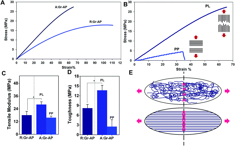 | ||
| Fig. 3 Mechanical properties Gr-AP scaffolds at two different architectures of aligned and random fibers: (A) representative stress–strain curves of aligned and random fibrous Gr-AP scaffolds. (B) Representative stress–strain curves of aligned fibrous Gr-AP scaffolds in two different directions: in parallel (PL) and perpendicular (PP) to the aligned oriented fibers. The average (C) tensile modulus and (D) toughness of the fibrous scaffolds (*P < 0.01) were measured and depicted for comparison. (E) The schematic illustration of aligned and random fibrous scaffolds during the stretching of the contact point of fibers. | ||
To demonstrate the anisotropic mechanical properties of A:Gr-AP scaffolds, mechanical properties were tested in two directions, parallel (PL) and perpendicular (PP). The stress–strain curves of the A:Gr-AP scaffolds in two different orientations, PL and PP, revealed considerably different mechanical properties confirming the anisotropic structure of A:Gr-AP scaffolds (Fig. 3B). Aligned fibrous scaffold in the PP direction had less tensile modulus (9.6 ± 0.7 MPa) and toughness (2.5 ± 1.5 MPa) compared to the PL direction (Fig. 3C and D), which was due to the weak interaction of adjacent fibers. The lack of physical and chemical bonding between the fibers (perpendicular to their orientation) resulted in more flexibility and weaker scaffolds in PP direction. These results were consistent with previous studies where aligned silk fibroin fibrous scaffolds were developed for peripheral nerve regeneration. The scaffolds exhibited strong tensile strength of approximately 12.3 MPa in the aligned direction, compared to 3.5 MPa in the other direction.56 Previously, we reported that random fibrous PCL:PGS (1:4) had lower mechanical properties than aligned one where the tensile modulus and strength of aligned scaffolds were approximately 10 and 4 MPa, respectively, while the random scaffolds were approximately 7 and 1.5 MPa, respectively. Furthermore, the mechanical properties of aligned scaffolds revealed physically relevant anisotropy.57 The mechanical properties of the scaffolds provided the necessary support for in vivo suturing and cell and tissue function following implantation.58 Our results confirmed that A:Gr-AP scaffolds showed significant toughness as well, suitable for nerve tissue engineering.
To evaluate the ability of A:Gr-AP scaffolds for neural growth, PC12 cells were seeded on the scaffolds. The effects of scaffold architecture and mechanical properties on cell attachment, orientation and proliferation were assessed. The PC12 cell orientation was measured on tissue culture plastic (TCP) as well as aligned and random fibrous scaffolds after 1, 4 and 7 days of culture (Fig. 4). The orientation of cell nuclei was measured using Image J software. Over the 7 day period, no preferred cell nuclei orientation was observed on the R:Gr-AP scaffold and TCP as PC12 cells grew in random directions. On the contrary, after 4 days of culture on the aligned fibrous scaffold, PC12 cells were preferentially oriented at 0–20 degree (35%). Calculations confirmed that at day 7, while 56% of cells cultured on aligned scaffold were oriented at 0–20 degree, only 23.1% and 22.7% of PC12 cells were oriented on the random fibrous scaffold and TCP, respectively (Fig. 5A). According to these results, the aligned fibrous scaffolds promoted aligned organization of PC12 cells, by controlling the orientation of neurons by a mechanism previously termed contact guidance.10,36
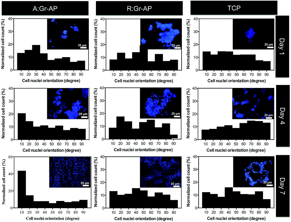 | ||
| Fig. 4 Fluorescence images of the PC12 cell nuclei and the distribution of cell nuclei alignment angles on A:Gr-AP, R:Gr-AP scaffolds as well as TCP (control) after 1, 4 and 7 days of culture (scale bar 25 μm). | ||
 | ||
| Fig. 5 (A) Percentage of cells with orientation angles within 0–20 degrees. (B) Proliferation of the PC12 cells on the aligned and random fibrous scaffolds as well as TCP (*P < 0.01). SEM images of PC12 cells cultured on (C) random and (D) aligned fibrous Gr-AP scaffolds. (E) Illustration of PC12 outgrowth and orientation on the aligned fibrous scaffolds. Distribution of Gr nanosheets resulted in the formation of a conductive path within the fibrous scaffolds. | ||
PC12 cell attachment and proliferation were also analyzed by DAPI staining of nuclei and cell counting after 1, 4 and 7 days of culture (Fig. 5B). After one day of culture, the attachment of PC12 cells on the aligned fibrous scaffolds was significantly greater than in random fibrous scaffolds which might be due to the difference in chemical properties of the constructs such as hydrophilicity which the attachment of cells to the substrates is mandatory for cell regeneration (ESI Fig. S3†). The proliferation of PC12 cells on the aligned fibrous scaffolds was also significantly higher compared to the random fibrous scaffolds and TCP (P < 0.05). For instance, after 7 days, 6.3-fold and 2.4-fold more PC12 cells were counted on the aligned scaffolds (669.1 ± 92.9 cells) than the TCP (105.4 ± 4.9 cells) and random scaffolds (281.3 ± 52.8 cells) (P < 0.05), respectively. Previous studies also demonstrated that the number of Schwan cells seeded on aligned PCL-gelatin fibers was greater than that of random fibers.36 The effect of scaffold topography on cells–substrate interactions confirmed that aligned architecture, similar to the native structure, could enhance cell attachment and cell proliferation.
SEM images of PC12 cells cultured for 7 days on R:Gr-AP and A:Gr-AP scaffolds were obtained (Fig. 5C and D). The random fibrous scaffold (Fig. 5C) resulted in spreading of cells without any specific orientation. In contrast, on the aligned fibrous scaffolds (Fig. 5D), the cells oriented along the direction of the fibers and clustered around the aligned fibers in a longitudinal fashion. Similar results were reported when PC12 cells were seeded on aligned and random fibrous PCL/gelatin scaffolds indicating the remarkable potential of an aligned fibrous scaffold to guide PC12 cell orientation parallel to the direction of uniaxial fibers.59,60 Moreover, fiber size can have a significant impact on cell adhesion and proliferation. This could be due to the fact that the aligned fibrous membrane provides smaller fibers that the cells are more easily able to grab and spread on resulting in more growth of PC12 cells.61 In addition to fiber size and orientation, the alignment of PC12 cells might be related to the distribution of graphene nanosheets within the hybrid scaffolds. Graphene nanosheets can create an electrical network through the polymeric fibers inducing electrical conductance, by percolation theory.62 The existence of graphene nanosheets provides a conductive path and potential direction for axonal growth. The positive effects of topographical and electrical cues on neural development has further been shown in other studies.63,64 Subramanian et al.65 demonstrated that electrically conducting nanofibers provide both electrical and structural cues to neurons. Poly(lactide-co-glycolide) (PLGA) with poly(3-hexylthiophene) (PHT) were electrospun in two different architectures of random and aligned fibers. Results showed that aligned PLGA–PHT nanofibers had a significant influence on the adhesion and proliferation of Schwann cells which extended along the fiber direction and conductive path on aligned scaffolds.
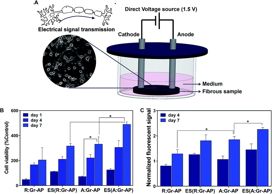
Previous researches demonstrated that electrical stimulation (ES) could alter the cell growth and proliferation by guiding remodeling of the cellular microenvironment as well as adjusting gene expression.66,67 Therefore, the proliferation of PC12 cells was also assessed after applying electrical stimulation on A:Gr-AP and R:Gr-AP scaffolds. Previous studies have shown that electrical field plays a more substantial role than electrical current in modulating the activity of cells cultured on conductive scaffolds.67–70 In this study, we applied an electrical field as a physical adjunct, in order to enhance the speed and accuracy of neuron outgrowth.71,72 Fig. 6A illustrates the procedure for electrical stimulation (ES) and the extension of neuronal outgrowth schematically. The metabolic activity and proliferation of PC12 cells on A:Gr-AP, R:Gr-AP and TCP were assessed by MTT assay after 1, 4 and 7 days of culture, with and without ES (Fig. 6B and C). The proliferation of PC12 cells on A:Gr-AP scaffolds after electrical stimulation enhanced significantly from day 1 (125.7 ± 11.1 (% control)) to day 7 (489.8 ± 20.7 (% control)). The PC12 proliferation on A:Gr-AP scaffold after electrical stimulation (ES(A:Gr-AP)) was notably greater than without ES (p < 0.05). Though ES also increased proliferation on random fiber scaffolds, after 7 days of culture, proliferation on ES(A:Gr-AP) scaffolds was 1.5 times greater than that of ES(R:Gr-AP). These results were in agreement with another study, where direct electrical stimulation (constant voltage; 1.5 V) was shown to enhance neural cell proliferation.28 Extracellular electric field could directly act on the neural cell by changing membrane potential asymmetrically and therefore preferentially activate growth-controlling transport processes across the plasma membrane. It could also act along the plasma membrane, causing an electrophoretic accumulation of the surface molecules responsible for neurite growth control or cell-substratum adhesion.73
 | ||
| Fig. 6 (A) Schematic representation of electrical stimulation. (B) MTT and (C) resazurin assays of PC12 cells cultured on the aligned and random fibrous Gr-AP scaffolds before and after electrical stimulation (*P < 0.05). | ||
The proliferation of PC12 cells on Gr-AP scaffolds was also evaluated by resazurin assay (Fig. 6C). This assay confirmed that the proliferation of cells increased on various scaffolds with increasing culture time (P < 0.05). Moreover, PC12 cells on A:Gr-AP scaffolds had higher proliferation rates than those on R:Gr-AP. After 7 days of cell culture, the fluorescent resazurin measurement for R:Gr-AP and A:Gr-AP scaffolds were 1.28 and 1.84, respectively. Furthemore, ES improved cell proliferation even further.
4. Conclusion
In summary, two critical stimuli required to enhance peripheral nerve regeneration in vivo, electrical conductance and anisotropic architecture, were developed in graphene nanosheets embedded aligned fibrous PVA-alginate (A:Gr-AP) scaffolds to create highly functionalized nerve scaffolds that could control alignment and proliferation of neurons. The alignment of fibers with the orientation index of 28.7° matched the anisotropic structure of native nerve fibers (26.8°). The fiber alignment also improved the mechanical properties of Gr-AP scaffolds. Remarkably, the toughness of A:Gr-AP scaffolds was 1.75 times greater than that of R:Gr-AP. The architecture and anisotropic mechanical properties of aligned hybrid Gr-AP scaffolds provided an appropriate microenvironment to support PC12 cell attachment and proliferation. The alignment of PC12 cells was influenced by the architecture of the scaffolds and enhanced with increasing culture time on the aligned fibrous scaffold. Contrary to the R:Gr-AP scaffolds, the alignment of fibers in the A:Gr-AP scaffold induced PC12 attachment and growth in the longitudinal axis parallel to the direction of the fibers. PC12 cell proliferation was also significantly influenced by the scaffold architecture and electrical stimulation (ES). We were able to show that ES considerably improved the proliferation of cells (1.5 times) cultured on A:Gr-AP scaffolds. In conclusion, the aligned and conductive Gr-AP fibrous scaffolds, with optimum mechanics and architecture, are potentially an improved substrate for nerve tissue regeneration.Conflicts of interest
There are no conflicts to declare.References
- J. Xie, M. R. MacEwan, A. G. Schwartz and Y. Xia, Nanoscale, 2010, 2, 35–44 RSC.
- F. Fregnan, M. Morano, O. Ziv-Polat, M. M. Mandelbaum-Livnat, M. Nissan, T. Michael, A. Koren, T. Biran, Y. Bitan and E. Reider, in Peripheral Nerve Regeneration-From Surgery to New Therapeutic Approaches Including Biomaterials and Cell-Based Therapies Development, InTech, 2017 Search PubMed.
- B. Dhandayuthapani, Y. Yoshida, T. Maekawa and D. S. Kumar, Int. J. Polym. Sci., 2011, 2011, 1–19 CrossRef.
- R. Lanza, R. Langer and J. P. Vacanti, Principles of tissue engineering, Academic press, 2011 Search PubMed.
- R. A. Weber, W. C. Breidenbach, R. E. Brown, M. E. Jabaley and D. P. Mass, Plast. Reconstr. Surg., 2000, 106, 1036–1045 CAS.
- J. S. Taras, V. Nanavati and P. Steelman, J. Hand Ther., 2005, 18, 191–197 CrossRef PubMed.
- W. W. Ashley Jr, T. Weatherly and T. S. Park, J. Neurosurg. Pediatr., 2006, 105, 452–456 CrossRef PubMed.
- F. Mottaghitalab, M. Farokhi, A. Zaminy, M. Kokabi, M. Soleimani, F. Mirahmadi, M. A. Shokrgozar and M. Sadeghizadeh, PLoS One, 2013, 8(9), e74417 CAS.
- J. Ai, A. Kiasat-Dolatabadi, S. Ebrahimi-Barough, A. Ai, N. Lotfibakhshaiesh, A. Norouzi-Javidan, H. Saberi, B. Arjmand and H. R. Aghayan, Arch. Neurol., 2014, 1, 15–20 Search PubMed.
- L. Ghasemi-Mobarakeh, M. P. Prabhakaran, M. Morshed, M. H. Nasr-Esfahani and S. Ramakrishna, Biomaterials, 2008, 29, 4532–4539 CrossRef CAS PubMed.
- J. Xie, M. R. MacEwan, W. Liu, N. Jesuraj, X. Li, D. Hunter and Y. Xia, ACS Appl. Mater. Interfaces, 2014, 6, 9472–9480 CAS.
- Y. Zou, J. Qin, Z. Huang, G. Yin, X. Pu and D. He, ACS Appl. Mater. Interfaces, 2016, 8, 12576–12582 CAS.
- E. Masaeli, P. A. Wieringa, M. Morshed, M. H. Nasr-Esfahani, S. Sadri, C. A. van Blitterswijk and L. Moroni, Nanomedicine: Nanotechnology, Biology and Medicine, 2014, 10, 1559–1569 CrossRef CAS PubMed.
- D. Gupta, J. Venugopal, M. P. Prabhakaran, V. R. Dev, S. Low, A. T. Choon and S. Ramakrishna, Acta Biomater., 2009, 5, 2560–2569 CrossRef CAS PubMed.
- M. P. Prabhakaran, L. GhasemiMobarakeh, G. Jin and S. Ramakrishna, J. Biosci. Bioeng., 2011, 112, 501–507 CrossRef CAS PubMed.
- N. Gomez and C. E. Schmidt, J. Biomed. Mater. Res., Part A, 2007, 81, 135–149 CrossRef PubMed.
- K. Tonsomboon and M. L. Oyen, J. Mech. Behav. Biomed. Mater., 2013, 21, 185–194 CrossRef CAS PubMed.
- D. Zhang and J. Chang, Nano Lett., 2008, 8, 3283–3287 CrossRef CAS PubMed.
- K. Zhang, H. Zheng, S. Liang and C. Gao, Acta Biomater., 2016, 37, 131–142 CrossRef CAS PubMed.
- S. Ryu and B.-S. Kim, Tissue Eng. Regener. Med., 2013, 10, 39–46 CrossRef CAS.
- J. Huang, H. Deng, D. Song and H. Xu, Anal. Chim. Acta, 2015, 878, 102–108 CrossRef CAS PubMed.
- G. Reina, J. M. González-Domínguez, A. Criado, E. Vázquez, A. Bianco and M. Prato, Chem. Soc. Rev., 2017, 46, 4400–4416 RSC.
- P. Moroder, M. B. Runge, H. Wang, T. Ruesink, L. Lu, R. J. Spinner, A. J. Windebank and M. J. Yaszemski, Acta Biomater., 2011, 7, 944–953 CrossRef CAS PubMed.
- N. Golafshan, M. Kharaziha and M. Fathi, Carbon, 2017, 111, 752–763 CrossRef CAS.
- G. C. Engelmayr, M. Cheng, C. J. Bettinger, J. T. Borenstein, R. Langer and L. E. Freed, Nat. Mater., 2008, 7, 1003–1010 CrossRef CAS PubMed.
- M. Kharaziha, S. R. Shin, M. Nikkhah, S. N. Topkaya, N. Masoumi, N. Annabi, M. R. Dokmeci and A. Khademhosseini, Biomaterials, 2014, 35, 7346–7354 CrossRef CAS PubMed.
- M. Mejía, M. Salgado-Bustamante, C. G. Castillo and M. E. Jiménez-Capdeville, Toxicol. Res., 2013, 2, 388 RSC.
- L. Ghasemi-Mobarakeh, M. P. Prabhakaran, M. Morshed, M. H. Nasr-Esfahani and S. Ramakrishna, Tissue Eng., Part A, 2009, 15, 3605–3619 CrossRef CAS PubMed.
- J. I. Kim, T. I. Hwang, L. E. Aguilar, C. H. Park and C. S. Kim, Sci. Rep., 2016, 6, 23761 CrossRef CAS PubMed.
- J. Isaacs and T. Browne, Hand, 2014, 9, 131–137 CrossRef PubMed.
- İ. Mutlay and L. B. Tudoran, Fullerenes, Nanotubes, Carbon Nanostruct., 2014, 22, 413–433 CrossRef.
- M. Kharaziha, M. Nikkhah, S. R. Shin, N. Annabi, N. Masoumi, A. K. Gaharwar, G. Camci-Unal and A. Khademhosseini, Biomaterials, 2013, 34, 6355–6366 CrossRef CAS PubMed.
- C.-B. Jenq, L. L. Jenq and R. E. Coggeshall, Exp. Neurol., 1987, 97, 662–671 CrossRef CAS PubMed.
- L. E. Kokai, Y.-C. Lin, N. M. Oyster and K. G. Marra, Acta Biomater., 2009, 5, 2540–2550 CrossRef CAS PubMed.
- A. R. Nectow, K. G. Marra and D. L. Kaplan, Tissue Eng. B Rev., 2012, 18, 40–50 CrossRef CAS PubMed.
- S. Gnavi, B. E. Fornasari, C. Tonda-Turo, R. Laurano, M. Zanetti, G. Ciardelli and S. Geuna, Int. J. Mol. Sci., 2015, 16, 12925–12942 CrossRef CAS PubMed.
- Z. Chen, L. Wang and H. Jiang, Biofabrication, 2012, 4, 035007 CrossRef PubMed.
- H. Chen and Y. L. Hsieh, J. Polym. Sci., Part A: Polym. Chem., 2004, 42, 6331–6339 CrossRef CAS.
- F. Chen, Y. Su, X. Mo, C. He, H. Wang and Y. Ikada, J. Biomater. Sci., Polym. Ed., 2009, 20, 2117–2128 CrossRef CAS PubMed.
- A. J. Fatani, S. S. Al-Rejaie, H. M. Abuohashish, A. Al-Assaf, M. Y. Parmar, M. S. Ola and M. Ahmed, Exp. Ther. Med., 2015, 9, 1670–1678 CrossRef PubMed.
- M. Harrold and R. Zavod, Basic concepts in medicinal chemistry, American Society of Health System, 2013 Search PubMed.
- M. S. Kim and G. Kim, Carbohydr. Polym., 2014, 114, 213–221 CrossRef CAS PubMed.
- O. Sanli, N. Ay and N. Isiklan, Eur. J. Pharm. Biopharm., 2007, 65, 204–214 CrossRef CAS PubMed.
- M. Ottosson, A. Jakobsson and F. Johansson, PLoS One, 2017, 12, e0169419 Search PubMed.
- W. Siriwatcharapiboon, N. Tinnarat and P. Supaphol, J. Polym. Res., 2013, 20, 1–8 CrossRef CAS.
- K. T. Shalumon, K. H. Anulekha, S. V. Nair, S. V. Nair, K. P. Chennazhi and R. Jayakumar, Int. J. Biol. Macromol., 2011, 49, 247–254 CrossRef CAS PubMed.
- S. R. Kim, S. H. Yuk and M. S. Jhon, Eur. Polym. J., 1997, 33, 1009–1014 CrossRef CAS.
- M. S. Islam and M. R. Karim, Colloids Surf., A, 2010, 366, 135–140 CrossRef CAS.
- D. Kumari, L. Sheikh, S. Bhattacharya, T. J. Webster and S. Nayar, Int. J. Nanomed., 2017, 12, 3605 CrossRef PubMed.
- I. R. Kottegoda, N. H. Idris, L. Lu, J.-Z. Wang and H.-K. Liu, Electrochim. Acta, 2011, 56, 5815–5822 CrossRef CAS.
- A. Baji, Y.-W. Mai, S.-C. Wong, M. Abtahi and P. Chen, Compos. Sci. Technol., 2010, 70, 703–718 CrossRef CAS.
- G. G. Genchi, G. Ciofani, A. Polini, I. Liakos, D. Iandolo, A. Athanassiou, D. Pisignano, V. Mattoli and A. Menciassi, J. Tissue Eng. Regener. Med., 2015, 9, 151–161 CrossRef CAS PubMed.
- F. Yang, R. Murugan, S. Wang and S. Ramakrishna, Biomaterials, 2005, 26, 2603–2610 CrossRef CAS PubMed.
- A. English, A. Azeem, D. Gaspar, K. Keane, P. Kumar, M. Keeney, N. Rooney, A. Pandit and D. Zeugolis, J. Mater. Sci.: Mater. Med., 2012, 23, 137–148 CrossRef CAS PubMed.
- A. Cooper, S. Jana, N. Bhattarai and M. Zhang, J. Mater. Chem., 2010, 20, 8904–8911 RSC.
- Q. Liu, J. Huang, H. Shao, L. Song and Y. Zhang, RSC Adv., 2016, 6, 7683–7691 RSC.
- N. Masoumi, B. L. Larson, N. Annabi, M. Kharaziha, B. Zamanian, K. S. Shapero, A. T. Cubberley, G. Camci-Unal, K. Manning and J. E. Mayer, Adv. Healthcare Mater., 2014, 3, 929–939 CrossRef CAS PubMed.
- N. Masoumi, N. Annabi, A. Assmann, B. L. Larson, J. Hjortnaes, N. Alemdar, M. Kharaziha, K. B. Manning, J. E. Mayer and A. Khademhosseini, Biomaterials, 2014, 35, 7774–7785 CrossRef CAS PubMed.
- T. Fee, S. Surianarayanan, C. Downs, Y. Zhou and J. Berry, PloS One, 2016, 11, e0154806 Search PubMed.
- A. Cooper, N. Bhattarai and M. Zhang, Carbohydr. Polym., 2011, 85, 149–156 CrossRef CAS.
- X. Wang, T. Lou, W. Zhao, G. Song, C. Li and G. Cui, J. Biomater. Appl., 2016, 30, 1545–1551 CrossRef CAS PubMed.
- A. V. Kyrylyuk, M. C. Hermant, T. Schilling, B. Klumperman, C. E. Koning and P. van der Schoot, Nat. Nanotechnol., 2011, 6, 364–369 CrossRef CAS PubMed.
- N. Li, Q. Zhang, S. Gao, Q. Song, R. Huang, L. Wang, L. Liu, J. Dai, M. Tang and G. Cheng, Sci. Rep., 2013, 3, 1604 CrossRef PubMed.
- M. Tang, Q. Song, N. Li, Z. Jiang, R. Huang and G. Cheng, Biomaterials, 2013, 34, 6402–6411 CrossRef CAS PubMed.
- A. Subramanian, U. M. Krishnan and S. Sethuraman, J. Mater. Sci.: Mater. Med., 2012, 23, 1797–1809 CrossRef CAS PubMed.
- H. Park, R. Bhalla, R. Saigal, M. Radisic, N. Watson, R. Langer and G. Vunjak-Novakovic, J. Tissue Eng. Regener. Med., 2008, 2, 279–287 CrossRef CAS PubMed.
- A. Kotwal and C. E. Schmidt, Biomaterials, 2001, 22, 1055–1064 CrossRef CAS PubMed.
- R. A. Green, N. H. Lovell, G. G. Wallace and L. A. Poole-Warren, Biomaterials, 2008, 29, 3393–3399 CrossRef CAS PubMed.
- C. E. Schmidt, V. R. Shastri, J. P. Vacanti and R. Langer, Proc. Natl. Acad. Sci. U. S. A., 1997, 94, 8948–8953 CrossRef CAS.
- G. Shi, M. Rouabhia, S. Meng and Z. Zhang, J. Biomed. Mater. Res., Part A, 2008, 84, 1026–1037 CrossRef PubMed.
- Y.-S. Chen, Biomedicine, 2011, 1, 33–36 CrossRef.
- C. Xu, Y. Kou, P. Zhang, N. Han, X. Yin, J. Deng, B. Chen and B. Jiang, PloS One, 2014, 9, e105045 Search PubMed.
- N. Patel and M.M. Poo, J. Neurosci., 1982, 2, 483–496 CAS.
Footnote |
| † Electronic supplementary information (ESI) available. See DOI: 10.1039/c7ra13136d |
| This journal is © The Royal Society of Chemistry 2018 |