 Open Access Article
High voltage, solvent-free solid polymer electrolyte based on a star-comb PDLLA–PEG copolymer for lithium ion batteries†
Bingbing Wangab,
Hongming Lou a,
Hongli Xub,
Junpeng Zhao
 c,
Qiujun Wangd,
Qiao Shid and
Yonghong Deng
 *b
*b
aSchool of Chemistry and Chemical Engineering, South China University of Technology, Guangzhou, 516640, China. E-mail: cehmlou@scut.com
bDepartment of Materials Science and Engineering, South University of Science and Technology of China, Shenzhen, 518055, China. E-mail: dengyh@sustc.edu.cn; yhdeng08@163.com
cResearch Institute of Materials Science, South China University of Technology Guangzhou, 510640, China
dShenzhen Capchem Technology Co., LTD, Shenzhen, 518118, China
First published on 8th February 2018
Abstract
In this work, a novel star-comb copolymer based on poly(d,L-lactide) (PDLLA) macromonomer and poly(ethylene glycol)methyl ether methacrylate (PEGMA) was prepared, and the electrochemical properties were studied, with the aim of using it as a solid polymer electrolyte in lithium ion batteries. The six-arm vinyl functionalized PDLLA macromonomer was synthesized by a ring-opening polymerization (ROP) of D,L-lactide and subsequently an acylation of the hydroxy end-groups. A series of free-standing solid polymer electrolyte membranes from different ratios of PDLLA, PEGMA and LiTFSI were prepared through solvent-free free radical polymerization under UV radiation. The chemical structure of the obtained polymers was confirmed by 1H NMR and FTIR. The as-prepared six-arm star-comb solid polymer electrolytes (PDLLA-SPEs) exhibit good thermal stability with Td5%s of ∼270 °C and low Tgs of −48 to −34 °C. The electrochemical characterization shows that the PDLLA-SPEs possess a wide electrochemical window up to 5.1 V with an optimal ionic conductivity of 9.7 × 10⁻⁵ S cm−1 at 60 °C at an EO/Li+ ratio of 16![[thin space (1/6-em)]](https://www.rsc.org/images/entities/char_2009.gif) :
:![[thin space (1/6-em)]](https://www.rsc.org/images/entities/char_2009.gif) 1. Furthermore, the all-solid-state LiFePO4/Li cells display extraordinary cycling and rate performances at 60 °C by curing the PDLLA-SPEs directly on the cathode. These superior properties of the six-arm star-comb PDLLA-SPE make it a promising candidate solid electrolyte for lithium batteries.
1. Furthermore, the all-solid-state LiFePO4/Li cells display extraordinary cycling and rate performances at 60 °C by curing the PDLLA-SPEs directly on the cathode. These superior properties of the six-arm star-comb PDLLA-SPE make it a promising candidate solid electrolyte for lithium batteries.
Introduction
Lithium secondary batteries have been widely applied in portable and consumable electronic devices such as cell phones and computers because of their high energy density, long lifespan, lack of memory effects, etc.1,2 However, the development of lithium batteries is restricted by safety risks caused by the use of conventional organic liquid electrolytes, which are highly flammable and explosive.3 To solve this, solid polymer electrolytes (SPEs) have been developed due to their easier processability, lighter weight, higher energy density and safety.Poly(ethylene oxide) (PEO) is one of the most widely studied solid electrolyte matrices. However, due to its high degree of crystallinity at room temperature, the migration of Li+ is hindered. As a result, the ionic conductivity of PEO-based solid electrolytes only reaches an order of magnitude of 10−7 S cm−1 at ambient temperature.4 Besides, the electrochemical stability window of PEO is lower than 4 V, restricting the selection of cathode materials.5 Various strategies have been carried out to improve electrochemical properties of PEO, such as blending,6 copolymerization,7 and crosslinking.8 Among these approaches, preparing copolymers, especially graft copolymers, can decrease the crystallinity of a PEO-based solid electrolyte system effectively. As a result, the ionic conductivities are improved and also the mechanical properties of SPEs are enhanced in some cases. Ding et al. reported the synthesis of amorphous comb-like SPEs from methyl vinyl ether/maleic anhydride copolymer with oligo(oxyethylene) side chains, which shows a maximum conductivity of 4.9 × 10⁻⁵ S cm−1 at 25 °C.9 Daigle et al. reported a set of SPEs based on comb-like copolymers originated from styrene (St), 4-vinylanisole (VA) and PEGMA, which shows good conductivity (6.8 × 10⁻⁵ S cm−1) at room temperature.10 What's more, preparing multi-arm star-shaped copolymer with both rigid core and flexible segment is another effective way to suppress crystallinity of SPE matrix, as well as to improve mechanical properties.11–13 According to the pioneering work, star-shaped copolymers based SPEs usually show improved ambient conductivities (∼10−5 S cm−1).11–15 As a bonus, the mechanical performance of the SPE films can be improved significantly by introducing the rigid component.12
Another widely studied polymer matrix for SPE is polyester, which has wide electrochemical window and high permittivity. Brandell's group reported a flexible poly(trimethylene carbonate) (PTMC)-based SPE with LiTFSI, of which the electrochemical window is up to 5.0 V (vs. Li/Li+) and the ionic conductivity is in an order of 10−7 S cm−1 at 60 °C.16 Chai et al. fabricated a poly(vinylene carbonate) (PVC) based SPE by in situ polymerization, the electrochemical stability window and the ionic conductivity can reach 4.5 V (vs. Li/Li+) and 9.8 × 10⁻⁵ S cm−1 at 50 °C, respectively.17 Due to its high modulus and low elongation,18,19 using polylactide as an electrolyte matrix was seldom reported. Chew et al. first prepared a polylactide-based gel polymer electrolyte (GPE) with lithium perchloride (LiClO4) as a salt, ethylene carbonate (EC) as a plasticizer and silicon dioxide ceramic (SiO2) as a filler by typical solution casting technique, but the ambient ionic conductivity is only 1.29 × 10⁻⁵ S cm−1 without any extra electrochemical properties reported.20 Tan et al. developed a SPE from polylactide–poly(ethylene glycol) (PDLLA–PEG) block copolymer with lithium iodide as a salt, which achieved an optimum ionic conductivity of 4.17 × 10⁻⁶ S cm−1 at room temperature.21 PDLLA was selected in his work, rather than PLLA or PDLA, was due to the highly amorphous nature of PDLLA, which favors Li+ ionic transportation.22
In this work, a six-arm poly(d,L-lactide) (PDLLA) macromonomer that end-capped with vinyl functionalities was prepared via a ring-opening polymerization (ROP) of D,L-lactide and an acylation of the hydroxy end-groups. A series of novel free-standing star-comb PDLLA-based solid polymer electrolytes (hereafter abbreviated as “PDLLA-SPE”) with six-arm PDLLA as core, poly(ethylene glycol)methyl ether methacrylate (PEGMA) as side chains and LiTFSI as conducting salt were prepared through free radical polymerization under UV radiation. To the best of our knowledge, this is the first example of design and use a star comb-like block copolymer from a multi-arm PDLLA with branching PEG side chains as SPE for lithium ion batteries. The multi-arm PDLLA is anticipated to provide with high electrochemical stability and good mechanical properties, and the PEG side chains enable the block copolymers with a promising ionic conductivity. The structure of the obtained polymer was characterized by 1H NMR and FTIR. The thermal and electrochemical properties of these electrolytes were systematically investigated. The results showed that PDLLA-SPEs exhibit good thermal stability and possess a wide electrochemical window and a relatively high ionic conductivity. Furthermore, the all-solid-state LiFePO4/Li cell displayed extraordinary cycling and rate performances at 60 °C by integrating cathode with PDLLA-SPE. The as-developed PDLLA-SPE is attractive for using as solid electrolyte in lithium ion batteries with enhanced ionic conductivity and long-term durability.
Experimental
Materials
d,L-Lactide (DLLA, 99.0%, J&K), methacryloyl chloride (97.0%, Aldrich), triethylamine (>99.5%, Aladdin), methanol (≥99.5%, Aladdin), inositol (99.0%, Macklin), 4-dimethylaminopyridine (DMAP, 99.0%, Macklin), Irgacure 1173 (photoinitiator, BASF), PEGMA (Mn = 500 g mol−1, Sigma-Aldrich) and PEO (Mn = 600![[thin space (1/6-em)]](https://www.rsc.org/images/entities/char_2009.gif) 000 g mol−1, Sigma-Aldrich) were used as received without further purification, unless stated otherwise. Dichloromethane (CH2Cl2, ≥99.5%, Aladdin) and acetonitrile (ACN, ≥99.5%, Aladdin) were dried with CaH2 and distilled under reduced pressure prior to use. Lithium bis(trifluoromethanesulfonyl)-imide (LiTFSI, 99%, Shenzhen Capchem Technology Co., Ltd.) was dried under vacuum at 80 °C for 24 h before use. LiFePO4 (LFP), Super P and other battery accessories were purchased from Shenzhen Kejing.
000 g mol−1, Sigma-Aldrich) were used as received without further purification, unless stated otherwise. Dichloromethane (CH2Cl2, ≥99.5%, Aladdin) and acetonitrile (ACN, ≥99.5%, Aladdin) were dried with CaH2 and distilled under reduced pressure prior to use. Lithium bis(trifluoromethanesulfonyl)-imide (LiTFSI, 99%, Shenzhen Capchem Technology Co., Ltd.) was dried under vacuum at 80 °C for 24 h before use. LiFePO4 (LFP), Super P and other battery accessories were purchased from Shenzhen Kejing.
Synthesis of six-arm star PDLLA macromonomer
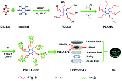
PDLLA was synthesized by ring-opening polymerization (ROP) of D,L-lactide (DLLA) according to literature.23 Typically, the bulk polymerization of DLLA was conducted at 160 °C, using inositol as the initiator and DMAP as the organo-catalyst under a nitrogen atmosphere. Subsequently, methacryloyl chloride was utilized to prepare the vinyl-functionalized PDLLA. The as-prepared vinyl end-functionalized PDLLA macromonomer was hereafter labeled as PLAHA (as shown in Fig. 1).Preparation of PDLLA-SPE and PEO-SPE membranes
The fabrication of PDLLA-SPE and PEO-SPE membranes were conducted as follows and all operations were carried out in a glove box under an argon atmosphere (H2O <1 ppm).PDLLA-SPE membranes were fabricated via a facile in situ solvent-free radical polymerization method (shown in Fig. 1). The as-prepared polymer PLAHA and lithium salt (LiTFSI) were added to PEGMA in sequence under intense stirring to form a homogeneous solution. The weight ratio of PLAHA to PEGMA was set to 1![[thin space (1/6-em)]](https://www.rsc.org/images/entities/char_2009.gif) :
:![[thin space (1/6-em)]](https://www.rsc.org/images/entities/char_2009.gif) 4 in order to obtain a solution with proper viscosity. The concentration of LiTFSI was controlled by varying EO/Li+ molar ratios from 8 to 24. Then the photoinitiator (1 wt% to the monomer mixtures) was added to the solution, followed by pouring the homogeneous solution onto different substrates of stainless steels, Li metal anodes or cathode layers, depending on the different characterization requirements. The PDLLA-SPE membranes were obtained by in situ radical polymerization under UV irradiation for 20 minutes. Finally, the prepared PDLLA-SPE membranes were dried under vacuum at 60 °C for 48 h prior to use. The average thickness of the membranes is approximately 500 μm. To confirm the cross-linking density, PDLLA–PEG copolymer was immersed in dichloromethane for 3 days. Subsequently, the undissolved solid was dried under vacuum at 60 °C for 24 h. The cross-linking density is about 95%, as calculated by the weight ratio of the sample before and after immersion.
4 in order to obtain a solution with proper viscosity. The concentration of LiTFSI was controlled by varying EO/Li+ molar ratios from 8 to 24. Then the photoinitiator (1 wt% to the monomer mixtures) was added to the solution, followed by pouring the homogeneous solution onto different substrates of stainless steels, Li metal anodes or cathode layers, depending on the different characterization requirements. The PDLLA-SPE membranes were obtained by in situ radical polymerization under UV irradiation for 20 minutes. Finally, the prepared PDLLA-SPE membranes were dried under vacuum at 60 °C for 48 h prior to use. The average thickness of the membranes is approximately 500 μm. To confirm the cross-linking density, PDLLA–PEG copolymer was immersed in dichloromethane for 3 days. Subsequently, the undissolved solid was dried under vacuum at 60 °C for 24 h. The cross-linking density is about 95%, as calculated by the weight ratio of the sample before and after immersion.
PEO-SPE membranes were prepared by conventional solution-casting technique.24 PEO and LiTFSI were dissolved in acetonitrile with EO/Li+ = 16. A homogeneous solution was obtained after intense stirring, which was casted into a Teflon plate and the solvent was allowed to evaporate slowly for 24 h in a desiccator. Finally, the prepared PEO-SPE membranes were dried under vacuum at 60 °C for 48 h and then punched into circles with diameters of 17 mm for further measurements. The average thickness of the membranes was measured to be ∼500 μm.
Assembly of all-solid-state cells
The LFP cathode was prepared by automobile doctor blade from a mixture composted of 70 wt% LFP, 20 wt% SPE as a binder and 10 wt% Super-P in acetonitrile. The SPE used here was prepared by dissolving a lithium salt (LiClO4) in the as-prepared block copolymer at an EO/Li+ ratio of 16![[thin space (1/6-em)]](https://www.rsc.org/images/entities/char_2009.gif) :
:![[thin space (1/6-em)]](https://www.rsc.org/images/entities/char_2009.gif) 1. LiClO4 was used instead of LiTFSI, is due to its much lower hydroscopicity. CR-2025 coin cells with the LFP/SPE/Li were assembled for further test.
1. LiClO4 was used instead of LiTFSI, is due to its much lower hydroscopicity. CR-2025 coin cells with the LFP/SPE/Li were assembled for further test.
Characterization and measurements
The thermal property of the as-prepared PDLLA-SPEs was characterized by differential scanning calorimetry (DSC) and thermogravimetric analysis (TGA). DSC was performed using a Mettler-Toledo differential scanning calorimetry at temperatures ranging from −60 to 100 °C with a heating/cooling rate of 10 °C min−1 under a nitrogen atmosphere. TGA was carried out on a Mettler-Toledo thermogravimetric analyzer from 30 to 600 °C with a heating rate of 10 °C min−1 under a nitrogen atmosphere. The crystallization behavior was examined by a Bruker Eco D8 X-ray diffractometer (XRD). The degree of crystallinity (%) was calculated from the ratio of the integrated intensity of the crystal peaks to the total integrated intensity.
 | (1) |
Results and discussion
Structure of six-arm star PDLLA macromonomer
The synthesis of PDLLA macromonomer (PLAHA) that end-capped with –C![[double bond, length as m-dash]](https://www.rsc.org/images/entities/char_e001.gif) C– double bonds follows two steps: the preparation of hydroxyl-terminated PDLLA by ring-opening polymerization (ROP) of DLLA and acylation of the terminal hydroxyl functionalities.
C– double bonds follows two steps: the preparation of hydroxyl-terminated PDLLA by ring-opening polymerization (ROP) of DLLA and acylation of the terminal hydroxyl functionalities.
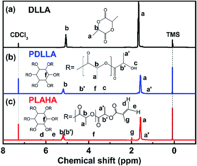
To demonstrate the successful synthesis of PLAHA, the 1H NMR spectras of DLLA, PDLLA and PLAHA are shown in Fig. 2. The resonance a (chemical shift δ = 1.45–1.55 ppm) and b (δ = 5.10–5.35 ppm) are assigned to the proton of –CH3 and –CH at the PDLLA backbone, respectively. The resonance a′ (δ = 1.30–1.35 ppm) and b′ (δ = 4.35–4.39 ppm) are assigned to the proton of –CH3 and –CH at the chain end of the PDLLA backbone.23,25,26 The appearance of the peak c at 3.35–3.40 ppm (terminal –OH of PDLLA) and peak f at 3.75–4.80 ppm (the characteristic –CH– of the six-membered ring of inositol) in NMR spectrum of PDLLA confirms the inositol-initiated ring-opening polymerization of DLLA. Comparing the 1H NMR spectrum of PLAHA with that of PDLLA, the characteristic resonance of –OH at 3.35–3.40 ppm decreased dramatically, together with the arising of the new peaks d and e assigned to the protons on the –C![[double bond, length as m-dash]](https://www.rsc.org/images/entities/char_e001.gif) C– double bond, clearly prove that –C
C– double bond, clearly prove that –C![[double bond, length as m-dash]](https://www.rsc.org/images/entities/char_e001.gif) C– was successfully induced into PDLLA by acylation reaction.
C– was successfully induced into PDLLA by acylation reaction.
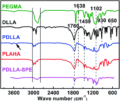
To further confirm the structure of the synthesized polymers, the FTIR spectra of PEGMA, DLLA, PDLLA, PLAHA and PDLLA-SPE are shown in Fig. 3. Characteristic absorption peaks at 3038–2793 cm−1 and 1459 cm−1 that attributed to the stretching vibration and bending vibration of CH3 and CH, respectively, are observed in all of the spectra, as reported previously.27 The strong peaks at 1760 cm−1 are attributed to the stretching vibration of C![[double bond, length as m-dash]](https://www.rsc.org/images/entities/char_e001.gif) O. The symmetrical and antisymmetric stretching vibration peaks of C–O locate at 1102 and 1260 cm−1, respectively. Comparing the spectrum of DLLA with that of PDLLA, a new characteristic peak shows up at 3500 cm−1 of the stretching vibration of terminal hydroxyl O–H in PDLLA. The ring skeleton vibration peaks of DLLA at 960 and 650 cm−1 (ref. 28) decrease dramatically. From the analysis of FTIR spectra, one can conclude that PDLLA was synthesized successfully via ring-opening polymerization of DLLA. After acylation, the corresponding characteristic peak of –OH from PDLLA decrease dramatically and the characteristic vibration of –C
O. The symmetrical and antisymmetric stretching vibration peaks of C–O locate at 1102 and 1260 cm−1, respectively. Comparing the spectrum of DLLA with that of PDLLA, a new characteristic peak shows up at 3500 cm−1 of the stretching vibration of terminal hydroxyl O–H in PDLLA. The ring skeleton vibration peaks of DLLA at 960 and 650 cm−1 (ref. 28) decrease dramatically. From the analysis of FTIR spectra, one can conclude that PDLLA was synthesized successfully via ring-opening polymerization of DLLA. After acylation, the corresponding characteristic peak of –OH from PDLLA decrease dramatically and the characteristic vibration of –C![[double bond, length as m-dash]](https://www.rsc.org/images/entities/char_e001.gif) C– stretching emerges at 1638 cm−1 for PLAHA, indicating that the –C
C– stretching emerges at 1638 cm−1 for PLAHA, indicating that the –C![[double bond, length as m-dash]](https://www.rsc.org/images/entities/char_e001.gif) C– terminated PLAHA was successfully synthesized. The FTIR results are in consistent with the 1H NMR results and all these results clearly confirm the successful synthesis of the PLAHA polymer.
C– terminated PLAHA was successfully synthesized. The FTIR results are in consistent with the 1H NMR results and all these results clearly confirm the successful synthesis of the PLAHA polymer.
Morphology of PDLLA-SPE membranes
The macro and micro morphologies of PDLLA-SPE membranes are shown in Fig. 4. The PDLLA-SPE membrane is a uniform, transparent, self-standing film with good flexibility, as shown in Fig. 4a. The thickness is approximately 500 μm, and can be adjusted by tuning the dosage of precursor solution. The tensile strength is about 109 kPa as detected by tensile experiment as shown in Fig. S1.† The SEM analysis indicates that the surface of PDLLA-SPE membrane is smooth and homogenous, without any visible porous or crystal structure (Fig. 4b). As a sharp contrast, the SEM image clearly shows a typical semi-crystalline phase and porous morphology at the surface of PEO-SPE membrane, as shown in Fig. 4c. This is highly in agreement with literature.29,30 The much smother surface of PDLLA-SPE membrane may have a strong effect in battery performance. | ||
| Fig. 4 (a) Photograph of PDLLA-SPE; (b) typical SEM image of PDLLA-SPE; (c) typical SEM image of PEO-SPE. | ||
Ionic conductivity of SPEs
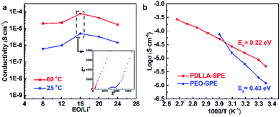
The ionic conductivity of the as-obtained PDLLA-SPEs were investigated systematically, to study the effects of lithium salt concentration (EO/Li+) and temperature. It was reported that the concentration of lithium salt in a polymer electrolyte plays a critical role in its ionic conductivity.31 In order to find a preferred EO/Li+ ratios for high ionic conductivity, the conductivity plot for PDLLA-SPE as a function of the EO/Li+ ratios is presented in Fig. 5a. The ionic conductivity of SPE showed an increase with the EO/Li+ ratio was raised from 8 to 16 and followed by a decrease while the EO/Li+ value was increased further to 24. This is mainly because that the free Li+ carrier increases with the rising of lithium salt concentration at the low concentration range, resulting in a gradual improvement in conductivity. However, with the further increase of lithium salt concentration, the formation of ion pairs lowers the Li+ carrier concentration.29 The highest conductivity of SPE was achieved at a EO/Li+ ratio of 16 and the optimal values are 9.7 × 10⁻⁵ and 8.0 × 10⁻⁶ S cm−1 at 60 and 25 °C, respectively.To further understand the conductivity trend as a function of temperature, the solid electrolyte with an EO/Li+ ratio of 16 was studied. In general, the conductivity of the SPE increases with rising temperature from 30 to 100 °C. It is well known that the mobility of polymer chain is enhanced at higher temperatures, which favors the complexation and dissociation of Li+ with polymer segments and accelerates the transfer rate of Li+. In addition, the lithium salt, LiTFSI, has a higher degree of dissociation, resulting in a further improvement of ionic conductivity.32 As a control, the temperature-dependent ionic conductivity of PEO-SPE with the same lithium salt concentration was also tested, as presented in Fig. 5b. It is obvious that the PDLLA-SPE has a higher conductivity than that of PEO-SPE in the temperature range of 25 to 50 °C. This is most likely due to the non-crystalline structure of PDLLA-SPE, as illustrated by the results of DSC and XRD. The higher conductivity of PEO-SPE over that of PDLLA-SPE at 60 °C is attributed to the melting of PEO crystals at elevated temperature, resulting in an amorphous morphology and an enhanced ionic conductivity. The classical Arrhenius theory30,33,34 was used to fit the polymer electrolyte conductivity by eqn (2):
σ = σ0![[thin space (1/6-em)]](https://www.rsc.org/images/entities/char_2009.gif) exp(−Ea/kT) exp(−Ea/kT)
| (2) |
Thermal property and crystallization behavior of PDLLA-SPEs
Thermal property of the PDLLA-SPE plays an important role in the practical application of SPE in lithium ion batteries, which was characterized by DSC and TGA. Fig. 6a shows the DSC curves of SPEs as a function of lithium salt concentrations. The PDLLA-SPEs show no melting peak in the scanning temperature range, which implies the PDLLA-SPEs are amorphous. The glass transition temperatures (Tg) at 40–50 °C are obviously attributed to PDLLA, as reported in literature.18 Notably, the Tgs of the PEG segments were elevated by the increase of the lithium salt concentration, to the values of −48, −46, −42, −36 and −34 °C, respectively. This is attributed to the formation of complex between Li+ and polymer chains when the van der Waals interactions increase with lithium salt concentration.14,29,36,37 According to the free-volume transport mechanism,38 the mobile of the polymer segments favors the transport of free ion.39 In other words, polymers with higher Tg would restrict the migration of carriers. Thus, a lower Tg (or a lower lithium concentration) is more favorable for Li+ transport in SPEs. It is noteworthy that when EO/Li+ is greater than 16, although the Tg is lower, a satisfied conductivity cannot be achieved due to the low the carrier concentration resulting from the barren lithium salt concentration. As a consequence, there must be an optimal EO/Li+ ratio for PDLLA-SPE, at which the influence from Tg and carrier concentration can be balanced. In our case, the optimum value of EO/Li+ of PDLLA-SPE is 16, which was proved by EIS (as shown in Fig. 5a).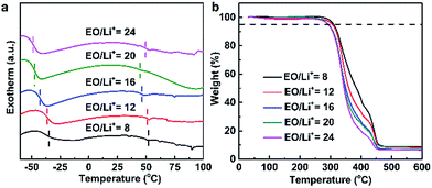 | ||
| Fig. 6 The thermal property of the prepared PDLLA-SPEs with different lithium salt concentrations: (a) DSC curves, (b) TGA thermograms. | ||
The thermal stability of the PDLLA-SPEs was investigated by TGA, as shown in Fig. 6b. The TGA curves of SPE membranes with different lithium salt concentrations show basically the same trend. All samples show a common first stage of weight loss at about 270 °C, due to the decomposition of polymer matrix, slightly higher than the reported value of 240 °C of PDLLA-b-PEG copolymers.18 The second stage of weight loss at approximately 360–450 °C is attributed to the decomposition of LiTFSI.40 In summary, the SPE in this work is thermal stable, and are capable to fully meet the demands of practical application of solid state lithium ion battery.
X-ray patterns depicted in Fig. S2† were employed to identify the phases of PDLLA-SPE and PEO-SPE with the molar ratio of EO/Li+ = 16![[thin space (1/6-em)]](https://www.rsc.org/images/entities/char_2009.gif) :
:![[thin space (1/6-em)]](https://www.rsc.org/images/entities/char_2009.gif) 1. The XRD pattern of PEO-SPE shows strong crystalline peaks at 19.1° and 23.4°, as reported elsewhere.41–44 The degree of crystallinity of PEO-SPE was calculated to be approximately 25%. The high degree of crystallinity leads to a poor ionic conductivity of PEO-SPE at room temperature.4 In sharp contrast to PEO-SPE, only a broad peak located at around 20° is observed in the XRD curves of PDLLA-SPE, implying that the PDLLA-SPE is totally amorphous and meanwhile the added LiTFSI is completely dissolved in the polymer matrix.45 The obtained result corroborate very well with the DSC results. The highly amorphous nature of PDLLA-SPE contributes significantly in ionic conductivity.
1. The XRD pattern of PEO-SPE shows strong crystalline peaks at 19.1° and 23.4°, as reported elsewhere.41–44 The degree of crystallinity of PEO-SPE was calculated to be approximately 25%. The high degree of crystallinity leads to a poor ionic conductivity of PEO-SPE at room temperature.4 In sharp contrast to PEO-SPE, only a broad peak located at around 20° is observed in the XRD curves of PDLLA-SPE, implying that the PDLLA-SPE is totally amorphous and meanwhile the added LiTFSI is completely dissolved in the polymer matrix.45 The obtained result corroborate very well with the DSC results. The highly amorphous nature of PDLLA-SPE contributes significantly in ionic conductivity.
Electrochemical stability of SPEs
The electrochemical stability of the polymer electrolyte probed by linear voltammetry scan is depicted in Fig. S3.† As a comparison, the PEO-SPE prepared by traditional solution casting method (EO/Li+ = 16) was used as a control at the same condition. As shown in Fig. 8, the current density shows a steep increase at 4.7 V versus Li/Li+ at 60 °C for PEO-SPE, which represents the oxidative decomposition of electrolyte.46 However, the LSV curve of PDLLA-SPE is significantly smoother and no oxidation is observed below 5.1 V. Clearly, PDLLA-SPE has a wider electrochemical window and higher electrochemical stability. This is mostly likely due to the existence of ester groups in PDLLA which shows good electrochemical stability, as reported previously.16,47Cell performance
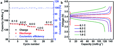
To verify the feasibility of the as-prepared SPEs, the LFP/SPE/Li batteries were assembled to test the durable rate capability and long-term cycling stability. The mass loading of the active materials was 0.96 mg cm−2 in the LFP/SPE/Li batteries. The rate performance of LFP/SPE/Li at 60 °C with the current density of 0.1C to 1.0C is shown in Fig. 7a. It can be found that the discharge capacities are 145.3, 142.5, 134.3, 120.3 and 142.3 mA h g−1, at various current rates of 0.1C, 0.2C, 0.5C, 1C and 0.1C, respectively. The discharge capacities are much higher than those of PEO-SPE reported.48Fig. 7b presents the charge/discharge performance of PDLLA-based Li/LiFePO4 cell at 60 °C with different current densities. The initial specific discharge capacities at different current density show the same trend compared with the rate capacity shown in Fig. 7a. With the increase of current density, the capacity decreases and is maintained at 120.3 mA h g−1 at 1C (82.8% of the capacity at 0.1C). Moreover, the cell exhibits a low polarization voltage at 0.1C with flat voltage plateaus around 3.4 V, which means a good electrochemical reversibility for the cell using PDLLA-SPE.49,50 Even though the polarization voltage gradually enlarges with the rate increasing, the discharge capacity almost recovers completely when the rate is finally returned to the initial 0.1C, which conforms the PDLLA-SPE is structurally and electrochemically stable.
Fig. 8 shows the cycling performance of all-solid-state LFP/SPE/Li batteries at the current density of 0.2C at 60 °C. The initial discharge capacity of LFP/PDLLA-SPE/Li is 144.7 mA h g−1 and remains 125.8 mA h g−1 after 250 cycles. The capacity retention rate is about 86.9%. The initial discharge capacity of the conventional LFP/PEO-SPE/Li shows a similar value of 140.4 mA h g−1, but with a significantly lower capacity retention rate of 77.5% (108.9 mA h g−1) under the same conditions. It's obvious that the cycling performance of the integrated LFP/PDLLA-SPE/Li is much better than that of the conventional one. This superiority is probably ascribed to the better interfacial compatibility between PDLLA-SPE and two electrodes.51 Besides, the PDLLA-SPE is entirely amorphous as discussed above, which may also contribute to the improved cycling performance. In addition, the coulombic efficiency is almost 100% during the long-term cycling process, further verifying the extraordinary cycling reversibility of PDLLA-SPEs.
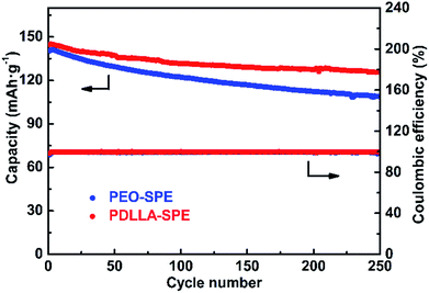 | ||
Fig. 8 The cycling performance of PDLLA-SPE and PEO-SPE with the molar ratio of EO/Li+ = 16![[thin space (1/6-em)]](https://www.rsc.org/images/entities/char_2009.gif) : :![[thin space (1/6-em)]](https://www.rsc.org/images/entities/char_2009.gif) 1 at 60 °C at the current density of 0.2C. 1 at 60 °C at the current density of 0.2C. | ||
Conclusions
In this study, a series of novel SPEs based on a star-comb PDLLA–PEG copolymer and LiTFSI were prepared through solvent-free radical polymerization irradiated by UV. The chemical structure of the obtained polymers was characterized by 1H NMR and FTIR. The surface of the free-standing PDLLA-SPE membranes is smooth and homogenous, as observed by SEM. The phase of the PDLLA-SPEs is totally amorphous, as conformed by XRD. The thermal and electrochemical properties and cell performance of these electrolytes were investigated. The PDLLA-SPEs exhibit good thermal stability with Td5%s of ∼270 °C and low Tgs of −48 to −34 °C. The optimal ionic conductivities are 9.7 × 10⁻⁵ S cm−1 and 8.0 × 10⁻⁶ S cm−1 at 60 °C and 25 °C, respectively, at an EO/Li+ ratio of 16![[thin space (1/6-em)]](https://www.rsc.org/images/entities/char_2009.gif) :
:![[thin space (1/6-em)]](https://www.rsc.org/images/entities/char_2009.gif) 1. Besides, the PDLLA-SPEs has a wide electrochemical window up to 5.1 V, which is much wider than that of PEO-SPE. Furthermore, the all-solid-state LiFePO4/Li cell displays extraordinary cycling and rate performance at 60 °C due to the good interfacial compatibility between PDLLA-SPE and electrodes. In conclusion, the promising cycling and rate performance, together with a relatively high ionic conductivity of the six-arm star-comb PDLLA-SPE make it a attractive candidate of solid polymer electrolyte for all-solid-state lithium batteries.
1. Besides, the PDLLA-SPEs has a wide electrochemical window up to 5.1 V, which is much wider than that of PEO-SPE. Furthermore, the all-solid-state LiFePO4/Li cell displays extraordinary cycling and rate performance at 60 °C due to the good interfacial compatibility between PDLLA-SPE and electrodes. In conclusion, the promising cycling and rate performance, together with a relatively high ionic conductivity of the six-arm star-comb PDLLA-SPE make it a attractive candidate of solid polymer electrolyte for all-solid-state lithium batteries.
Conflicts of interest
There are no conflicts to declare.Acknowledgements
The authors gratefully acknowledge the financial support from the Natural Science Foundation of Guangdong Province, China (grant no. 2016A030311031), the Fundamental Research Foundation of Shenzhen (grant no. 20170410160631170) and the Postdoctoral Science Foundation (grant no. 2016M590782). The authors are also grateful for the support from the members of the Advanced Polymeric Energy Materials Laboratory, Department of Materials Science and Engineering, South University of Science and Technology of China.Notes and references
- J. M. Tarascon and M. Armand, Nature, 2001, 414, 359–367 CrossRef CAS PubMed.
- P. G. Bruce, B. Scrosati and J. M. Tarascon, Angew. Chem., Int. Ed. Engl., 2008, 47, 2930–2946 CrossRef CAS PubMed.
- M. Marcinek, J. Syzdek, M. Marczewski, M. Piszcz, L. Niedzicki, M. Kalita, A. Plewa-Marczewska, A. Bitner, P. Wieczorek, T. Trzeciak, M. Kasprzyk, P. Łężak, Z. Zukowska, A. Zalewska and W. Wieczorek, Solid State Ionics, 2015, 276, 107–126 CrossRef CAS.
- G. B. Appetecchi, F. Croce, L. Persi, F. Ronci and B. Scrosati, Electrochim. Acta, 2000, 45, 1481–1490 CrossRef CAS.
- J. Xi, X. Qiu, M. Cui, X. Tang, W. Zhu and L. Chen, J. Power Sources, 2006, 156, 581–588 CrossRef CAS.
- X.-L. Wu, Y.-H. Li, N. Wu, S. Xin, J.-H. Kim, Y. Yan, J.-S. Lee and Y.-G. Guo, Solid State Ionics, 2013, 245–246, 1–7 CrossRef CAS.
- L. J. Goujon, A. Khaldi, A. Maziz, C. Plesse, G. T. M. Nguyen, P.-H. Aubert, F. Vidal, C. Chevrot and D. Teyssié, Macromolecules, 2011, 44, 9683–9691 CrossRef CAS.
- M.-H. Ryou, Y. M. Lee, K. Y. Cho, G.-B. Han, J.-N. Lee, D. J. Lee, J. W. Choi and J.-K. Park, Electrochim. Acta, 2012, 60, 23–30 CrossRef CAS.
- L. Ding, Polymer, 1997, 38, 4267–4273 CrossRef CAS.
- J.-C. Daigle, A. Vijh, P. Hovington, C. Gagnon, J. Hamel-Pâquet, S. Verreault, N. Turcotte, D. Clément, A. Guerfi and K. Zaghib, J. Power Sources, 2015, 279, 372–383 CrossRef CAS.
- T. Niitani, M. Amaike, H. Nakano, K. Dokko and K. Kanamura, J. Electrochem. Soc., 2009, 156, A577–A583 CrossRef CAS.
- S. Ren, H. Chang, L. He, X. Dang, Y. Fang, L. Zhang, H. Li, Y. Hu and Y. Lin, J. Appl. Polym. Sci., 2013, 129, 1131–1142 CrossRef CAS.
- M. Guo, M. Zhang, D. He, J. Hu, X. Wang, C. Gong, X. Xie and Z. Xue, Electrochim. Acta, 2017, 255, 396–404 CrossRef CAS.
- T. Zheng, Q. Xing, S. Ren, L. Zhang and H. Li, Ionics, 2015, 21, 917–925 CrossRef CAS.
- H.-Y. Wu, D. Saikia, C.-P. Lin, F.-S. Wu, G. T. K. Fey and H.-M. Kao, Polymer, 2010, 51, 4351–4361 CrossRef CAS.
- B. Sun, J. Mindemark, K. Edström and D. Brandell, Solid State Ionics, 2014, 262, 738–742 CrossRef CAS.
- J. Chai, Z. Liu, J. Ma, J. Wang, X. Liu, H. Liu, J. Zhang, G. Cui and L. Chen, Adv. Sci., 2017, 4, 1600377 CrossRef PubMed.
- Y. Lemmouchi, M. Murariu, A. M. D. Santos, A. J. Amass, E. Schacht and P. Dubois, Eur. Polym. J., 2009, 45, 2839–2848 CrossRef CAS.
- R. Auras, B. Harte, S. Selke and R. Hernandez, J. Plast. Film Sheeting, 2003, 19, 123–135 CrossRef CAS.
- K. W. Chew, T. C. Ng and Z. H. How, Int. J. Electrochem. Sci., 2013, 8, 6354–6364 CAS.
- C. H. Tan, A. Ahmad and F. H. Anuar, Asian J. Chem., 2014, 26, S230–S236 CrossRef.
- D. Garlotta, J. Polym. Environ., 2001, 9, 63–84 CrossRef CAS.
- F. Nederberg, E. F. Connor, M. Möller, T. Glauser and J. L. Hedrick, Angew. Chem., Int. Ed., 2001, 40, 2712–2715 CrossRef CAS PubMed.
- Y. Zhao, C. Wu, G. Peng, X. Chen, X. Yao, Y. Bai, F. Wu, S. Chen and X. Xu, J. Power Sources, 2016, 301, 47–53 CrossRef CAS.
- Z.-Y. Wang, H.-J. Zhao, Q.-F. Wang, R.-R. Ye and D. E. Finlow, J. Appl. Polym. Sci., 2010, 117, 1405–1415 CAS.
- F. Carrasco, P. Pagès, J. Gámez-Pérez, O. O. Santana and M. L. Maspoch, Polym. Degrad. Stab., 2010, 95, 116–125 CrossRef CAS.
- S. L. Feng Li, A. El Ghzaoui, H. Nouailhas and R. Zhuo, Langmuir, 2007, 23, 2778–2783 CrossRef PubMed.
- Z.-Y. Wang, Y.-M. Zhao and F. Wang, J. Appl. Polym. Sci., 2006, 102, 577–587 CrossRef CAS.
- M. Marzantowicz, J. R. Dygas, F. Krok, J. L. Nowiński, A. Tomaszewska, Z. Florjańczyk and E. Zygadło-Monikowska, J. Power Sources, 2006, 159, 420–430 CrossRef CAS.
- H. Gupta, S. Shalu, L. Balo, V. K. Singh, S. K. Chaurasia and R. K. Singh, RSC Adv., 2016, 6, 87878–87887 RSC.
- A. Panday, S. Mullin, E. Gomez, N. Wanakule, V. L. Chen, A. Hexemer, J. Pople and N. P. Balsara, Macromolecules, 2009, 42, 4632–4637 CrossRef CAS.
- M. Park, X. Zhang, M. Chung, G. B. Less and A. M. Sastry, J. Power Sources, 2010, 195, 7904–7929 CrossRef CAS.
- D. Kumar and S. A. Hashmi, J. Power Sources, 2010, 195, 5101–5108 CrossRef CAS.
- B. Jinisha, K. M. Anilkumar, M. Manoj, V. S. Pradeep and S. Jayalekshmi, Electrochim. Acta, 2017, 235, 210–222 CrossRef CAS.
- F. Latif, M. Aziz, N. Katun, A. M. M. Ali and M. Z. Yahya, J. Power Sources, 2006, 159, 1401–1404 CrossRef CAS.
- A. Wang, H. Xu, Q. Zhou, X. Liu, Z. Li, R. Gao, N. Wu, Y. Guo, H. Li and L. Zhang, Electrochim. Acta, 2016, 212, 372–379 CrossRef CAS.
- H. Zhang, C. Liu, L. Zheng, W. Feng, Z. Zhou and J. Nie, Electrochim. Acta, 2015, 159, 93–101 CrossRef CAS.
- M. H. Cohen and D. Turnbull, J. Chem. Phys., 1959, 31, 1164–1169 CrossRef CAS.
- J. Mindemark, B. Sun, E. Törmä and D. Brandell, J. Power Sources, 2015, 298, 166–170 CrossRef CAS.
- Z. Lu, L. Yang and Y. Guo, J. Power Sources, 2006, 156, 555–559 CrossRef CAS.
- M. Jaipal Reddy, J. Siva Kumar, U. V. Subba Rao and P. P. Chu, Solid State Ionics, 2006, 177, 253–256 CrossRef CAS.
- S. Song, M. Kotobuki, F. Zheng, Q. Li, C. Xu, Y. Wang, W. D. Z. Li, N. Hu and L. Lu, Solid State Ionics, 2017, 300, 165–168 CrossRef CAS.
- S. Das and A. Ghosh, J. Appl. Phys., 2015, 117, 174103 CrossRef.
- V. K. Singh, S. Shalu, S. K. Chaurasia and R. K. Singh, RSC Adv., 2016, 6, 40199–40210 RSC.
- A. R. Polu, H.-W. Rhee, M. Jeevan Kumar Reddy, A. M. Shanmugharaj, S. H. Ryu and D. K. Kim, J. Ind. Eng. Chem., 2017, 45, 68–77 CrossRef CAS.
- T.-M. Liu, D. Saikia, S.-Y. Ho, M.-C. Chen and H.-M. Kao, RSC Adv., 2017, 7, 20373–20383 RSC.
- K. Kimura, M. Yajima and Y. Tominaga, Electrochem. Commun., 2016, 66, 46–48 CrossRef CAS.
- L. Damen, J. Hassoun, M. Mastragostino and B. Scrosati, J. Power Sources, 2010, 195, 6902–6904 CrossRef CAS.
- Q. Lu, J. Yang, W. Lu, J. Wang and Y. Nuli, Electrochim. Acta, 2015, 152, 489–495 CrossRef CAS.
- B. Chen, Q. Xu, Z. Huang, Z. Yanran, S. Chen and X. Xu, J. Power Sources, 2016, 331, 322–331 CrossRef CAS.
- B. Huang, Y. Zhang, M. Que, Y. Xiao, Y. Jiang, K. Yuan and Y. Chen, RSC Adv., 2017, 7, 54391–54398 RSC.
Footnote |
| † Electronic supplementary information (ESI) available. See DOI: 10.1039/c7ra13664a |
| This journal is © The Royal Society of Chemistry 2018 |

