
 Open Access Article
 This Open Access Article is licensed under a
 Creative Commons Attribution 3.0 Unported Licence
A surfactant-free microemulsion composed of isopentyl acetate, n-propanol, and water†
Yuan Liua,
Jie Xu*a,
Huanhuan Denga,
Jiaxin Songa and
Wanguo Hou *b
*b
aState Key Laboratory Base of Eco-chemical Engineering, Qingdao University of Science and Technology, 266042, Qingdao, P. R. China. E-mail: xujie@qust.edu.cn; Fax: +86-531-88564750; Tel: +86-531-88365460
bKey Laboratory for Colloid and Interface Chemistry (Ministry of Education), Shandong University, 250100, Jinan, P. R. China. E-mail: wghou@sdu.edu.cn
First published on 3rd January 2018
Abstract
It has been demonstrated that in the absence of traditional surfactants, microemulsions can form from a ternary mixture of oil, water, and an amphi-solvent. These microemulsions are called surfactant-free microemulsions (SFMEs). To date, only a small number of SFME systems have been reported, and the current understanding of SFMEs is very limited. Herein, we report an SFME consisting of isopentyl acetate (IA), n-propanol, and water, in which IA (a simple ester compound) and n-propanol are used as the oil phase and amphi-solvent, respectively. The microstructures and structural transition of the SFME were investigated by cyclic voltammetry, fluorescence spectroscopy, and UV-visible spectroscopy techniques. Moreover, three kinds of microstructures, namely, oil-in-water (O/W), bicontinuous (BC), and water-in-oil (W/O), have been identified in the SFME, which are directly verified by cryo-TEM observations. A change in the composition of the SFME may lead to a structural transition from O/W through BC to W/O or vice versa, which is similar to the case of traditional surfactant-based microemulsions (SBMEs). To the best of our knowledge, this is the first time that the microstructures and structural transition of an SFME obtained using a simple ester compound as the oil phase have been identified.
1. Introduction
Surfactant-free microemulsions (SFMEs), just as the name implies, are the microemulsions formed in the absence of traditional surfactants.1,2 As is well-known, traditional microemulsions are currently defined as thermodynamically stable and optically isotropic transparent dispersions formed by at least two immiscible fluids and a surfactant (or an amphiphilic compound).3,4 With reference to the definition of the traditional surfactant-based microemulsions (SBMEs), SFMEs can be defined as thermodynamically stable and optically isotropic transparent dispersions formed by at least two immiscible fluids and an amphi-solvent.2 The two immiscible fluids generally consist of a polar and an apolar component, which are traditionally called the water and oil phases, respectively. The amphi-solvent,2 an amphiphilic substance but not a traditional surfactant, is a solvent that is completely or at least partially miscible with both the water and oil phases; it cannot form micelles in bulk solutions or ordered films at water–oil interfaces. That is, it has no features of traditional surfactants.The first SFME was reported by Smith et al. in 1977,4 and it was found in the ternary system of n-hexane, i-propanol, and water. Subsequently, the formation of SFMEs was confirmed in some surfactant-free ternary systems.5–21 The structures, properties, and formation mechanism of SFMEs have been investigated.1,2,22–24 It has been preliminarily demonstrated that the structures and properties of SFMEs are similar to those of traditional SBMEs to some extent.2 For instance, similar to SBMEs,3 SFMEs can exhibit three structures: oil-in-water (O/W), bicontinuous (BC), and water-in-oil (W/O) structures, and the three kinds of structures can be translated into each other with change in the composition of the system.7,9–11,13–15,19,21 In addition, similar to SBMEs,25 SFMEs are expected to have extensive potential applications2 such as in enzymatic reactions,26 chemical reactions,27–29 and nanoparticle synthesis.30–32 In particular, SFMEs when used as reaction media may avoid some problems, such as complex separation and purification procedures, possible ecotoxicity, and high material cost, caused by the existence of large amounts of surfactants (>10 wt%) in SBMEs.2 However, SFMEs have received very less attention as compared to SBMEs.22 Over the past few decades, more than 10![[thin space (1/6-em)]](https://www.rsc.org/images/entities/char_2009.gif) 000 studies dealing with SBMEs have been reported in the literature,12 whereas less than 60 studies dealing with SBMEs have been reported.2 In addition, less than 20 SFME systems have been reported to date.2 Consequently, the current understanding of SFMEs is still very limited, and many issues about SFMEs need to be studied; one of these issues is to establish whether SFME formation is a general phenomenon. It is desirable to find more SFME systems, which can provide information for understanding the nature of SFMEs.
000 studies dealing with SBMEs have been reported in the literature,12 whereas less than 60 studies dealing with SBMEs have been reported.2 In addition, less than 20 SFME systems have been reported to date.2 Consequently, the current understanding of SFMEs is still very limited, and many issues about SFMEs need to be studied; one of these issues is to establish whether SFME formation is a general phenomenon. It is desirable to find more SFME systems, which can provide information for understanding the nature of SFMEs.
Herein, we report an SFME consisting of isopentyl acetate (IA), n-propanol, and water, in which IA and n-propanol are used as the oil phase and amphi-solvent, respectively. The structures and structural transition of the SFME were investigated using cyclic voltammetry, fluorescence spectroscopy, and UV-visible spectroscopy. Similar to the traditional SBMEs, the SFME exhibits W/O, BC, and O/W structures depending on the composition of the ternary system. The three kinds of structures were confirmed by cryogenic transmission electron microscopy (cryo-TEM) observations. The Kunz group16,20 has investigated the phase behavior of ester-compound-containing ternary systems including geranyl acetate/ethanol/water16 and diethyl adipate/tetrahydrofurfuryl alcohol/deep eutectic solvent (ethylene glycol–choline chloride or urea–choline chloride)20 and revealed the formation of SFMEs in these systems by dynamic/static light scattering and small-angle X-ray scattering measurements. However, the microstructures of the SFMEs were not identified. To the best of our knowledge, this is the first study in which the microstructures and structural transition of an SFME obtained using a simple ester compound as the oil phase have been identified. This study provides a better understanding of SFME construction. In addition, the SFME may have some specific applications, such as in material preparation, reaction engineering, and separation, due to its surfactant-free nature.
2. Experimental
2.1. Chemicals
All the chemicals used in this study were of analytical reagent grade. Isopentyl acetate (IA, purity ≥ 99.5%) and n-propanol (purity ≥ 99.8%) were purchased from Sinopharm Chemical Reagent Co., Ltd., China, and their molecular structures are shown in Fig. S1 in the ESI.† Pyrene (GC grade) was purchased from Sigma-Aldrich, USA. Methyl orange (MO) and potassium ferricyanide (K3Fe(CN)6) were purchased from Tianjin Chemical Reagents Co., China. IA was purified before use by washing with a cold saturated NaCl/NaOH solution (pH = 10–11), drying with 4A molecular sieve, and a final distilling process to remove its free acid impurity. Other chemicals were used as received. Ultrapure water with a resistivity of 18.3 MΩ cm was obtained using an AFZ-1000-U purification system (Chongqing Ever Young Enterprises Development Co. Ltd., China).2.2. Phase diagram construction
The phase diagram of the ternary system IA/n-propanol/water was constructed at 25.0 ± 0.2 °C by titration with n-propanol for IA/water mixtures. An IA/water mixture with a desired volume ratio (RIA/W) was prepared in a dry test-tube. An appropriate volume of n-propanol was added to the mixture under magnetic stirring. The phase boundary was determined by observing the transition from turbidity to transparency or vice versa. Repetition of this experiment for other RIA/W values allowed the phase diagram to be established. The entire procedure was repeated three times, and an average value was used. The component content was expressed as the volume fraction in the ternary phase diagram.2.3. Cyclic voltammetry measurements
Cyclic voltammetry measurements were performed using a CHI model 660D electrochemical workstation (Shanghai Chenhua Instrument Factory, China) with a three-electrode cell, which consisted of a glass-carbon working electrode (electrode area 0.07 cm2), a AgCl/Ag reference electrode, and a Pt wire counter electrode. The space between adjacent electrodes was 2.0 cm. Before each measurement, the working electrode was polished using a 0.05 mm aluminum oxide slurry and then washed carefully with ultrapure water. The electrode was then ultrasonicated in ultrapure water for approximately 5 min before use. The potential was scanned between −0.2 V and 0.8 V, with a sweep rate range of 20–100 mV s−1. All experiments were carried out at 25.0 ± 0.2 °C under a nitrogen atmosphere to avoid oxygen effects. K3Fe(CN)6 was selected as the electroactive probe, with a fixed concentration of 0.65 g L−1.Based on the peak current data obtained at various sweep rates, the diffusion coefficient of the electroactive probe Dp (m2 s−1) in microemulsions can be estimated from the Randles–Sevcik equation:33
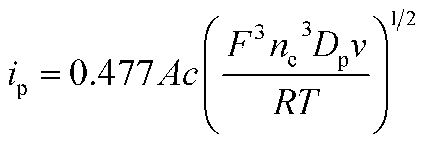 | (1) |
2.4. Fluorescence measurements
Fluorescence emission spectra were obtained using a spectrofluorometer (F-2700, Hitachi, Japan) with a 1 cm path-length quartz cell using pyrene as a fluorescent probe at 25.0 ± 0.2 °C. The pyrene solution in ethanol was placed in a dry test-tube, and ethanol was evaporated by placing the test-tube in a water bath. Appropriate amounts of IA, n-propanol, and water were then added to the test-tube, and the pyrene concentration in the mixture was maintained at 4.95 × 10⁻⁵ mol L−1. The excitation and emission slits were set at a 0.5 nm band-pass. The fluorescence emission spectrum of pyrene from 350 to 420 nm was obtained after excitation at 334 nm. The fluorescence emission spectrum of each sample was obtained after allowing sufficient time (∼48 h) for equilibration.2.5. UV-visible adsorption measurements
UV-visible spectra were obtained using a computer-controlled UV-visible spectrometer (TU-1901, Beijing Purkinje General Instrument Co., Ltd., China), with a 1 cm path-length quartz cell using MO as a probe. Appropriate amounts of IA, n-propanol, and water containing a desired amount of MO were uniformly mixed in advance, and the resultant sample containing 5.0 mg L−1 MO was left for 48 h prior to measurements. The spectrum scanning was carried out at 25.0 ± 0.2 °C with 0.2 nm resolution.2.6. Dynamic light scattering measurements
Dynamic light scattering (DLS) measurements were performed at 25.0 ± 0.2 °C using a Nano ZS90 instrument (Malvern, England) with a 4 mW He–Ne laser (λ = 632.8 nm). Before measurements, the samples were filtered through a polycarbonate membrane (0.45 μm pore size) to remove any dust particles. All the scattering photons were obtained at a 90° scattering angle. The scattering data were analyzed using the CONTIN method to obtain the size distribution and average hydrodynamic diameter (dh) of the test samples. The viscosity and refractive index measurements were carried out using a rotational rheometer (RheolabQC, Anton-Paar, Austria) and an Abbe refractometer (WAY-2S, Shanghai Instrument Physical Optics Instrument Co., Ltd., China), respectively, at 25.0 ± 0.2 °C.2.7. Cryo-TEM observations
Cryogenic transmission electron microscopy (cryo-TEM) observations were performed to determine the structures of microemulsions. The cryo-TEM samples were prepared in a controlled-environment vitrification system (Cryoplunge TM3, USA) at 25 °C and 95% relative humidity. A 4 mL aliquot of the sample was loaded onto a carbon-coated copper grid. The excess solution was then blotted off with filter paper, and a thin film suspended on the mesh holes was produced. After about 5 s, the sample-loaded grid was quickly put in liquid ethane (cooled by liquid nitrogen). The vitrified sample was transferred into a cryogenic specimen holder (Gatan 626) and observed using a JEM-1400 TEM (JEOL, Japan) at approximately −174 °C with an accelerating voltage of 120 kV. The images were obtained using a Gatan multiscan CCD and processed with a Digital micrograph. All samples used for cryo-TEM were filtered through a 0.45 μm filter prior to measurements.3. Results and discussion
3.1. Phase behavior of the IA/n-propanol/water ternary system
Fig. 1 shows the ternary phase diagram of the system IA/n-propanol/water at 25.0 ± 0.2 °C, in which the component content in the system is expressed as the volume fraction (fi, where i represents IA, n-propanol or water). Moreover, two regions are observed in the diagram: one is a single-phase region (blank region), and the other is a multiphase region (shadow region). In the single-phase region, the ternary systems are optically isotropic and transparent, whereas in the multiphase region, they are turbid under stirring and break quickly into two phases when left to stand. The single-phase region occupies about 55% area in the total phase diagram. This diagram indicates that immiscible IA and water can stably coexist in a homogeneous system with the aid of a certain amount of n-propanol. Based on a previous study,2 SFMEs most likely form in the single-phase region. In addition, the single-phase channel extending from oil-rich to water-rich regions obtained herein is suitable for studying the structural transition.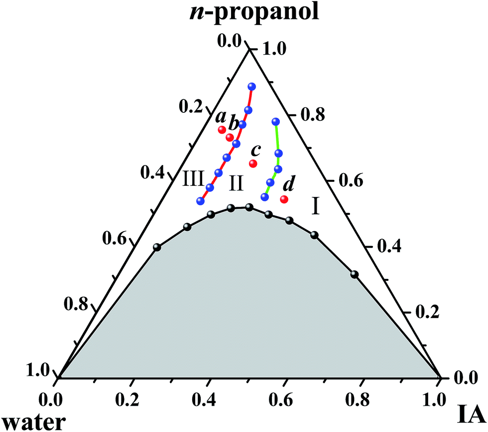 | ||
| Fig. 1 Phase diagram of the IA/n-propanol/water system at 25 ± 0.2 °C. I, II, and III represent W/O, BC, and O/W subregions, respectively. Samples a, b, c, and d were chosen for cryo-TEM observations. | ||
3.2. Structures and structural transition of microemulsions
Along various IA dilution lines with different RP/W values (Fig. S3, ESI†), the change in Dp of K3Fe(CN)6 in the ternary system over the single-phase region was examined. A typical plot of Dp versus fIA for RP/W = 8.0/2.0 is shown in Fig. 2. The Dp decreases monotonically with the increasing fIA over the entire single-phase region. However, two breakpoints are observed in the Dp–fIA plot. The whole curve can therefore be divided into three successive stages: an initial slow decrease, a subsequent quicker decrease, and a final slower decrease, as indicated in Fig. 2. Similar results are obtained for RB/P = 9.5/0.5, 9.0/1.0, 8.5/1.5, and 7.5/2.5 (Fig. S4, ESI†). Based on previous studies,14,15,33,37,38 the discontinuous change in Dp can be attributed to the change in the microstructure of the K3Fe(CN)6-located environment, i.e., a microemulsion forms in the ternary system and its microstructure is changed with a change in fIA. Generally, when an electroactive probe is completely solubilized in dispersed droplets, a lower Dp value will be obtained in comparison with that from a continuous phase. This is because the probe located in droplets diffuses with the droplets, and the obtained Dp value corresponds to the apparent diffusion coefficient of the droplets.37,38 In this study, the electroactive probe K3Fe(CN)6 is expected to preferentially probe the water environment because of its limited solubility in IA. Therefore, the high Dp value at low fIA (e.g., <0.08 for RP/W = 8.0/2.0) suggests the formation of an O/W type microemulsion, which corresponds to the diffusion of the probe in the water-rich continuous phase. The low Dp value at high fIA (e.g., fIA > 0.27 for RP/W = 8.0/2.0) suggests the formation of a W/O type microemulsion, which corresponds to the diffusion of the water-rich droplets. At intermediate fIA (e.g., 0.08 < fIA < 0.27 for RP/W = 8.0/2.0), the change rate in Dp with fIA is different from those at both high and low fIA; this suggests the formation of a BC microstructure.14,15,33,35,37,39,40
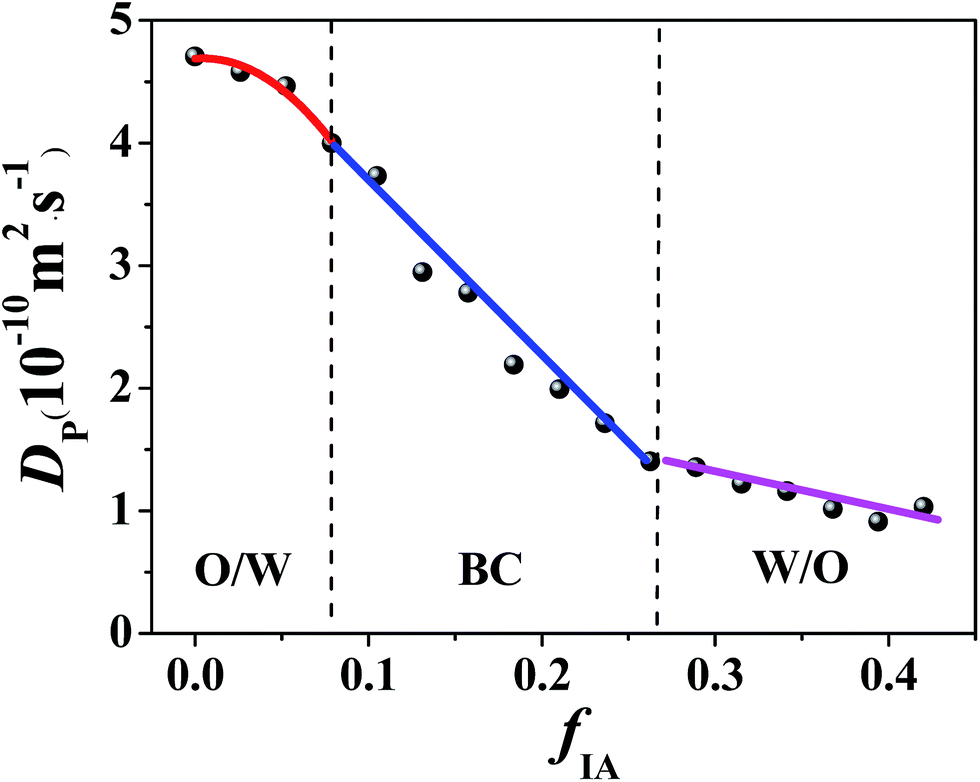 | ||
| Fig. 2 Diffusion coefficient of K3Fe(CN)6 in the IA/n-propanol/water ternary system with RP/W = 8.0/2.0 as a function of fIA. The K3Fe(CN)6 concentration is 0.65 g L−1. | ||
The cyclic voltammetry data demonstrate that with the increasing fIA, a structural transition of the microemulsion occurs, i.e., from O/W through BC to W/O. Notably, only one breakpoint appears for the ternary systems with RP/W = 7.0/3.0, 6.5.0/3.5, and 6.0/4.0 (Fig. S4, ESI†), suggesting that the transition from W/O to BC occurs along the IA dilution lines. Furthermore, no obvious breakpoint appears for the ternary system with RP/W = 5.5/4.5 (Fig. S4, ESI†); this suggests that no phase transition occurs along the IA dilution line.14,21
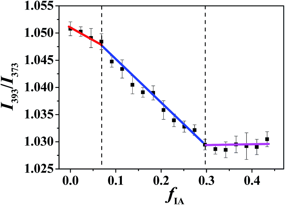 | ||
| Fig. 3 Intensity ratio I393/I373 of pyrene in microemulsions at RP/W = 8.0/2.0 as a function of fIA. The pyrene concentration is 4.95 × 10⁻⁵ mol L−1. | ||
The I393/I373 values of pyrene in bulk water, IA, and n-propanol were determined to be 0.824, 1.035, and 1.075, respectively, indicating that the order of the polarity for the three components is water > IA > n-propanol. In addition, hydrophobic pyrene is expected to preferentially probe the IA microenvironment because of its limited solubility in water. Notably, the IA and water phases in the SFMEs studied herein actually consist of IA/n-propanol and water/n-propanol solutions, respectively, owing to the fact that n-propanol is miscible with both IA and water. With the increasing fIA, the n-propanol content in the IA/n-propanol phase decreases; this may lead to a decrease in I393/I373 owing to the I393/I373 value of n-propanol being higher than that of IA. In addition, the fIA values corresponding to the breakpoints are very close to those observed in cyclic voltammetry measurements (Fig. S5, ESI†). Therefore, the discontinuous change in I393/I373 observed herein can be attributed to the structural transition of the microemulsion with changing fIA. That is, the three changing stages in I393/I373 observed from low to high fIA correspond to W/O, BC, and O/W microstructures. Notably, only one breakpoint appears for the ternary system with RP/W = 7.0/3.0 (Fig. S6B, ESI†), suggesting that only a transition from W/O to BC occurs along the IA dilution line, which is similar to the cyclic voltammetry result.
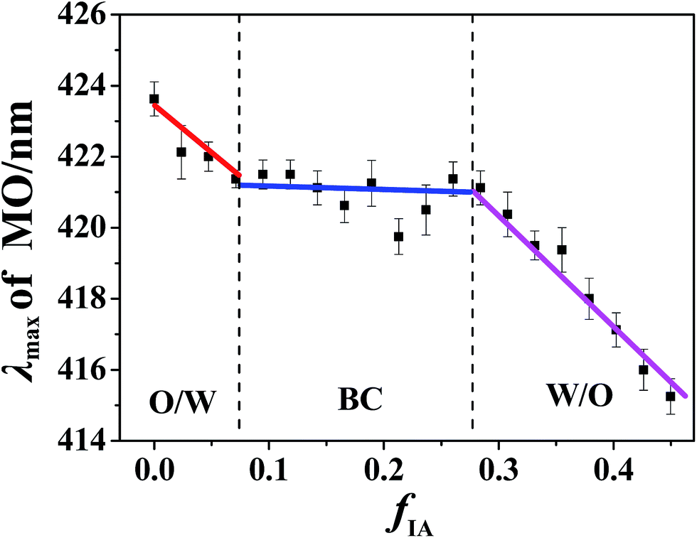 | ||
| Fig. 4 MO λmax as a function of fIA in microemulsions at RP/W = 8.0/2.0. The MO concentration in microemulsions is 5 mg L−1. | ||
3.3. Cryo-TEM and DLS studies
Along the IA dilution line with RP/W = 8.0/2.0, four samples with fIA = 0.050, 0.083, 0.183, and 0.318 (denoted as a, b, c, and d, respectively) were chosen for cryo-TEM observations. The samples a and b fall in the O/W subregion, and the samples c and d fall in the BC and W/O subregions, respectively, as marked in Fig. 1. The cryo-TEM images of the four samples are shown in Fig. 5 (and Fig. S7, ESI†). Spherical droplets are observed for the samples a, b, and d, demonstrating the existence of discrete droplets in the systems. The average diameters of droplets for the samples a, b, and d are measured to be ∼80, 200, and 120 nm, respectively. For the sample c, a network structure (or a sponge-like structure) formed by the interconnection of droplets is observed, corresponding to both IA and water being continuous phases in the microstructure. The cryo-TEM results directly verify the formation of W/O, BC, and O/W microemulsions.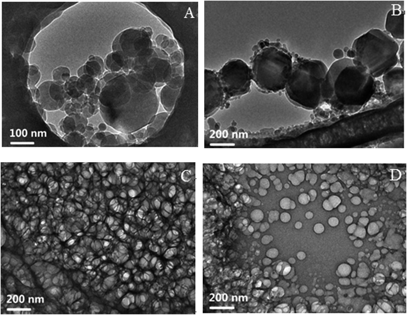 | ||
| Fig. 5 Cryo-TEM images of the samples (A) a, (B) b, (C) c, and (D) d. The samples a and b fall in the O/W subregion, and the samples c and d fall in the BC and W/O subregions, respectively, as marked in Fig. 1. | ||
To further determine the sizes of the dispersed droplets in the W/O and O/W SFMEs, DLS measurements were carried out for the samples a and b in the O/W subregion and the sample d in the W/O subregion (as marked in Fig. 1), as shown in Fig. 6. The dh values of the samples a, b, and d are 77, 198, and 167 nm, respectively, close to their sizes observed by cryo-TEM.
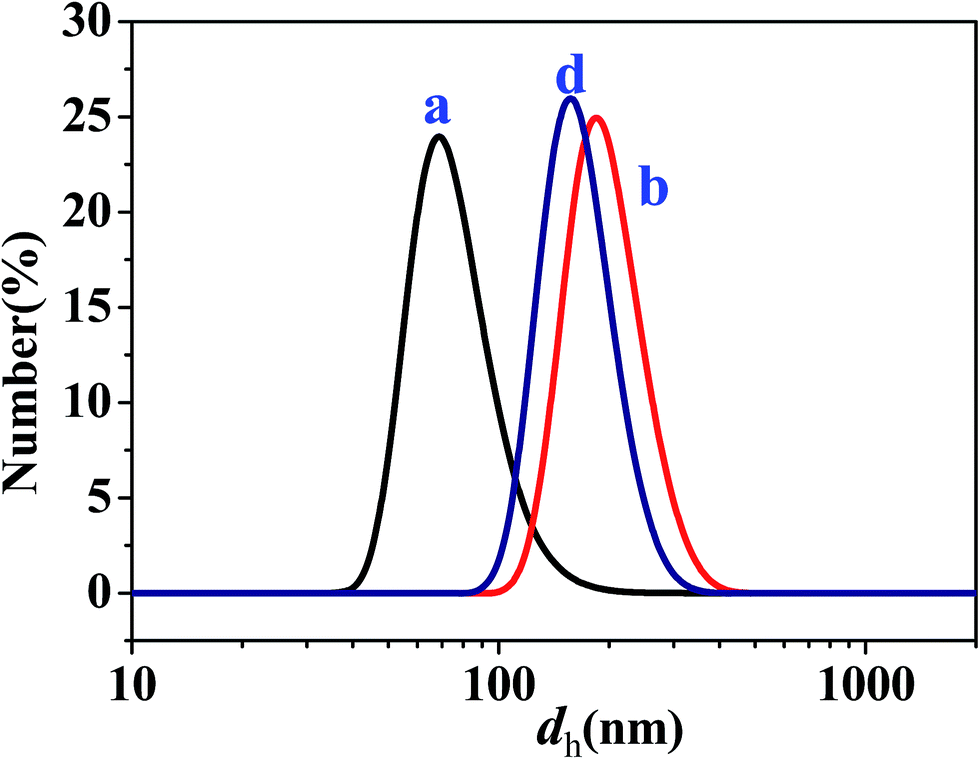 | ||
| Fig. 6 Size distributions of dispersed droplets for the samples a, b, and d as marked in Fig. 1. | ||
3.4. Stability of microemulsions
The stability of the microemulsions was examined by the following processes: (1) heat-storage at 80 °C for one week; (2) cold-storage at −10 °C for one week; (3) freeze (−10 °C)-thaw (40 °C) cycle 3 times; and (4) centrifugation under 100g for 15 min. No changes in the appearance of the microemulsion systems are found after different treatments, which is consistent with the thermodynamic stability characteristics of microemulsions.Notably, the mechanism of the SFME formation is still unclear. The decrease in the isopentyl acetate (IA)/water interfacial tension caused by the addition of n-propanol may play a key role in the formation of the SFME. Most likely, n-propanol is preferentially located in the interphase between IA and water, as suggested in the previous reports.5,20 Many essential questions concerning the nature of SFMEs remain to be addressed.
4. Conclusion
The phase diagram of the ternary mixture of IA (oil phase), n-propanol (amphi-solvent), and water shows a single-phase and a multiphase region. Microemulsions, i.e., SFMEs, form in the single-phase region. The SFMEs may exhibit O/W, BC, and W/O microstructures, which are directly confirmed by cryo-TEM observations. A change in the composition of the SFMEs may lead to a structural transition from O/W through BC to W/O or vice versa, which is similar to the case of traditional SBMEs. This study provides evidence for the speculation that SFME formation may be a general phenomenon. These SFMEs may have specific applications in material preparation, reaction engineering, and separation because of their surfactant-free nature.Conflicts of interest
The authors declare no competing financial interest.Acknowledgements
This work was supported by the National Natural Science Foundation of China (No. 21403121 and 21573133) and the foundation of Key Laboratory of Colloid and Interface Chemistry (Shandong University), Ministry of Education, China (No. 201405).References
- S. Schöttl and D. Horinek, Curr. Opin. Colloid Interface Sci., 2016, 22, 8–13 CrossRef.
- W. Hou and J. Xu, Curr. Opin. Colloid Interface Sci., 2016, 25, 67–74 CrossRef CAS.
- D. J. McClements, Soft Matter, 2012, 8, 1719–1729 RSC.
- G. D. Smith, C. E. Donelan and R. E. Barden, J. Colloid Interface Sci., 1977, 60, 488–496 CrossRef CAS.
- G. Lund and S. L. Holt, J. Am. Oil Chem. Soc., 1980, 57, 264–267 CrossRef CAS.
- J. Lara, G. Perron and J. E. Desnoyers, J. Phys. Chem., 1981, 85, 1600–1605 CrossRef CAS.
- Y. L. Khmelnitsky, A. V. Hoek, C. Veeger and A. J. W. G. Visser, J. Phys. Chem., 1989, 93, 872–878 CrossRef CAS.
- Y. R. Wang, L. L. Duan, S. Q. Cheng, B. Chai and F. Han, J. Dispersion Sci. Technol., 2008, 29, 280–283 CrossRef CAS.
- P. Ni and W. G. Hou, Chin. J. Chem., 2008, 26, 1335–1338 CrossRef CAS.
- P. Ni and W. G. Hou, Chin. J. Chem., 2008, 26, 1985–1990 CrossRef CAS.
- M. L. Klossek, D. Touraud, T. Zemb and W. Kunz, ChemPhysChem, 2012, 13, 4116–4119 CrossRef CAS PubMed.
- J. Xu, A. Yin, J. Zhao, D. Li and W. Hou, J. Phys. Chem. B, 2013, 117, 450–456 CrossRef CAS PubMed.
- J. Xu, L. Zhang, A. Yin, W. Hou and Y. Yang, Soft Matter, 2013, 9, 6497–6504 RSC.
- J. Xu, L. Zhang, C. Li, T. Zhan and W. Hou, RSC Adv., 2013, 3, 21494–21500 RSC.
- J. Marcus, M. L. Klossek, D. Touraud and W. Kunz, Flavour Fragrance J., 2013, 28, 294–299 CrossRef CAS.
- O. Diat, M. L. Klossek, D. Touraud, B. Deme, I. Grillo, W. Kunz and T. Zemb, J. Appl. Crystallogr., 2013, 46, 1665–1669 CAS.
- R. F. Hankel, P. E. Rojas, M. Cano-Sarabia, S. Sala, J. Veciana, A. Braeuer and N. Ventosa, Chem. Commun., 2014, 50, 8215–8218 RSC.
- P. Boškovicć, V. Sokol, T. Zemb, D. Touraud and W. Kunz, J. Phys. Chem. B, 2015, 119, 9933–9939 CrossRef PubMed.
- V. Fischer, J. Marcus, D. Touraud, O. Diat and W. Kunz, J. Colloid Interface Sci., 2015, 453, 186–193 CrossRef CAS PubMed.
- J. Xu, H. Deng, Y. Fu, Y. Chen, J. Zhang and W. Hou, Soft Matter, 2017, 13, 2067–2074 RSC.
- S. Schöttl, J. Marcus, O. Diat, D. Touraud, W. Kunz, T. Zemb and D. Horinek, Chem. Sci., 2014, 5, 2949–2954 RSC.
- P. Guilbaud and T. Zemb, Curr. Opin. Colloid Interface Sci., 2015, 20, 71–77 CrossRef CAS.
- T. N. Zemb, M. Klossek, T. Lopian, J. Marcus, S. Schöettl, D. Horinek, S. F. Prevost, D. Touraud, O. Diat, S. Marčelja and W. Kunz, Proc. Natl. Acad. Sci. U. S. A., 2016, 113, 4260–4265 CrossRef CAS PubMed.
- A. Xenakis, M. Zoumpanioti and H. Stamatis, Curr. Opin. Colloid Interface Sci., 2016, 22, 41–45 CrossRef CAS.
- N. F. Borys, S. L. Holt and R. E. Barden, J. Colloid Interface Sci., 1979, 71, 526–532 CrossRef CAS.
- D. K. Lavallee, E. Huggins and S. Lee, Inorg. Chem., 1982, 21, 1552–1553 CrossRef CAS.
- B. A. Keiser and S. L. Holt, Inorg. Chem., 1982, 21, 2323–2327 CrossRef CAS.
- J. Xu, L. Zhang, D. Li, J. Zhao and W. Hou, Colloid Polym. Sci., 2013, 291, 2515–2521 CAS.
- T. Zhan, Y. Zhang, Q. Yang, H. Deng, J. Xu and W. Hou, Chem. Eng. J., 2016, 302, 459–465 CrossRef CAS.
- J. Xu, H. Deng, J. Song, J. Zhao, L. Zhang and W. Hou, J. Colloid Interface Sci., 2017, 505, 816–823 CrossRef CAS PubMed.
- Y. Gao, S. Han, B. Han, G. Li, D. Shen, Z. Li, J. Du, W. Hou and G. Zhang, Langmuir, 2005, 21, 5681–5684 CrossRef CAS PubMed.
- S. P. Moulik and B. K. Paul, Adv. Colloid Interface Sci., 1998, 78, 99–195 CrossRef CAS.
- M.-J. Schwuger, K. Stickdorn and R. Schomaecker, Chem. Rev., 1995, 95, 849–864 CrossRef CAS.
- K. Chokshi, S. Qutubuddin and A. Hussam, J. Colloid Interface Sci., 1989, 129, 315–326 CrossRef CAS.
- Y. Gao, N. Li, L. Zheng, X. Zhao, S. Zhang, B. Han, W. Hou and G. Li, Green Chem., 2006, 8, 43–49 RSC.
- A. B. Mandal and B. U. Nair, J. Phys. Chem., 1991, 95, 9008–9013 CrossRef CAS.
- P. Guéring and B. Lindman, Langmuir, 1985, 1, 464–468 CrossRef.
- Y. Gao, S. Han, B. X. Han, G. Li, D. Shen, Z. Li, J. Du, W. Hou and G. Zhang, Langmuir, 2005, 21, 5681–5684 CrossRef CAS PubMed.
- C. Mo, Langmuir, 2002, 18, 4047–4053 CrossRef CAS.
- Y. Gao, S. Wang, L. Zheng, S. Han, X. Zhang, D. Lu, L. Yu, Y. Ji and G. Zhang, J. Colloid Interface Sci., 2006, 301, 612–616 CrossRef CAS PubMed.
- P. Lianos, J. Phys. Chem., 1982, 86, 1935–1937 CrossRef CAS.
- R. Sripriya, K. M. Raja, G. Santhosh, M. Chandrasekaran and M. Noel, J. Colloid Interface Sci., 2007, 314, 712–717 CrossRef CAS PubMed.
- D. M. Zhu and Z. A. Schelly, Langmuir, 1992, 8, 48–50 CrossRef CAS.
Footnote |
| † Electronic supplementary information (ESI) available. See DOI: 10.1039/c7ra12594a |
| This journal is © The Royal Society of Chemistry 2018 |