Fabrication of a Au-loaded CaFe2O4/CoAl LDH p–n junction based architecture with stoichiometric H2 & O2 generation and Cr(VI) reduction under visible light†
Snehaprava
Das
,
Sulagna
Patnaik
and
K. M.
Parida
 *
*
Center for Nano Science and Nano Technology SOA Deemed to be University, Bhubaneswar-751030, Odisha, India. E-mail: Kulamaniparida@soa.ac.in
First published on 16th November 2018
Abstract
The search for visible-light-active, highly efficient and durable bi-functional photocatalysts is now essential for the development of various renewable energy sources and conversion technologies. Herein, we report a novel magnetically separable Au-loaded CaFe2O4/CoAl LDH heterostructure with strong coulombic interfacial interactions fabricated through a simple two-step process. XRD, XPS and TEM analysis of the synthesized samples were carried out for the structural and morphological characterization. The TEM study confirmed the existence of a firm attachment between the Au nanoparticles with the CaFe2O4/CoAl LDH heterostructures, which provides a unique support due to an exterior confinement effect. Formation of the heterojunction with a different electronic behaviour was also confirmed from an inverted V-shaped M–S plot, suggesting the presence of a large intimate contact interface between CoAl LDH and CaFe2O4 to favour the efficient separation and transfer of photoinduced charge pairs. The CoAl LDH–CaFe2O4@Au ternary heterostructure showed a high hydrogen generation rate of 379.1 μmol h−1, oxygen evolution rate of 205.5 μmol h−1 and Cr(VI) reduction rate of 99% under visible light irradiation. The CoAl LDH–CaFe2O4@Au heterostructure demonstrated its long-term stability and durability during photocatalytic investigations. The efficient photocatalytic activity of the catalysts was due to the synergistic effect of hot electron transfer by Au nanoparticles and easy mass transport through the interface owing to formation of a p–n junction by increasing the contact area. The mechanism of the photocatalytic activity was also supported by PL, EIS and photocurrent measurements. This work provides a novel strategy to design junction-based nanostructures as a promising photocatalyst for solar energy conversion.
1. Introduction
As a green and sustainable technology, solar-driven heterogeneous semiconductor photocatalysis is of great interest as a possible solution to the global environmental problems and energy-related issues.1–4 The effectiveness of a semiconductor mainly depends on its capability towards absorbing visible light and its ability to suppress electron–hole recombination.5,6 In this regard, the development of suitable photocatalysts with high catalytic activity, desirable selectivity and long-term stability is attracting growing interest for the transformation and purification of targeted pollutants.4,7,8 Although various conventional photocatalysts have been developed over the past decades,9,10 it is highly desirable to explore semiconducting materials with better photocatalytic efficiency. In this context, the discovery of layered double hydroxides gave impetus to their research over other two-dimensional (2D) materials in the field of photocatalysis due to their relatively low cost, environmentally friendly nature, high redox activity and effective utilization of transition metal atoms.11 These 2D layered double hydroxides (LDHs) containing transition metal ions represent a hot topic of research because of the simplistic tenability of their chemical compositions, large surface area, exchangeable interlayer anions and presence of surface hydroxyl groups.12–15 For instance, the intergallery water and hydronium ion of the brucite layer plays a key role in enhancing the photocatalytic activity by enabling effective light absorption, short charge transport distance, strong coupling, thereby improving the surface reaction kinetics along with the electron–hole separation.16 In the last few years, there has been outstanding work performed on binary LDHs with vertically aligned structures exhibiting great potential as photocatalysts, together with several new properties emerging.17–20 Although LDHs have been investigated widely, owing to their poor conductivity and low quantum yield under visible light illumination, they are not yet good enough to solve the global energy and environmental problems.21–23 Their limited photo/electro catalytic performance can be overcome by introducing various modifications to improve their charge transfer and electrical conductivity.In this contribution, here to obtain a highly active and chemoselective CoAl LDH catalyst, an original process was developed based on noble metals with a well-organized and compositionally versatile crystalline material. Many researchers have moved towards improving the photocatalytic activity of LDH-based material by making composites with metal oxides, typically incorporating noble metal nanoparticles, coupled with 2D-layered carbon materials, like g-C3N4@Ni Al LDH,24 NiAl LDH/Fe2O4/RGO,25 Au–Pd/LDH,26 Ag/Zn Ti LDH27 and Ga2O3-modified Mg–Al LDH.28 In this area, our group also carried out research to reduce the electron–hole recombination and developed an LDH-based photocatalytic material by designing NiFe LDH/g-C3N4 for efficient H2 and O2 evolution,29 CeO2/MgAl LDH for efficient H2 evolution,30 Zn Cr LDH/LaFe2O4 towards visible-light-induced H2 evolution,31 while recently Co(OH)2/ZnCr LDH was reported as a capable catalyst for both H2 and O2 evolution,16 Ag@Ag3PO4/g-C3N4/NiFe LDH was shown to be a good catalyst for Cr reduction and phenol oxidation32 and Ag@Ag3VO4/ZnCr LDH – a ternary heterostructure – was reported for improved O2 evolution and phenol degradation.33
Very recently, LDHs have been coupled with spinel ferrites (MFe2O4, where M is a divalent cation) and photocatalytic activities of the prepared composites were investigated in the water reduction/oxidation reaction as well as in the degradation of inorganic pollutants. As an important member of the ferrite family, CaFe2O4 has received much attention owing to its exciting catalytic and magnetic properties.34,35 This narrow band-gap semiconductor has been established to be a promising candidate to harvest visible-light. In this respect, CoAl LDHs were further modified by CaFe2O4 to provide open channels for charge transportation, to enable good electrical contact and ion transport by shortening the diffusion pathways. Therefore, it is highly expected that an improved and effective photo/electrochemical performance of 3D Co–Al LDHs/CaFe2O4 could be achieved.
Hence, to take better advantage of LDH-based photocatalytic materials and to increase their photocatalytic efficiency, we tried to construct an effective heterojunction with CaFe2O4, as an ideal candidate owing to its suitable band-edge positions and high stability. A novel magnetically separable Au-loaded CaFe2O4/CoAl LDH heterostructure having strong coulombic interaction was fabricated through a simple two-step process, in which, Au nanoparticles were attached firmly on CaFe2O4/LDH by means of coulombic interactions and an exterior confinement effect to improve its photocatalytic efficiency through hot electron transport. Formation of the heterojunction with a different electronic behaviour was also confirmed by investigating the electrochemical behaviour of the hybrid photocatalyst. The photocatalytic activity of the photocatalyst was examined by studying its performance in water oxidation/reduction reactions in the presence of various scavengers and by the reduction of hexavalent chromium Cr(VI).
Towards the reduction of inorganic pollutants, like hexavalent chromium and water reduction/oxidation reactions, the CaFe2O4/CoAl LDH heterostructure was demonstrated to be a suitable visible light active photocatalyst. The synergistic effect of CaFe2O4/CoAl LDH heterostructures with a familiar interfacial contact along with hot electron transport by Au NPs contributed to boosting the separation efficiency of photogenerated charge carriers, thus leading to improved photocatalytic activity. In addition, the possible photocatalytic mechanisms for the reduction of Cr(VI) and water and the oxidation of water were also established and are discussed herein in detail.
2. Experimental details
2.1 Materials and preparation
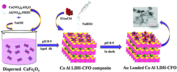
The chemicals required in the material synthesis included Co(NO3)2·6H2O, Al(NO3)3. 9H2O, Ca(NO3)2·4H2O, Fe(NO3)3·9H2O, HAuCl4·4H2O, sodium hydroxide, ethylene glycol, sodium borohydride, diphenylcarbazide, methanol, lactic acid, triethanol amine and silver nitrate and all were of analytical grade (Merck) and used without any further purification. Deionized water was used for preparing solutions throughout the experiments.The synthesis of the ternary hybrid photocatalyst involved mainly three steps: Step 1: synthesis of CaFe2O4 nanocrystals; Step 2: synthesis of Co Al LDH–CaFe2O4 nanocomposite and Step 3: deposition of Au on the Co Al LDH–CaFe2O4 composite.
2.2 Synthesis of CaFe2O4 nanocrystals
The CaFe2O4 nanocrystals were prepared by a simple sol–gel method followed by calcination. In a typical experimental procedure, 50 mL of aqueous solution containing 3 g of Ca(NO3)2·4H2O and 4 g of Fe(NO3)3·9H2O was well stirred for 10 min, and then 1 g of citric acid was added and the mixture was further stirred for 60 min to obtain a transparent solution. To the precursor solution, 3 mL of ethylene glycol was added under stirring and the mixture was gradually heated to 70 °C and this temperature was maintained till the mixture became viscous by slow evaporation. When the critical temperature was reached, a little explosion occurred accompanied by the evolution of a large amount of reddish brown gas, yielding a flate brick red fluffy product. Then, the solid product was finely ground and then calcined in a muffle furnace at 850 °C for 3 h in an alumina crucible to obtained brick red colour CaFe2O4.2.3 Synthesis of the Co Al LDH-CaFe2O4 composite
In order to synthesize the Co Al LDH-CaFe2O4 nanocomposite, a calculated amount of prepared CaFe2O4 was dispersed into 50 mL deionized water and stirred for 30 min to obtain a uniform suspension. Meanwhile, a mixed salt solution of Co(NO3)2·6H2O and Al(NO3)3·9H2O in the molar ratio of 2![[thin space (1/6-em)]](https://www.rsc.org/images/entities/char_2009.gif) :
:![[thin space (1/6-em)]](https://www.rsc.org/images/entities/char_2009.gif) 1 was added dropwise to the suspension and the pH of the solution was maintained around 8–9 by adding 0.1 M NaOH simultaneously. Then the suspension was aged for 6 h and centrifuged till the effluent solution was neutral.
1 was added dropwise to the suspension and the pH of the solution was maintained around 8–9 by adding 0.1 M NaOH simultaneously. Then the suspension was aged for 6 h and centrifuged till the effluent solution was neutral.
2.4 Synthesis of Au-loaded Co Al LDH–CaFe2O4 nanocomposite
The Au-loaded CoAl LDH–CaFe2O4 nanocomposite was synthesised through the borohydrate reduction method. Initially, a specific amount of Co Al LDH–CaFe2O4 composite was dispersed in deionized water and magnetically stirred for 2 h. Then, 8 mL of 0.01 M HAuCl4 acid (1 wt%) was added dropwise with constant stirring in the dark for uniform decoration of the Au nanoparticles on the composite surface. NaOH solution was added to maintain the pH around 8–9. Then, freshly prepared NaBH4 solution in ice cold water was rapidly injected to the aforementioned solution. There was a sudden colour change when NaBH4 is added, which confirmed the formation of Au NPs, as shown in Scheme 1.2.5 Characterization techniques
The structure and crystallinity of the prepared samples were characterized by a Rigaku Ultima-IV XRD instrument having Cu Kα radiation (λ = 0.154 nm) from 5° to 80° at a scan rate of 0.02 °C min−1. The UV-Vis diffusion reflectance spectra of all the synthesized samples were analyzed using a JASCO V-750 spectrophotometer with BaSO4 used as the reference in the range 200–800 nm. The photoluminescence character was analyzed using a JASCO FP-8300 fluorescence spectrometer taking 320 nm as the excitation wavelength. The morphology interaction and the microstructure of the catalysts were studied using a Philips TECNAI G2 electron microscope operated at an accelerating voltage of 200 kV. X-ray photoelectron spectroscopy was performed using a Kartos axis ultra-X-ray photoelectron spectrometer system, which consists of a charge neutralizer and Al Kα X-ray as the monochromatizing source. FTIR spectra of the synthesized samples were studied using a PerkinElmer spectrum RXI FT-IR spectrophotometer in the frequency range of 4000–400 cm−1 with KBr used as the reference dilutant. The SEM images were obtained using an Hitachi S-3400N. All the photo-electrochemical studies of the prepared catalysts were carried out using an IVIUM n STAT instrument with the photocatalyst, platinum and Ag/AgCl acting as the working electrode, counter electrode and reference electrode, respectively. The working electrode was prepared though an electrophoretic deposition technique using FTO with a 300 W Xe lamp used as the light source and 0.1 M Na2SO4 (pH 6.8) as the electrolyte solution. The Nyquist plot was carried out at 105–102 Hz at zero bias. The Mott–Schottky measurement was done at 1500 Hz. Linear sweep voltammetry (LSV) plots were assessed by sweeping the potential from −0.7 to 1 V.3. Photocatalytic experiments
The direct-solar-light-promoted photocatalytic performances of all the synthesized samples were investigated to evaluate the hydrogen/oxygen evolution through the water reduction/oxidation reaction and for the reduction of hexavalent chromium as inorganic pollutants. The reduction activity was studied at different pH values and the rate of reduction was determined by plotting C/Co vs. time. The hydrogen/oxygen evolved and the stability of the photocatalyst were also tested through the water reduction/oxidation reaction using methanol as a hole scavenger and AgNO3 as an electron scavenger for 2 h, and also blank experiments were performed without catalysts for H2/O2 evolution.3.1 Experiments for photocatalytic water reduction/oxidation reaction
The photocatalytic water reduction reaction for all the samples were performed using a 100 mL sealed quartz batch reactor round-bottomed flask and a 150 W xenon lamp (>400 nm) as the irradiation source of light, followed by 1 M NaNO2 as the UV cut-off filter, in which the light source was placed 8.9 cm above the aqueous suspension, which was about 10 cm away from the base of the reactor. The water splitting reaction was carried out by dispersing 0.02 g of powder catalyst in 20 mL of aqueous methanol solution (10%) and 20 mL of 0.05 M AgNO3 aqueous solution (pH = 5.2) with constant stirring, which helped to maintain the uniformity throughout the reaction. N2 gas was pursed in the reactor for 15 min to create an inert atmosphere before the light irradiation. Using a downward displacement method evolved H2 and O2 gas, which was collected and examined by gas chromatography. For each sample, the average value of three photocatalytic water reduction experiments was taken. The water reduction was also carried out by using lactic acid and triethanol amine to optimize the conditions, as shown in Fig. S3.† The apparent conversion efficiency of the synthesized Au-loaded LDH–CFO composite was calculated as follows:3.2 Experiment for photocatalytic Cr(VI) reduction
The photocatalytic activity of the synthesized materials was analyzed by monitoring the reduction of highly carcinogenic inorganic pollutant hexavalent chromium under direct sunlight irradiation in the day time between 10:00 and 12:00 noon. All the experiments were carried out from prepared 100 mg L−1 stock chromium solution. The experimental set-up involved a conical flak containing 20 mL of 20 ppm Cr(VI) solution with 20 mg of catalyst. The solution's pH was kept at pH 4, which was found to be optimal among pH = 4, 5, 6, 7 and 9. To achieve sorption equilibrium, the solutions were stirred for 30 min in the dark before being exposed to sunlight. After that, the samples were placed under sunlight for 1 h with stirring. The aliquot solution was separated through centrifugation. The reduction percentage was determined using a JASCO 750 UV-Visible spectrophotometer.4. Results and discussion
4.1 Structural, morphological and surface characterizations (XRD, FTIR, XPS, SEM, TEM)
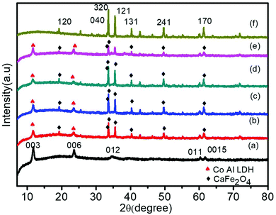
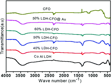
To examine the crystal structure, composition and phase purity of the prepared nanomaterials, XRD analysis was carried out and the corresponding profile planes are shown in Fig. 1. The parent LDH's diffraction peaks (003), (006) and (012) at low angle are sharp and symmetrical. An interlayer spacing of 0.85 nm (d003) showed the presence of nitrate ions and water molecules in the interlayer galleries.36,37 Moreover, the peaks at (011) and (0015) represent high angle asymmetrical peaks without any impurity, indicating a rhombohedral symmetry (R3M) of Co Al LDH, in agreement with (JCPDS no. 51-0045). The diffraction patterns at 2θ = 33.4°, 33.6°, 35.5°, 25.5°, 19.2°, 40.3°, 46.4°, 49.7°, 61.3°, 50.4°, 19.2° and 71.6° are in accordance to JCPDS no. 00-019-0219, thus confirming the formation of CFO with the orthorhombic phase belonging to the space group pnam (S.G. 62). The highly noisy XRD pattern was due to the fluorescence from the Fe atoms.38,39 It was observed that upon Au loading, the crystal structure of LDH was not affected but the peak intensity of the CFO was a bit decreased because of the deposition of Au NPs on the CFO surface.40 No characteristic diffraction peak for Au NPs was observed due to their small content and good distribution.41 The presence of Au NPs was well supported by the XPS and TEM analysis.The molecular structure of the prepared samples and host–guest interactions in the case of the composites were further confirmed from the characteristic vibrational–translational modes. By using an FTIR spectrophotometer, the presence of different functional groups in the prepared samples were also ascertained. Fig. 2 represents the FTIR spectra of all the prepared samples. In the case of neat Co–Al LDH, a broad and strong band at 3436 cm−1 is mainly attributed to the O–H asymmetrical and symmetrical stretching vibrations of interlayer water molecules.42 A weak band at about 3080 cm−1 shows the presence of hydrogen bonds present in the interlayer anions.42 The bending vibration mode of H2O was found at 1616 cm−1, while another absorption band around 800 cm−1 was attributed to the metal–oxygen (M–O) stretching and bending vibrational modes.42 The prominent peaks at 1113, 764, 632 and 541 cm−1 represent the stretching vibration of neat CFO.43 The LDH–CFO composite shows almost the same pattern of FTIR spectrum similar to LDH and CFO, indicating the co-existence of both in the composite. However, the peak positions were slightly shifted to a lower wavenumber, confirming the good interactions in the composite. Owing to NO3− intercalation, a peak at 1384 cm−1 was observed for the N–O stretching vibration mode.44 Due to NO3− intercalation, LDH has a wide interlayer spacing and an adequate anion exchange of LDH, which results in favourable conditions for the subsequent delamination.
XPS measurements were performed to determine the detailed information regarding the oxidation state of various elements on the surface and the chemical environment around them. The wide spectrum of XPS ascribed the presence of Co, Al, Ca, Fe, O and Au in the ternary heterostructure without any additional peak. The obtained elemental XPS peaks were de-convoluted by CASA XPS software to explore the fine detail of the content elements, as shown in Fig. 3.
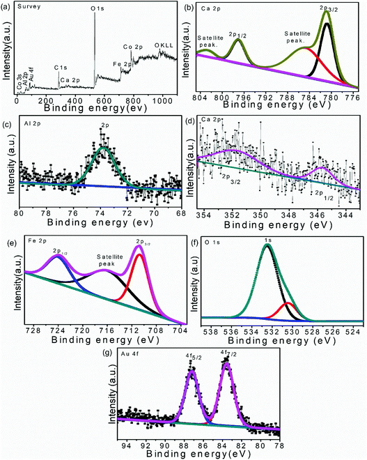 | ||
| Fig. 3 XPS spectra of 50%-LDH–CFO@ Au heterostructure: survey spectrum (a), Co 2p (b), Al 2p (b), Ca 2p (c), Fe 2p (d), O 1s (e), Au 4f (g). | ||
As per the reported results, the high-resolution Co 2p XPS spectrum should describe the spin orbital splitting of Co into Co 2p3/2 (780.5 eV) and Co 2p1/2 (796.7 eV) along with two satellite peaks at 785.5 and 802.1 eV.45,46 However, the Co 2p XPS spectrum in 50% CoAl LDH–CFO@Au (Fig. 3b) showed Co 2p1/2 (780.73 eV) and Co 2p3/2 (797.14 eV) components accompanied by two satellite peaks at 784.95 and 802.64 eV, respectively, indicating a high spin Co2+ state. The observed binding energy of Al (2p) (Fig. 3c) obtained at 73.8 eV agreed with the presence of Al(OH)3 in the brucite-like layers of LDH, which were reported to be at 74.8 eV in the case of pure Al(OH)3.47,48 Compared to the neat counterparts, the positive and negative shift in binding energy of Co and Al confirmed the changes of the chemical states and good interaction between Co and Al in the prepared LDH.
Moreover, the Ca 2p peaks (Fig. 3d) upon deconvolution resulted in two peaks centered at binding energies of 345.7 and 351.79 eV, which were slightly shifted to lower values than the reported characteristics peak of Ca 2p3/2 (346.7 eV) and Ca 2p1/2 (348.2 eV).49 Similarly, three dominant XPS peaks (Fig. 3e) at 710.6, 724.02 and 716.15 eV correspond to binding energies of Fe 2p3/2 and Fe 2p1/2 along with a satellite peak, respectively, representing the Fe3+ state of Fe. These XPS peaks of Fe were also found to be shifted to lower binding energies in comparison to previously reported values of CFO (Fe 2p3/2, Fe 2p1/2 at 711.5 and 725.3 eV, respectively).42,50 The O 1s spectrum (Fig. 3f) shows two peaks centred at 530.3 and 532.4 eV. The peak at 532.3 eV corresponds to the loosely bound oxygen or hydrated oxygen on the sample surface, whereas the peak at 530.3 eV was mainly assigned to oxygen in the sample lattice bonded with Ca2+ and Fe3+.42,51
After combination, a slight shift towards a lower binding energy of Ca and Fe was observed in 50% CoAl LDH–CFO@Au, indicating the involvement of the core level electrons of those metals and oxygen. Thus the above XPS results clearly explain the formation of a heterojunction between CoAl LDH and CFO rather than a simple physical mixture.
The XPS spectra of Au 4f7/2 and Au 4f5/2 were reported to show two peaks located at 83.6 and 87.3 eV, respectively, representing the spin orbit splitting of metallic Au(0) separated by approx. 3.7 eV.52 In 50% CoAl LDH–CFO@Au, (Fig. 3g) the XPS spectra of Au 4f7/2 and Au 4f5/2 located at 83.50 and 87.15 eV, were slightly shifted to lower binding energies in comparison to the reported values. This further confirmed a strong interaction between Au NPs on the LDH–CFO surface.53,54 Moreover, the negative shift in binding energy of Au indicated a transfer of electrons from the surface of Au NPs to the surface of the heterojunction, which are responsible for the enhanced photocatalytic activity.55,56 Further, a more efficient transfer of electrons between the substrate to the metal nanoparticles proved there was a good interaction between Au nanoparticles and the 50% CoAl LDH–CFO surface.
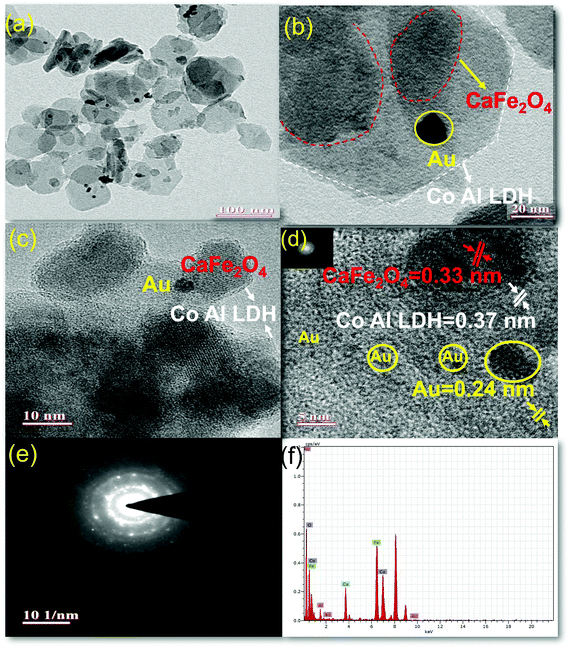
The morphologies and microstructure of the prepared sample 50% LDH CFO@Au was further investigated by TEM, as shown in Fig. 4. From Fig. 4d, it is noticeable that on the LDH and CFO surface, 5–8 nm Au nanoparticles are evenly deposited, thus maintaining the crystallinity, as evidenced by the well-defined lattice fringes. The interplanar distance of 0.24 nm correspond to the 111 plane of Au.57
Hexagonal LDH serves as a good support for metal (Au) nanocrystalline along with preventing the sintering of metal nanoparticles by means of an exterior confinement effect from the LDH layers,58 whereby there is a stable attachment among hexagonal LDH nanoplates and gold nanoparticles as the hydroxide ion of LDH provides a unique support for gold nanoparticles58 and gold nanoparticles get attached on CFO at the bridged O-sites through electrostatic interaction. In the investigation of hybridization between LDH and CFO, an irregular sphere-like black shadow was observed on the hexagonal LDH sheet, representing the CFO with a fringe spacing of 0.33 nm, representing the 040 plane. This strong interaction between LDH and CFO in their composite was due to coulombic interactions between the negatively charged hydroxyl ion of LDH and CFO.
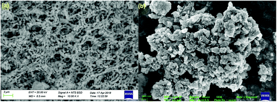
Further SEM analysis was performed to study the morphology of the prepared photocatalyst. Fig. 5 shows the SEM images of the neat CaFe2O4 and 50% LDH–CFO@Au (a and b), respectively. As observed, the CaFe2O4 nanoparticles were present with an irregular interconnected spherical morphology with regular agglomeration forming a 3DOM-like structure. After hybridization of CaFe2O4 and LDH, CaFe2O4 nanoparticles were found to be very well interrelated and fused together, maintaining an open structure for better adsorption and providing a greater number of reaction sites for photocatalytic activity.
4.2 Study of optical properties (UV-Vis DRS, PL)
For study of the optical properties, PL spectroscopy is considered an important approach to give insights regarding the efficiency of separation between the photoinduced electron–hole pairs and the charge-carrier transformation. Fig. 6 shows the PL spectra of all the prepared heterostructures along with neat CFO. It was observed that the PL emission spectra obtained with an excitation wavelength at 320 nm resulted in a more intense peak at 402 nm and a weak shoulder peak at 454, corresponding to a blue emission peak.59 These emission peaks may be initiated from excitonic PL and ascribed to defects due to surface oxygen vacancies.60 Furthermore, it was observed that CoAl LDH exhibited two emission spectra at 401.3 and 448 nm, due to ligand field splitting, in agreement with 4A2g–4T1g (F) and 4T2g–4T1g (F) transitions stated for octahedral cobalt(II) compounds, thus reducing the electron and hole recombination, but not very significantly.61,62 However, an increase in the content of CaFe2O4 significantly delayed charge recombination. The spectra clearly specify that 50% LDH CFO–Au showed substantially reduced luminescence intensity, revealing minimization of electron–hole recombination by the deposition of Au NPs. Here the Au NPs act as a hot electron provider at the interface of p–n heterostructures, proving a direct pathway for efficient charge separation and transport.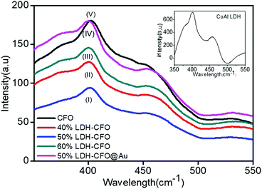 | ||
| Fig. 6 Photoluminescence (PL) emission spectra of neat Co Al LDH and CFO with various heterostructures. | ||
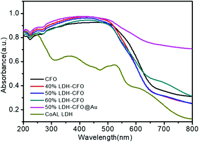
Fig. 7 represents the optical absorption behaviour of the CoAl LDH, CFO and the heterostructures in order to help understand the optical behaviour. The prepared Co Al LDH showed absorption peaks mainly due to the d–d transition of Co2+(d5) cations.63,64 For Co Al LDH, the characteristic band edge around 245 nm was identified as being due to O2− → Co2+ charge-transfer transitions, while the three component absorption peak positioned at ∼450, 500, 525 nm was ascribed to Co2+ in an octahedral co-ordination.65,66 The absorption edge of prepared Co Al LDH was displayed at about 616 nm and the calculated band gap energy was 2.02 eV, as shown in Fig. S1a.†![[thin space (1/6-em)]](https://www.rsc.org/images/entities/char_2009.gif) 67 For pure CFO, a broadening of the absorption peak from 235 nm to 564 nm was observed with an adsorption edge around 688 nm, corresponding to the direct band absorption of CFO (Eg = 1.93 eV), as shown in Fig. S1b.†
67 For pure CFO, a broadening of the absorption peak from 235 nm to 564 nm was observed with an adsorption edge around 688 nm, corresponding to the direct band absorption of CFO (Eg = 1.93 eV), as shown in Fig. S1b.†![[thin space (1/6-em)]](https://www.rsc.org/images/entities/char_2009.gif) 68 Also, the recorded optical spectra of LDH–CFO composite showed a greater broadening of absorption peaks than neat CoAl LDH with a direct band gap of 1.96 eV, as shown in Fig. S1c.† Remarkably, the existence of Au nanoparticles boosted the light absorption range to the IR region due to the SPR effect.69 The successful modification of Co Al LDH–CFO after gold loading could be identified by the naked eye by the colour change from dark brick red to brown with a band gap of 2.0 eV, as shown in Fig. S1d.† This facilitated the formation of a greater number of photoexcitation charge pairs and ultimately improved the photocatalytic activity.
68 Also, the recorded optical spectra of LDH–CFO composite showed a greater broadening of absorption peaks than neat CoAl LDH with a direct band gap of 1.96 eV, as shown in Fig. S1c.† Remarkably, the existence of Au nanoparticles boosted the light absorption range to the IR region due to the SPR effect.69 The successful modification of Co Al LDH–CFO after gold loading could be identified by the naked eye by the colour change from dark brick red to brown with a band gap of 2.0 eV, as shown in Fig. S1d.† This facilitated the formation of a greater number of photoexcitation charge pairs and ultimately improved the photocatalytic activity.
4.3 Electrochemical study (EIS, Bode's plot, LSV and MS plot)
In order to investigate the mechanistic approach of photochemical reactions in the Co Al LDH–CFO and Co/Al LDH–CFO@Au heterostructures, various photoelectrochemical measurements (EIS, Bode's plot, LSV and MS) were carried out.Electrochemical impedance spectra (EIS) of all the prepared photocatalysts were studied to investigate the charge-separation efficiency and charge-transfer resistance under illumination. For all the samples, the Nyquist plots were semicircular in shape. The diameter of the semicircle in a Nyquist plot is related to the resistance offered for the electron-transfer kinetics of the redox probe at the semiconductor/electrolyte interface. The smaller the radius of the semicircle, the smaller the resistance and the faster the rate of charge transfer. As shown in Fig. 8a, the plot consists of a straight line and a depressed semicircle representing the lower and higher frequency regions, respectively, related to the charge separation and transfer process. The smallest semicircle and vertical line indicate the high electronic and ionic conductivity of the Co/Al LDH–CFO@Au nanoparticles as Au NPs act as a hot electron provider in the composite.57 The lower frequency region (straight line part), related to Warburg impedance (Ws), results from the transfer/diffusion of ions in the electrolyte. A small Warburg region is clearly visible from Fig. 8a in the case of Co/Al LDH–CFO@Au and larger in Co/Al LDH–CFO. The smaller Warburg region of the Co/Al LDH–CFO@Au as compared to 50% Co Al LDH–CFO specifies that the movement of ions is more effective within the pores of the composite, which favours the high photocatalytic performance.
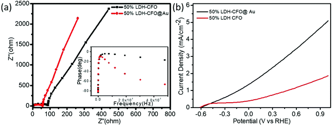 | ||
| Fig. 8 Electrochemical impedance spectra (EIS) (a) and polarization curve (b) of 50% LDH–CFO and 50% LDH–CFO@Au under visible light irradiation. | ||
The Bode phase equation τn = (1/2Πfmax) is used to determine the excited electrons lifetime (τn). The relationship between a single characteristic peak (fmax) and lifetime of the photogenerated electron (τn) is clearly understood from Bode phase plot. As observed in Fig. 8a, the shifting of the peak from a higher to lower frequency region prompts more the electron transfer. The 50% LDH–CFO@Au electrode shows 85.84 μs, which is shorter than that of the 50% LDH–CFO electrode (52.02 μs), signifying an efficient separation and migration of excited electrons of Au-deposited LDH–CFO, suggesting a greater lifetime of excited electrons.57
As shown in Fig. 8b, the LSV curves for binary and ternary hybrid electrodes showed a good photoresponse under visible light irradiation. After incorporating Au NPs, 50% Co/Al LDH–CFO@Au showed a much higher photocurrent than 50% Co/Al LDH–CFO in the observed potential window. Corresponding to the nature of the photocatalysts, the anodic polarization curves studied in the range of −0.6 to 1.0 V showed an increase in the oxidation potential of the composites. The 50% Co/Al LDH–CFO@Au (5.01 mA cm−2) provided a much higher anodic photocurrent than the 50% Co Al LDH–CFO (1.8 mA cm−2) as the photogenerated electron–hole separation occurs more rapidly, producing 2.8 times more photocurrent. From the LSV measurement, it was considered that the charge separation efficiency rises with the applied voltage as the surface charge layer is widened. The deposited Au NPs can provide a greater number of hot electrons effectively upon light radiation due to the SPR phenomenon.69 This increase in photocurrent data confirmed the enhanced light-induced charge-carrier transport through the created Schottky junction at the interface and separation of the photoelectrons and holes effectively.70,71 Moreover the extent of the photocurrent further supports the PL measurements of the composite.
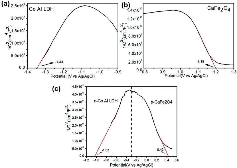
The VB and CB potentials regarding the conductivity type, reduction and oxidation level of the prepared semiconductors were calculated from electrochemical MS plots (Fig. 9) while the band gap energies were obtained from Tauc plots and were used to predict the mechanism of the photocatalytic reaction (Fig. S1†). Under solar light irradiation, the electrons shifted from the Au NPs to the surface of the composite automatically, progressing the formation of a rectifying contact at the Au NPs/LDH–CFO interface. The drift of electrons from noble metal NPs and the LDH–CFO surface was mainly dominated by the Schottky barriers originating from the difference in Fermi level of the Au NPs and the band structure of the nanocomposite.71
According to eqn (1), flat band potentials (Vfb) at the electrode–electrolyte interface were calculated via:
 | (1) |
5. Photocatalytic activity
5.1 Activity towards the water reduction and oxidation reaction
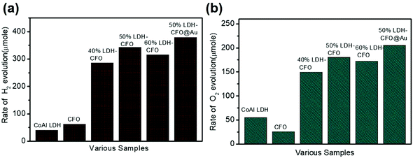
The photocatalytic activity of the LDH–CaFe2O4@Au hybrid was studied by performing the water splitting reaction for the evolution of H2 and O2. The photocatalytic water splitting reaction mainly involves two semi-reaction: a reduction half reaction and oxidation half reaction. In this study, we carried out two half reactions separately in the presence of a sacrificial electron donor (10% methanol solution) and a sacrificial electron acceptor (AgNO3 solution) for the series of prepared nano-hybrids. As shown in Fig. 10, all the photocatalysts promoted overall water splitting into H2 and O2 stoichiometrically with an approximate mole ratio (2![[thin space (1/6-em)]](https://www.rsc.org/images/entities/char_2009.gif) :
:![[thin space (1/6-em)]](https://www.rsc.org/images/entities/char_2009.gif) 1). Whereas in the case of pure LDH and CFO loaded with a single catalyst, a significantly lesser amount of gas H2 and O2 evolution was detected, which indicates a well-established redox reaction. However, the LDH–CaFe2O4@Au hybrid showed a satisfactory level of H2 evolution.
1). Whereas in the case of pure LDH and CFO loaded with a single catalyst, a significantly lesser amount of gas H2 and O2 evolution was detected, which indicates a well-established redox reaction. However, the LDH–CaFe2O4@Au hybrid showed a satisfactory level of H2 evolution.
Even though the band edge potential of Co Al LDH was suitable for the water reduction reaction, the result was not satisfactory. Fig. 10a compares the photocatalytic H2 evolution performance of all the synthesized samples along with the corresponding neat materials. CoAl LDH and CFO alone showed very low H2 evolution with 40.56 μmol h−1 and 62.2 μmol h−1, respectively. It was observed that ternary 50% LDH CFO@Au (379.1 μmol/2 h for 0.02 g of catalyst) showed superior photocatalytic hydrogen evolution, which was 1.10 times more than the 50% LDH–CFO catalyst (342 μmol/2 h for 0.02 g of catalyst) and 9.34 times more than pure LDH, confirming a positive effect of the better charge separation efficiency in the p–n junction. Moreover, the 50% LDH CFO@Au hybrid showed excellent stability towards H2 evolution (Fig. S5a†). The effect of Au on the activity of Au-loaded LDH and CFO was examined and is shown in Fig. S4a.† After Au loading, both LDH and CFO showed 1.67 and 1.54 times more H2 evolution than the neat counterparts, respectively. Table S1† compares the amount of H2 evolution between the recently published different LDH-modified nanocomposites with our prepared heterostructures and it could be observed that LDH–CFO@Au proved itself to be more efficient than the others.
Further taking the advantage of a suitable VB potential, the water oxidation performance of the hybrid photocatalyst was also studied. Compared to the water reduction reaction, the water oxidation involves a four-electron O2 evolution. When the reduction half reaction was completed, the oxidation half reaction was carried out using the same set of samples under the same light source in the presence of AgNO3 solution as an electron scavenger. The rate of O2 evolution for neat LDH and CFO were found to be 75.3 and 46.25 μmol h−1. The hybrid photocatalyst showed photocatalytic O2 evolution in the order of: 50%LDH–CFO@Au (205.5 μmol h−1) > 50%LDH–CFO (180.4 μmol h−1) > 60%LDH–CFO (172.5 μmol h−1) > 40%LDH–CFO (149.4 μmol h−1) > CoAl LDH (55.4 μmol h−1) > CFO(25.3 μmol h−1), as shown in Fig. 10b. Moreover, the evolution of O2 also increased 1.16 and 1.41 times after gold loading on LDH and CFO as compared to the neat materials, respectively (Fig. S4b†). Table S2† represents the amount of O2 evolution by the different LDH-modified nanocomposites, where it can be seen that the prepared heterostructures performed better than the other modified LDHs. The stability and reusability of the hybrid photocatalysts were investigated by performing the water oxidation reaction for five consecutive runs (Fig. S5b†). The 50% LDH CFO@Au hybrid showed excellent stability towards O2 evolution till 3rd run and then decreases slightly in the 4th and 5th runs.
5.2 Photocatalytic Cr(VI) reduction and kinetics
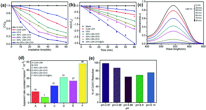
The photocatalytic activities of the synthesized samples for the reduction of hexavalent chromium were investigated under visible light to test the catalyst capability. The solution was stirred in the dark for 30 min before light expose to establish sorption equilibrium between the photocatalyst and Cr(VI) stock solution. We found that the catalyst Co Al LDH, CaFe2O4, 40% LDH–CFO, 50% LDH–CFO, 60% LDH–CFO and 50% LDH–CFO@Au showed adsorbtion of about 11.1%, 3.3%, 5.02%, 8.43%, 8.6% and 9.2% towards the Cr(IV) solution on the surface, respectively. Upon light irradiation, CFO-modified LDH showed better photocatalytic activity than the neat Co Al LDH and CaFe2O4, which was further enhanced with Au loading, as shown in Fig. 11a. Further, to support the photocatalytic performance, the TOF value for 50% LDH–CFO@Au was calculated and was found to be 0.0020834 s−1.75 This result was clearly in accordance with the lowest PL intensity, largest photocurrent density and reduced arc of the Nyquist plot. The rates of Cr(VI) reduction were in the order of: 50% LDH–CFO@Au > 50% LDH–CFO > 60% LDH-CFO > 40% LDH–CFO > Co Al LDH > CFO. The reduction of Cr(VI) also increased with gold loading on neat LDH and CFO, as shown in Fig. S4c.† Table S3† represents the comparison of Cr(VI) reduction over the heterostructure 50% LDH–CFO@Au with other reported materials. For the kinetics study, the rates of reduction were studied in 10 min time intervals. The spectral changes of absorbance for chromium removal using the best active catalyst LDH–CFO@Au is shown in Fig. 11c. Then the percentage of reduction was monitored for the kinetics study.It was observed that the photocatalytic Cr(VI) reduction followed first-order kinetics:
 | (2) |
The linear form of eqn (3) is represented as follows:
 | (3) |
As we know, concentration is directly related to the absorbance. The plot of ln(c/co) vs. time results in a straight line with slope k′, representing a first-order reaction, as shown in Fig. 11b. The apparent rate constant of all the synthesized samples for Cr(VI) reduction are represented in Table S4† and Fig. 11d. It was calculated that LDH–CFO@Au held a higher rate constant value 0.048 min−1, which was 3.4,6.8,2.2,1.5 and 1.7 times more than for Co Al LDH (0.014 min−1), CFO (0.007 min−1), 40% LDH–CFO (0.021 min−1), 50% LDH–CFO (0.031 min−1) and 60% LDH–CFO (0.01 min−1), respectively.
5.3 Effect of pH on photocatalytic Cr(VI) reduction
The surface charge of a catalyst plays an important role in adsorption and photocatalytic reduction. The pH of a solution always control the surface charge of the photocatalyst and influences the interfacial electron transfer. So to study the effect of pH, Cr(VI) reduction reaction was carried out in acidic, basic and neutral pHs. As shown in Fig. 11e, it was noticed that the reduction of Cr(VI) decreased with the increase in pH. At acidic pH (pH = 3.97), the composite revealed a maximum reduction as the photocatalyst surface becomes positive due to protonation and attracts the HCrO4− ions formed at lower pH. However at higher pH, the photocatalyst surface becomes negative and Cr species exist as Cr2O72−, experiencing a force of repulsion, thus hindering adsorption, which decreases the photocatalytic performance.76The stability of the photocatalyst was determined by comparing the structure of the 50% LDH–CFO@Au through XRD analysis before and after the photocatalytic Cr(VI) reduction. The XRD peaks at 2θ 11.7°, 23.6°, 34.6°, 60.3° and 61.7°, corresponding to 003, 006, 012, 011 and 0015 planes of Co Al LDH (JCPDS file No. 0045), and the diffraction patterns at 2θ = 33.4°, 33.6°, 35.5°, 25.5°, 19.2°, 40.3°, 46.4°, 49.7°, 61.3°, 50.4°, 19.2° and 71.6°, in accordance with JCPDS no. 00-019-0219, confirmed the presence of CFO nanoparticles with the same orthorhombic phase fitting to the space group pnam (S.G. 62), as shown in Fig. S6.† It was noticed that after Cr reduction, all the peaks due to the plane of LDH–CFO@Au remained almost the same with a slight decrease in intensity, which confirmed that the crystal structure and phase of the LDH–CFO@Au heterostructure remained intact after Cr reduction. Furthermore, the 50% LDH CFO@Au hybrid exhibited superb stability towards photocatalytic Cr reduction, as shown in Fig. S7.†
6. Proposed mechanism
From the results of photocatalytic H2/O2 evolution and Cr(VI) reduction, the prepared catalyst LDH–CFO@Au was ascertained to be a novel photocatalytic material. The LDH phase was attributed to play a leading role and its strong association with CFO further facilitated charge transport along with the improved photocatalytic behaviour of the catalyst. This improved photocatalytic activity is ascribed to the synergistic effect of the following factors(1) Large intimate contact surface due to p–n heterojunction
(2) Hot electron transfer concept
(3) Presence of Co as an oxidation catalyst.
In comparison to the photocatalytic activity of the neat Co Al LDH and CFO composite, the activity of the LDH–CFO hybrid heterostructure was found to be superior. This improved photocatalytic activity could be satisfactorily explained by calculating the band potential from the MS plot and the band gap energy (Eg) of the photoactive materials. The Evb positions of Co Al LDH and CFO were found to be 1.28 and 1.79 eV, while the Ecb position was found to be −0.74 and −0.14 eV, respectively. Whereas the LDH–CFO heterostructure presented an inverted V-shaped curve in the MS plot having two flat band potentials. The negative shift in the CB of the LDH–CFO heterostructure (1.01 eV vs. NHE) from the neat CFO (1.79 eV vs. NHE) and positive shift of the VB of the LDH–CFO heterostructure (−0.431 eV vs. NHE) from the neat Co Al LDH (−0.74 eV vs. NHE) signified the formation of a p–n junction with a higher degree of band bending (Fig. 9). As we know, along with the formation of the semiconductor heterojunction, there should be a band alignment to attain Fermi level equilibrium. The VB and CB potential of p-type and n-type semiconductors shift and get pinned up. For n and p-type semiconductors, the actual Fermi level is assumed to be 0.1 eV below the CB edge and 0.1 eV above the VB edge, respectively. The negative shift of the LDH–CFO heterostructure exerted a large space charge region for charge separation and for the positive shift, it consequently provides a strong driving force for the photogenerated charge pair separation. This results in the trapping of electron–hole pairs in the depletion layer due to the induced electric field at the p–n junction interface with enhanced photocatalytic activities. The presence of Co as an oxidation catalyst further influences the photocatalytic activity mainly due to two aspects:
(1) As discussed in the PL spectra, the d–d transition of Co+2 helps in promoting strong absorption in visible region. This distortion may produce a strong induced dipole moment and thus generates a strong local internal field to accelerate the separation of charge carriers.77
(2) In CoAl LDH, Co2+ was partly replaced by Al3+ in the Co (OH)2 lattice, maintaining the stable LDH structure by creating sheets by sharing edges between Co(II)O6 and Al(III)O6 octahedral units. In the case of CoO6, due to crystal field splitting, three 3d electrons of Co2+ occupy the t2g states and the two electrons occupy the eg states, having spin state S = 5/2. This spin splitting plays a vital role. The reductive site of Co(II) could trap the photogenerated charges and increase the charge separation.78 This is clearly evidenced from the PL spectra of the LDH, which becomes weaker after hybridization with CFO, significantly suppressing the electron–hole recombination, which is also further suppressed after Au loading.
Moreover, Au NPs also play a crucial role in enhancing the photocatalytic activity by a plasmon-mediated electron transfer (PMET) pathway. It is known from the hot electron photochemistry that the plasmon induced hot electron can directly transfer to the adjacent semiconductor photocatalyst by PMET79 According to Verma et al. and Warren et al., if the Au NPs have a particle size <20 nm, they will produce hot electrons.80–82 From the TEM image, as we confirmed the size of Au NPs (5–8 nm) are less than 20 nm, they are capable of producing hot electrons efficiently. Upon light irradiation, the Au-loaded LDH–CFO heterostructure, owing to its SPR effect, considerably increases the generation of hot electrons with high energy on the Au NPs and generates a fast and systematic transfer of these hot electrons to the semiconductor surface. The induced Schottky barrier at the interface of the Au NPs/semiconductor helps to trap the transferred hot electrons into the CB of both LDH and CFO in the heterostructure. This process helps to delay the hot electrons migrating back to the plasmonic metals.80,81
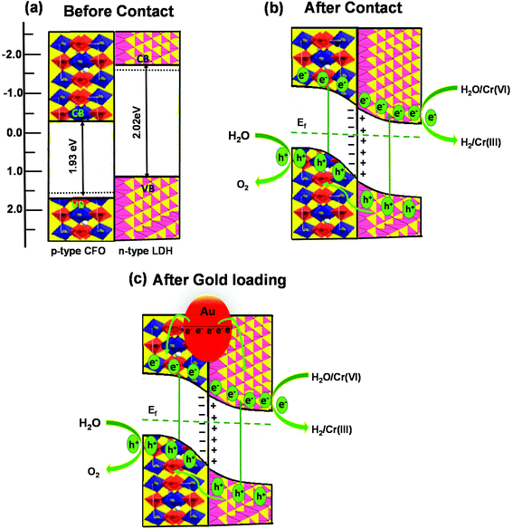
Based upon the above discussion, the possible band alignment between Co Al LDH and CFO before and after contact is schematically presented in Scheme 2, in which the mechanism for its superior photocatalytic activity over Co Al LDH–CFO is proposed. From the positions of the CB and VB of Co Al LDH and CFO, the formation may be explained by a type-II heterojunction before contact. As shown in Scheme 2a, the Fermi level of LDH lies higher than the Fermi level of CFO. But when they come in to contact, the electrons present in the higher fermi level of LDH will migrate towards the lower Fermi level of CFO till equilibration, as shown in Scheme 2b. When the equilibrium is reached between the Fermi level of n-type LDH and p-type CFO, a depletion layer is formed at the interface, as confirmed from the Mott–Schottky (MS) plots of LDH–CFO showing the formation of a p–n junction. Thus, upon light irradiation, the photoinduced electrons and holes are produced in their respective CB and VB positions and band bending takes place. So the photogenerated electrons from the CB of CFO are transferred to the lower positioned CB of Co Al LDH, and simultaneously a migration of holes take place from the lower VB potential of Co Al LDH to the higher VB potential CFO, as shown in Scheme 2b. The successful separation of electron and hole is possible due to the electric field formed in the depletion layer of the p–n junction. So water reduction and chromium reduction can take place on the LDH surface and water oxidation takes place on the CFO surface.
Recently noble metal Au loading has attracted wide interest to enhance the photocatalytic activity due to its surface plasmon effect and low photoluminescence intensity and reduced band gap. This is also proved by comparing the activity of 50% LDH–CFO and Au-loaded 50% LDH–CFO, whereby photocatalytic hydrogen evolution, oxygen evolution and chromium reduction increased by 1.29, 1.15 and 1.5 times more than the for the heterostructure 50% LDH–CFO. Similar observations were also reported by our group Patnaik et al., in which we modified the sulphated g-C3N4 by gold loading,83 while Sultana et al. prepared CeO2NS–Au–CdS,57 which enhanced the photocatalytic H2 evolution rate. Following the plasmon-mediated electron transfer (PMET) pathway, the hot electron transferred from Au NPs is easily trapped by the CB of LDH and CFO, making them capable of fostering the water splitting and chromium reduction, which was also confirmed by LSV study.
7. Conclusion
In summary, we developed a novel Au NPs-incorporated Co Al LDH/CFO p–n junction architecture, which could promote both water oxidation as well as reduction reaction with a high rate of H2 generation of 379.1 μmol h−1 in 10 vol% methanol, O2 evolution rate of 205.5 μmol h−1 in 0.05 M AgNO3 solution and also 99% Cr(VI) reduction in 1 h under visible light irradiation. The enhanced photocatalytic activity of the 50% LDH–CFO@Au p–n heterojunction was mainly attributed to multiple functions, like the formation of a heterojunction to promote charge transfer, co-catalyst activities for HER/OER and a plasmon-mediated hot electron transfer (PMET) pathway of Au NPs. These hot electrons are easily trapped by the CB of LDH/CFO, making them capable of fostering the water splitting reaction and Cr(VI) reduction, which was also confirmed by LSV study. The high photocatalytic activity could be attributed to the inner electric field created by the 50% LDH–CFO@Au p–n junction, providing spatial separation of charge and exhibiting a positive effect over thermodynamically preferred charge transport. Thereby, this work provides a novel strategy to design a durable and reusable 50% LDH–CFO@Au p–n junction-based architecture, which could be used as a promising photocatalyst for solar energy conversion.Conflicts of interest
There are no conflicts to declare.Acknowledgements
The authors are grateful to SOA university management for their support and encouragement.References
- W. Y. Teoh, J. A. Scott and R. Amal, J. Phys. Chem. Lett., 2012, 3, 629–639 CrossRef CAS.
- Q. Wang, T. Hisatomi, Y. Suzuki, Z. Pan, J. Seo, M. Katayama, T. Minegishi, H. Nishiyama, T. Takata, K. Seki and A. Kudo, J. Am. Chem. Soc., 2017, 139, 1675–1683 CrossRef CAS.
- X. Liu, X. Wang, H. Li, L. Pan, T. Lv, Z. Sun and C. Sun, J. Mater. Chem., 2012, 22, 16293–16298 RSC.
- F. E. Osterloh, Chem. Soc. Rev., 2013, 42, 2294–2320 RSC.
- T. F. Yeh, J. M. Syu, C. Cheng, T. H. Chang and H. Teng, Adv. Funct. Mater., 2010, 20, 2255–2262 CrossRef CAS.
- X. F. Gao, W. T. Sun, Z. D. Hu, G. Ai, Y. L. Zhang, S. Feng, F. Li and L. M. Peng, J. Phys. Chem. C, 2009, 113, 20481–20485 CrossRef CAS.
- B. Liu, X. Liu, J. Liu, C. Feng, Z. Li, C. Li, Y. Gong, L. Pan, S. Xu and C. Q. Sun, Appl. Catal., B, 2018, 226, 234–241 CrossRef CAS.
- M. G. Walter, E. L. Warren, J. R. McKone, S. W. Boettcher, Q. Mi, E. A. Santori and N. S. Lewis, Chem. Rev., 2010, 110, 6446–6473 CrossRef CAS.
- A. L. Linsebigler, G. Lu Jr. and J. T. Yates, Chem. Rev., 1995, 95, 735–758 CrossRef CAS.
- S. Lu, C. Li, H. H. Li, Y. F. Zhao, Y. Y. Gong, L. Y. Niu, X. J. Liu and T. Wang, Appl. Surf. Sci., 2017, 392, 966–974 CrossRef CAS.
- M. Shao, F. Ning, M. Wei, D. G. Evans and X. Duan, Adv. Funct. Mater., 2014, 24, 580–586 CrossRef CAS.
- C. G. Silva, Y. Bouizi, V. Fornés and H. García, J. Am. Chem. Soc., 2009, 131, 13833–13839 CrossRef.
- J. W. Boclair, P. S. Braterman, J. Jiang, S. Lou and F. Yarberry, Chem. Mater., 1999, 11, 303–307 CrossRef CAS.
- Y. Lee, J. H. Choi, H. J. Jeon, K. M. Choi, J. W. Lee and J. K. Kang, Energy Environ. Sci., 2011, 4, 914–920 RSC.
- S. Das, S. K. Dash and K. M. Parida, ACS Omega, 2018, 3, 2532–2545 CrossRef CAS.
- D. P. Sahoo, S. Nayak, K. H. Reddy, S. Martha and K. Parida, Inorg. Chem., 2018, 57, 3840–3854 CrossRef CAS.
- Y. Zhang, D. Du, X. Li, H. Sun, L. Li, P. Bai, W. Xing, Q. Xue and Z. Yan, ACS Appl. Mater. Interfaces, 2017, 9, 31699–31709 CrossRef CAS.
- M. Shao, F. Ning, M. Wei, D. G. Evans and X. Duan, Adv. Funct. Mater., 2014, 24, 580–586 CrossRef CAS.
- Y. Liu, N. Fu, G. Zhang, M. Xu, W. Lu, L. Zhou and H. Huang, Adv. Funct. Mater., 2017, 27, 1605307 CrossRef.
- L. Wang, H. Wang, W. Zhang, J. Zhang, J. P. Lewis, X. Meng and F. S. Xiao, J. Catal., 2013, 298, 186–197 CrossRef CAS.
- L. Mohapatra and K. Parida, J. Mater. Chem., 2016, 4, 10744–10766 RSC.
- Y. Zhao, X. Jia, G. I. Waterhouse, L. Z. Wu, C. H. Tung, D. O'Hare and T. Zhang, Adv. Energy Mater., 2016, 6, 1501974 CrossRef.
- D. P. Sahoo, S. Nayak, K. H. Reddy, S. Martha and K. Parida, Inorg. Chem., 2018, 57, 3840–3854 CrossRef CAS.
- S. Tonda, S. Kumar, M. Bhardwaj, P. Yadav and S. Ogale, ACS Appl. Mater. Interfaces, 2018, 10, 2667–2678 CrossRef CAS.
- J. Ni, J. Xue, L. Xie, J. Shen, G. He and H. Chen, Phys. Chem. Chem. Phys., 2018, 20, 414–421 RSC.
- Z. Wang, Y. Song, J. Zou, L. Li, Y. Yu and L. Wu, Catal. Sci. Technol., 2018, 8, 268–275 RSC.
- Y. Zhu, R. Zhu, G. Zhu, M. Wang, Y. Chen, J. Zhu, Y. Xi and H. He, Appl. Surf. Sci., 2018, 433, 458–467 CrossRef CAS.
- S. Iguchi, Y. Hasegawa, K. Teramura, S. Kidera, S. Kikkawa, S. Hosokawa, H. Asakura and T. Tanaka, Sustainable Energy Fuels, 2017, 1, 1740–1747 RSC.
- S. Nayak, L. Mohapatra and K. Parida, J. Mater. Chem. A, 2015, 3, 18622–18635 RSC.
- S. Nayak and K. M. Parida, Int. J. Hydrogen Energy, 2016, 41, 21166–21180 CrossRef CAS.
- S. Acharya and K. Parida, ChemistrySelect, 2017, 2, 10239–10248 CrossRef CAS.
- S. Nayak and K. M. Parida, ACS Omega, 2018, 3, 7324–7343 CrossRef CAS.
- D. P. Sahoo, S. Patnaik, D. Rath and K. M. Parida, Inorg. Chem. Front., 2018, 5, 879–896 RSC.
- H. G. Kim, P. H. Borse, J. S. Jang, E. D. Jeong, O. S. Jung, Y. J. Suh and J. S. Lee, Chem. Commun., 2009, 5889–5891 RSC.
- C. Shifu, Z. Wei, L. Wei, Z. Huaye, Y. Xiaoling and C. Yinghao, J. Hazard. Mater., 2009, 172, 1415–1423 CrossRef.
- P. Li, P. P. Huang, F. F. Wei, Y. B. Sun, C. Y. Cao and W. G. Song, J. Mater. Chem. A, 2014, 2, 12739–12745 RSC.
- Y. Zhu, J. Rong, T. Zhang, J. Xu, Y. Dai and F. Qiu, ACS Appl. Nano Mater., 2017, 1, 284–292 CrossRef.
- G. Fan, Z. Gu, L. Yang and F. Li, Chem. Eng. J., 2009, 155, 534–541 CrossRef CAS.
- E. S. Kim, N. Nishimura, G. Magesh, J. Y. Kim, J. W. Jang, H. Jun, J. Kubota, K. Domen and J. S. Lee, J. Am. Chem. Soc., 2013, 135, 5375–5383 CrossRef CAS.
- X. Yang, V. Salles, Y. V. Kaneti, M. Liu, M. Maillard, C. Journet, X. Jiang and A. Brioude, Sens. Actuators, B, 2015, 220, 1112–1119 CrossRef CAS.
- Y. Zhu, R. Zhu, G. Zhu, M. Wang, Y. Chen, J. Zhu, Y. Xi and H. He, Appl. Surf. Sci., 2018, 433, 458–467 CrossRef CAS.
- L. Chen, B. Sun, X. Wang, F. Qiao and S. Ai, J. Mater. Chem. B, 2013, 1, 2268–2274 RSC.
- S. Vadivel, D. Maruthamani, A. Habibi-Yangjeh, B. Paul, S. S. Dhar and K. Selvam, J. Colloid Interface sci., 2016, 480, 126–136 CrossRef CAS PubMed.
- D. Chen, F. Zhang, Q. Li, W. Wang, G. Qian, Y. Jin and Z. Xu, Int. J. Hydrogen Energy, 2017, 42, 867–875 CrossRef CAS.
- H. Li, F. Yue, H. Xie, C. Yang, Y. Zhang, L. Zhang and J. Wang, CrystEngComm, 2018, 20, 889–895 RSC.
- R. Jin, Y. Ma, Y. Sun, H. Li, Q. Wang and G. Chen, Energy Technol., 2017, 5, 293–299 CrossRef CAS.
- M. D. Detwiler, A. Gharachorlou, L. Mayr, X. K. Gu, B. Liu, J. Greeley, W. N. Delgass, F. H. Ribeiro and D. Y. Zemlyanov, J. Phys. Chem. C, 2015, 119, 2399–2411 CAS.
- B. M. Reddy, B. Chowdhury, E. P. Reddy and A. Fernández, Appl. Catal., A, 2001, 213, 279–288 CrossRef CAS.
- P. Dolcet, A. Mambrini, M. Pedroni, A. Speghini, S. Gialanella, M. Casarin and S. Gross, RSC Adv., 2015, 5, 16302–16310 RSC.
- H. Song, S. Oh, H. Yoon, K. H. Kim, S. Ryu and J. Oh, Nano Energy, 2017, 42, 1–7 CrossRef CAS.
- S. L. Stipp Jr. and M. F. Hochella, Geochim. Cosmochim. Acta, 1991, 55, 1723–1736 CrossRef.
- X. Cai, L. Mao, S. Yang, K. Han and J. Zhang, ACS Energy Lett., 2018, 3, 932–939 CrossRef CAS.
- T. H. Yang, L. D. Huang, Y. W. Harn, C. C. Lin, J. K. Chang, C. I. Wu and J. M. Wu, Small, 2013, 9, 3169–3182 CrossRef CAS.
- J. F. Moulder, W. F. Stickle, P. E. Sobol, K. D. Bomben and J. Chastian, in Handbook of X-Ray Photoelectron Spectroscopy, ed. J. Chastian, Perkin-Elmer, Eden Prairie, MN, 1992 Search PubMed.
- T. Wang, B. Jin, Z. Jiao, G. Lu, J. Ye and Y. Bi, J. Mater. Chem. A, 2014, 2, 15553–15559 RSC.
- M. Ahmad, S. Yingying, A. Nisar, H. Sun, W. Shen, M. Wei and J. Zhu, J. Mater. Chem., 2011, 21, 7723–7729 RSC.
- S. Sultana, S. Mansingh, M. Scurrell and K. M. Parida, Inorg. Chem., 2017, 56, 12297–12307 CrossRef CAS.
- D. E. Jiang, S. H. Overbury and S. Dai, J. Phys. Chem. Lett., 2011, 2, 1211–1215 CrossRef CAS.
- L. Mohapatra and K. M. Parida, Phys. Chem. Chem. Phys., 2014, 16, 16985–16996 RSC.
- P. F. Liu, S. Yang, B. Zhang and H. G. Yang, ACS Appl. Mater. Interfaces, 2016, 8, 34474–34481 CrossRef CAS.
- K. Das, S. N. Sharma, M. Kumar and S. K. De, J. Phys Chem. C, 2009, 113, 14783–14792 CrossRef CAS.
- S. Kumar, K. Asokan, R. K. Singh, S. Chatterjee, D. Kanjilal and A. K. Ghosh, RSC Adv., 2014, 4, 62123–62131 RSC.
- M. Crivello, C. Pérez, E. Herrero, G. Ghione, S. Casuscelli and E. Rodríguez-Castellón, Catal. Today, 2005, 107, 215–222 CrossRef.
- M. J. Holgado, V. Rives and M. S. San Román, Appl. Catal., A, 2001, 214, 219–228 CrossRef CAS.
- L. Y. Mostovaya, T. S. Petkevich and L. A. Kupcha, J. Appl. Spectrosc., 1989, 51, 1298–1301 CrossRef.
- C. Rudolf, B. Dragoi, A. Ungureanu, A. Chirieac, S. Royer, A. Nastro and E. Dumitriu, Catal. Sci. Technol., 2014, 4, 179–189 RSC.
- S. Kumar, M. A. Isaacs, R. Trofimovaite, L. Durndell, C. M. Parlett, R. E. Douthwaite, B. Coulson, M. C. Cockett, K. Wilson and A. F. Lee, Appl. Catal., B, 2017, 209, 394–404 CrossRef CAS.
- S. Ida, K. Yamada, T. Matsunaga, H. Hagiwara, Y. Matsumoto and T. Ishihara, J. Am. Chem. Soc., 2010, 132, 17343–17345 CrossRef CAS.
- Y. Zhu, R. Zhu, G. Zhu, M. Wang, Y. Chen, J. Zhu, Y. Xi and H. He, Appl. Surf. Sci., 2018, 433, 458–467 CrossRef CAS.
- Y. Wang, J. Yu, W. Xiao and Q. Li, J. Mater. Chem. A, 2014, 2, 3847–3855 RSC.
- M. R. Khan, T. W. Chuan, A. Yousuf, M. N. Chowdhury and C. K. Cheng, Catal. Sci. Technol., 2015, 5, 2522–2531 RSC.
- Y. Hou, X. Y. Li, Q. D. Zhao, X. Quan and G. H. Chen, Adv. Funct. Mater., 2010, 20, 2165–2174 CrossRef CAS.
- H. M. Kim, T. W. Kang and K. S. Chung, Adv. Mater., 2003, 15, 567–569 CrossRef CAS.
- K. H. Reddy, K. Parida and P. K. Satapathy, J. Mater. Chem. A, 2017, 5, 20359–20373 RSC.
- I. U. Din, M. S. Shaharun, D. Subbarao and A. Naeem, J. Power Sources, 2015, 274, 619–628 CrossRef.
- D. K. Padhi and K. Parida, J. Mater. Chem. A, 2014, 2, 10300–10312 RSC.
- Y. Zhang, J. Shi, Y. Hu, Z. Huang and L. Guo, Catal. Sci. Technol., 2016, 6, 8080–8088 RSC.
- Y. Xu, A. Li, T. Yao, C. Ma, X. Zhang, J. H. Shah and H. Han, ChemSusChem, 2017, 10, 4277–4305 CrossRef CAS.
- Y. Zhang, S. He, W. Guo, Y. Hu, J. Huang, J. R. Mulcahy and W. D. Wei, Chem. Rev., 2017, 118, 2927–2954 CrossRef.
- S. C. Warren and E. Thimsen, Energy Environ. Sci., 2012, 5, 5133–5146 RSC.
- K. Wu, W. E. Rodríguez-Córdoba, Y. Yang and T. Lian, Nano Lett., 2013, 13(11), 5255–5263 CrossRef CAS PubMed.
- A. Verma, A. Srivastav, S. A. Khan, V. R. Satsangi, R. Shrivastav, D. K. Avasthi and S. Dass, Phys. Chem. Chem. Phys., 2017, 19, 15039–15049 RSC.
- S. Patnaik, S. Martha, G. Madras and K. Parida, Phys. Chem. Chem. Phys., 2016, 18, 28502–28514 RSC.
Footnote |
| † Electronic supplementary information (ESI) available: Band gap energy of neat Co Al LDH, CFO, 50% LDH–CFO and 50% LDH–CFO@Au. H2 and O2 production study of LDH–CFO@Au heterostructure using various scavenger components. Cycling test for H2 andO2 evolution of LDH–CFO@ Au. XRD plot of 50% LDH–CFO before and after photocatalytic reaction. Comparison table for H2 and O2 evolution with different LDH-modified nanocomposites. Rate of Cr(VI) reduction over 50% LDH–CFO@ Au heterostructure with other reported materials. Regression co-efficient (R2) and rate constant (k) values of the synthesized samples in Cr(VI) reduction. See DOI: 10.1039/c8qi00952j |
| This journal is © the Partner Organisations 2019 |

