
Photochromic control of a plasmon–quantum dots coupled system†
Gwénaëlle
Lamri
a,
Artur
Movsesyan
 a,
Edite
Figueiras
b,
Jana B.
Nieder
b,
Jean
Aubard
c,
Pierre-Michel
Adam
a,
Christophe
Couteau
a,
Nordin
Felidj
c and
Anne-Laure
Baudrion
*a
a,
Edite
Figueiras
b,
Jana B.
Nieder
b,
Jean
Aubard
c,
Pierre-Michel
Adam
a,
Christophe
Couteau
a,
Nordin
Felidj
c and
Anne-Laure
Baudrion
*a
aLumière, nanomatériaux et nanotechnologies (L2n), Institut Charles Delaunay, CNRS, Université de Technologie de Troyes, 12 rue Marie Curie, CS 42060, 10004 Troyes Cedex, France. E-mail: anne_laure.baudrion@utt.fr
bQuantaLab, Ultrafast Bio- and Nanophotonics Group, INL – International Iberian Nanotechnology Laboratory, Av. Mestre José Veiga, 4715-310 Braga, Portugal
cLaboratoire Interfaces, Traitements, Organisation et Dynamique des Systèmes (ITODYS), UMR CNRS 7086, Université Paris-Diderot, Sorbonne Paris Cité, 15 rue Jean-Antoine de Baïf, 75205 Paris Cedex 13, France
First published on 19th November 2018
Abstract
The control of quantum dot (QD) photoluminescence (PL) is a challenge for many applications. It is well known that plasmonic resonances can enhance this PL. In this work, we couple QDs with silver nanoparticles and immerse the system in a photochromic organic material. As these molecules are optical switches going from a transparent to a colored isomer by absorbing UV light, we observe on one hand a Förster Resonant Energy Transfer (FRET) between the QD emission and the absorbing isomer and on the other hand a plasmonic PL enhancement. The photochromic transition leads to the optical control of the FRET, allowing us to control the QD de-excitation preferences (radiative or non-radiative) and so the emitted light.
Introduction
Quantum dots (QDs), also named semiconductor nanocrystals, present a unique set of optical properties, which occur from a quantum confinement effect.1–3 Indeed, QDs can present bright photoluminescence (PL) which depends on the nanocrystal size and composition,4,5 a broad absorption spectrum with a large crosssection,6,7 a large effective Stokes shift (up to hundreds of nanometers), a spectrally narrow and symmetric PL emission and good resistance to photobleaching.8 All these properties allow for the QDs to be widely used in applications: as markers in bio-imaging processes,9 in the development of new LEDs10 or as single photon sources in the emerging field of quantum nanooptics.11 For these applications, the external modulation of the QD's PL would be of prime interest.A way to modulate the QD's luminescence is to combine them with chromophores. Indeed, by a Förster resonance energy transfer (FRET) process, a donor fluorophore can transfer its energy to an acceptor chromophore. The energy transfer is non-radiative, i.e. occurring without the involvement of photons.12 The QDs can be used as acceptors13 but are more generally used as donors with dyes as acceptors.14 Interesting dyes are those which exhibit photochromism properties.15,16 Indeed, due to their ability to optically switch between two molecular states with different absorption properties, the photochromic molecules (PM) have been used to actively control the QD's PL.17 As this modulation is based on an energy transfer from the QD, the PL can never reach a higher intensity than the one emitted by the QD alone. However, it has been proven that the PL intensity can be enhanced by coupling the QDs to plasmonic nanoparticles (NPs), like metallic nanoparticles,18,19 nanopockets20 or nanoantennas.21 By taking advantage of the localized surface plasmon resonance (LSPR), this coupling can influence three major parameters,22 which are the collection efficiency (the number of photons collected by the setup), the QD's excitation efficiency (or how one photon can create an exciton) and the emitter's quantum yield (defined as the ratio between the radiative decay rate ΓR and the total decay rate Γ, sum of the radiative and the non-radiative decay rates). Actually, the coupling between a QD and a metallic nanoantenna can lead to two major phenomena: either the effective quantum yield increases and we observe an enhancement of the emitted PL or the quantum yield decreases and we observe a quenching of the emitted PL. This depends on the ratio between the modifications of the radiative and the non-radiative decay rates of the emitter.23–25 In this letter, we report on the optical control of the de-excitation pathways of a coupled system between CdSe/ZnS QDs and silver nanocylinders using the conformational change of photochromic spiropyran molecules. To our knowledge, it is the first time that these three components are combined. This work could be a first step towards the all-optical-control of the QD's photoluminescence.
Experimental details
We use standard e-beam lithography to fabricate eleven arrays of silver cylindrical NPs, with varying diameters from 60 nm to 160 nm, in steps of 10 nm. In each array, the nanocylinders are randomly distributed (see Fig. S1a of the ESI†) in order to avoid diffraction and grating effects during the optical measurements. After the e-beam process, we deposited by thermal evaporation a 5 nm-thick silica layer on top of the nanoparticles to protect the silver from oxidation. We deposited onto the SiO2 layer a 1 wt% polymethylmethacrylate (PMMA) solution containing QDs and PM diluted in toluene in order to achieve a thickness of about 20 nm. The QDs are CdSe/ZnS core–shell nanocrystals, emitting at 510 nm and purchased from Mesolight, Inc. The PM used is 1′,3′,3′-trimethyl-6-nitrospiro(2H-1-benzopyran-2,2′-(2H)-indole), purchased from Sigma-Aldrich® and referred as 6-nitro-BIPS in the literature.26 In the following, we will name the photochromic molecule “SP” in its uncolored spiropyran form and “MC” in its photo-activated merocyanine colored form.27 The photochromic conversion is activated by shining UV light onto the sample for one minute. After the photochromic transition, the MC isomer displays an absorption peak centered at 570 nm![[thin space (1/6-em)]](https://www.rsc.org/images/entities/char_2009.gif) 28 and it is accompanied by a refractive index variation up to 0.25 (see section 2 of the ESI†). Fig. 1a and b show detailed schemes of the sample before and after the photochromic transition, respectively. In the following, to understand the three entity system, we will characterize the interactions between the couples of the entities, i.e. NPs-PM, QDs-NPs and QDs-PM.
28 and it is accompanied by a refractive index variation up to 0.25 (see section 2 of the ESI†). Fig. 1a and b show detailed schemes of the sample before and after the photochromic transition, respectively. In the following, to understand the three entity system, we will characterize the interactions between the couples of the entities, i.e. NPs-PM, QDs-NPs and QDs-PM.
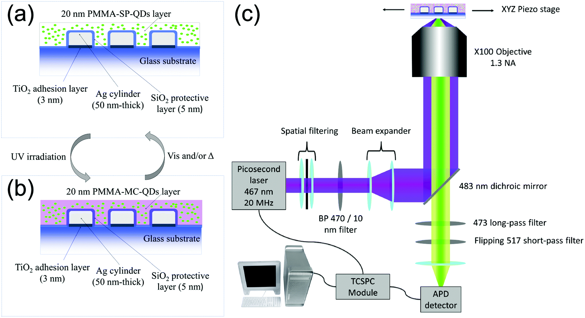 | ||
| Fig. 1 Schemes of the sample in (a) spiropyran (SP) and (b) merocyanine (MC) isomers. (c) Scheme of the custom-built FLIM microscope. | ||
It is well known that the coupling between the NPs, plasmonic resonances and emitters can lead to a strong coupling phenomenon.29 This behavior is observed by the appearance of a dip in the plasmonic and the emission spectra, explained by a band gap between two new strongly coupled modes. This has been evidenced between the LSPR and the excited state of merocyanine molecules30 and also between the LSPR and QDs at room temperature.31,32 To study this coupling, we measured the plasmonic resonances for different NP diameters, with an extinction micro-spectrometer before and after the photochromic transition by the following the process described in ref. 30 (see the extinction spectra in Fig. S3 of the ESI†). Even for the plasmonic resonances which coincide with the MC absorption band (570 nm), we do not notice any influence of the photochromic transition on the plasmonic system. We can then conclude that the 5 nm-thick silica layer covering the NPs avoids any coupling (strong or weak) between the plasmonic resonance and the PM molecular exciton. As a strong coupling regime between the QDs and the LSPR requires, among others, a very short coupling distance between the entities,31,32 we can assume that the silica layer avoids any strong coupling regime between the QDs and the LSPR.
A custom-built confocal microscope (Fig. 1c) was used as a fluorescence lifetime image microscope (FLIM) to record the PL intensity and PL lifetime images, by scanning the sample across the focus of a 467 nm picosecond pulsed excitation laser. The collected signal is filtered around the QD's emission (473–517 nm) and for each scan pixel, the time-correlated single photon counting (TCSPC) system is used to record the QD's fluorescence decay curve.33 The PL intensity is then deduced by integrating the photon counts over the detection time window and the fluorescence lifetime is obtained by a weighted average of a multi-exponential fit of the decay curve. The detailed description of the setup can be found in section 4 of the ESI.†
Results and discussion
Fig. 2 shows the PL intensity images recorded before (a) and after (b) the photochromic transition. The silver NP arrays are clearly identified by the squared areas presenting modified fluorescence intensities. To help the identification of these areas, they were labeled with their respective nanocylinder diameters. The nanocylinder arrays with the diameters of 80 nm and 130 nm have been recorded during a second scan and the images have been stitched as shown in Fig. 2. We observe that, in the SP isomer (see Fig. 2a), the QD's PL is drastically reduced on NP arrays, when compared to that on the NPs located in the surrounding areas (called background henceforth). It suggests that the presence of the NPs leads to the quenching of the PL. It is important to note that this quenching has been observed in the absence of photochromic molecules (see Fig. S4 of the ESI†). Indeed, even if the silica layer is supposed to avoid a non-radiative energy transfer to the metal, the plasmonic resonance does not lead to any enhancement of the PL. We suppose it is due to the high quantum yield of our QDs (known to be higher than 70% in a PMMA matrix34), which probably do not allow any enhancement effect. After the photochromic transition, the photoluminescence of the QDs in the MC isomer is enhanced on the arrays compared to that in the background (Fig. 2b). Moreover, the QD PL seems to be maximal on the 70 nm-diameter NP array when embedded in the MC isomer. This contrast inversion has to be balanced by the quantitative analysis of the PL intensity. Indeed, we observe that the QD's PL intensity in the background areas decreases from 2500 counts in SP to 400 counts in MC, indicating that the photochromic transition reduces the QDs’ emission itself by about 80%. In contrast, on the 70 nm-diameter NP array, the PL intensity decreases from 1300 counts in SP to about 700 counts in MC, indicating a reduction of only 45%. This observation leads us to think that the plasmonic resonance counter-balances the effect of the photochromic transition on the QDs’ emission. The physical phenomena explaining this observation will be discussed in the following.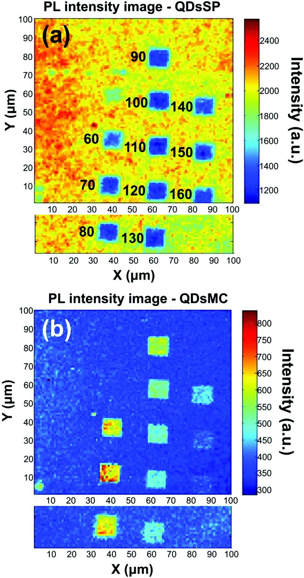 | ||
| Fig. 2 Photoluminescence images recorded on the silver nanoparticle ensembles covered with QDs and spiropyran molecules, before (a) and after (b) the photochromic transition. For each image, two scans have been recorded and the resulting image has been obtained with a stitching process. In image (a) are written the diameters of the nanocylinders. | ||
Firstly, to retrieve the influence of the NPs on the QD emission in each separate PM form, we plot the normalized PL, also called the enhancement factor in the literature,22 as a function of the NP diameter (Fig. 3a). The red dashed and the green solid curves are related to the QD emission embedded in the SP and MC isomers, respectively. For each curve, the mean PL intensity recorded on the array's area (about 20 × 20 μm) is divided by the mean PL intensity recorded in the background area (considering approximately the same surface area). A PL enhancement ηF is then defined by ηF > 1 and the PL quenching is deduced by ηF < 1. We thus observe that the PL is quenched when QDs are coupled with NPs in the SP isomer (dashed red curve) and that the NP diameter has no significant influence on the normalized PL value. From the green curve, related to the MC isomer, we can deduce that there is an enhancement for all NP cylinder sizes and a maximum enhancement for nanocylinders with a diameter of 70 nm. This behavior in the MC state, is a signature of a coupling between the LSPR and the QD excited state. Indeed, it is well known that the coupling between the QDs and the NPs is higher when the plasmonic resonance coincides with the QD absorption and/or emission.35 In Fig. 3b, we plot as a function of the particle diameter, the overlap integral between the QD PL emission and the measured plasmonic extinction spectra of the nanocylinders (see the inset of Fig. 3b). This curve shows which NP diameter presents a LSPR fitting with the QD emission. Moreover, in Fig. 3c, we plot the plasmonic extinction value recorded at 467 nm (i.e. the QD excitation wavelength) as the function of the particle diameter (see the inset of Fig. 3c). This curve shows which NP diameter presents a LSPR fitting with the QD excitation. Both Fig. 3b and c show that the 70 to 80 nm-diameter NPs should lead to a maximum coupling between the NPs and the QDs, which agrees with what we observe in the PL intensity image of Fig. 2b. We conclude that the coupling between the QDs and the 70 nm-diameter NPs is efficient and leads to PL quenching in the case of QDs embedded in the SP isomer, whereas it leads to a PL enhancement of QDs embedded in the MC isomer.
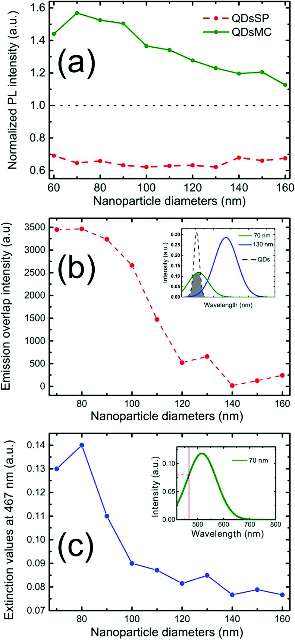 | ||
| Fig. 3 (a) Enhancement factor of the PL recorded on the silver nanocylinders, before (dashed red curve) and after (green curve) the photochromic transition as a function of their diameter. (b) Emission overlap intensity between the QD spectrum and the plasmonic resonance spectra of the silver nanoparticles. (c) Plasmonic extinction values at 467 nm. | ||
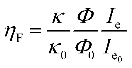
To analyze the different emission efficiencies of the QDs in dependence of the PM state, we analyze the effects influencing the luminescence enhancement factor ηF, which is usually defined as:22
 | (1) |
In the SP isomer, the PL of the QDs recorded on the NP arrays seems independent of the NPs diameter (see Fig. 2a and 3a). To understand this behavior, we record the FLIM image (which is related to the QD's lifetime) before and after the photochromic transition (Fig. 4a and b). Before photoactivation, the QD emission displays a lifetime of about 6.1 ns outside the NP arrays, whereas on the nanoparticle arrays, the lifetime is reduced to around 2 ns. Once again, the 70 nm diameter-NPs present the strongest fluorescence lifetime reduction, indicating a resonant coupling with the LSPR of the nanocylinders. After the photochromic transition (Fig. 4b), one can observe that the emission lifetime outside the NP functionalized arrays dropped to 1.3 ns, while the emission lifetime on top of the NP areas is even shorter with values of about 1 ns. The reduction of the QD fluorescence lifetime in NP-free areas (from 6,1 to 1,3 ns) and the 80% decrease of the PL intensity in these regions through the photochromic transition (see Fig. 2a and b) can be the result of a FRET effect36 and shall be discussed.
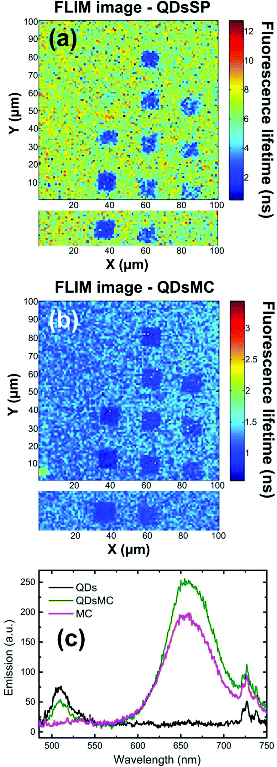 | ||
| Fig. 4 FLIM images recorded on silver nanocylinder arrays covered with a layer of QDs and spiropyran molecules, before (a) and after (b) the photochromic transition. For each image, two scans have been recorded and the resulting image has been obtained by a stitching process. (c) Emission spectra recorded with a layer of QDs in PMMA (black curve), with a layer of the MC isomer (purple curve) and for a layer of QDs + MC (green curve) illustrating the FRET effect between both entities. | ||
Indeed, the broad (about 150 nm FWHM) MC absorption spectrum displays a maximum at 570 nm and overlaps the emission spectrum of the QDs.30 Moreover, the MC isomer emits weak fluorescence at 650 nm,37 which is filtered out in our experiment. To prove a possible FRET effect between the QDs and MC, we recorded the PL spectra of glass substrates covered with a PMMA layer containing either QDs, MC molecules, or a QDs-MC mixture (Fig. 4c). For these experiments, we use a standard upright fluorescence microscope with a xenon lamp, filtered with a 465/5 nm band pass filter. A 485 nm dichroic mirror was used to reflect the lamp excitation, while the fluorescence was collected through a 480 nm long pass filter and sent to the fiber-coupled spectrometer. The QDs emit at 510 nm (black curve) whereas the MC molecules emit at 650 nm (red curve). When QDs are in the presence of MC isomers (green curve), it is observed that the QD emission decreases while the MC emission increases, indicating an energy transfer between the two species. Using the FRET model, we determine a FRET efficiency of around 79%, which shows that the energy transfer between the QD and the MC isomers is very efficient (calculations are detailed in section 5 of the ESI†).
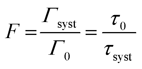
To be able to compare our experimental results with FDTD simulations, we first convert the enhancement factors in measures of the Purcell factor. The Purcell factor F, is defined as the ratio between the total decay rate of the coupled system Γsyst and the total decay rate of the uncoupled emitter entity Γ0:38
 | (2) |
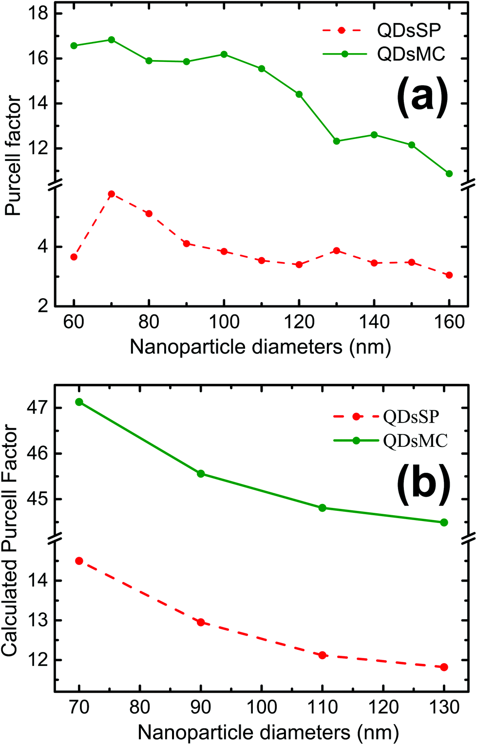 | ||
| Fig. 5 (a) Experimentally derived Purcell factor over silver nanocylinder diameters. (b) Calculated Purcell factor for nanoparticle diameters of 70 nm, 90 nm, 110 nm and 130 nm in the SP isomer (red dashed curve) and in the MC isomer (green curve). | ||
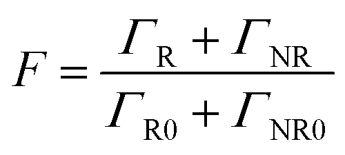
The Purcell factor can also be expressed in terms of the total decay rate, which is the sum of the radiative ΓR and non-radiative ΓNR decay rates, it follows:
 | (3) |
The coupling between the QDs and SP leads obviously to the quenching of the PL, probably due to a dominant increase of the non-radiative decay rate ΓNR. After the photochromic transition, the Purcell factor increases for the QD in the MC isomer, compared to the one in the SP isomer. This means that the total decay rate of the QDs–NPs coupled system increases during the photochromic transition from SP to MC.
As a FRET effect increases the non-radiative decay rate and additionally FRET effect can be enhanced by resonant NPs,40 the net ΓNR is increased for QDs embedded in the MC isomer compared to the SP isomer. The description of the net effect for the radiative decay rate modification is more complicated, but we can expect an overall increase of the ΓR as the 5 nm silica layer largely prevents the QDs from residing at <5 nm short distances to the NPs, which are often associated with short fluorescence quenching distances.
We then use the Finite Difference Time Domain (FDTD) method (FDTD software, Lumerical Inc.) to calculate the Purcell factor for our system. For this purpose, we model a silver nanocylinder covered with a 5 nm silica layer. The PM layer is simulated by a layer with a varying refractive index, taken from ellipsometric measurements.30 A perfect emitting dipole (quantum yield of one) is placed at 7.5 nm on top of the nanocylinder. This value is reasonable considering the 5 nm thick silica layer and the spin-coated 20 nm thick PM- and QD-doped PMMA layer. Indeed, it is known that the spin-coat will reduce the thickness of the PM layer on top of the topological defects, such as the NPs.41 The results of the simulations are presented in Fig. 5b.
The Purcell factor, defined by eqn (3), has been averaged for three spatial orientations of the dipole and the calculation has been performed for four NP diameters in the SP isomer (red dashed curve) and in the MC isomer (green curve). In analogy with our experimental results, we obtain a three times higher Purcell factor in the MC isomer than in the SP isomer. The Purcell factor furthermore decreases for larger NP diameters, confirming our experimental observations. We have to note that the trend is the same but the absolute values are different due to the average.
To summarize, for the QD–NP coupled system consisting of CdSe/ZnS core–shell nanocrystals and 70 nm-diameter nanocylinders, our study reveals that the photochromic transition of the surrounding 6-nitro-BIPS molecules: (i) does not impact the plasmonic resonance of the NPs, (ii) can trigger a FRET transfer increasing the non-radiative decay of the QD exciton, and (iii) enhances the quantum yield of the QD–NP coupled system by promoting the radiative de-excitation of the QD exciton through the plasmonic particle. Therefore, for resonant NPs covered with the MC isomer, we clearly observe a competition between a FRET effect and a plasmonic enhancement of the QD's PL. Since the QDs present a high quantum yield in the SP isomer, the plasmonic coupling leads to the PL quenching. After the photochromic transition, the FRET effect leads to a decrease of the quantum yield, giving then the opportunity for a plasmonic enhancement to take place. We can conclude that the photochromic transition is responsible for a de-excitation pathway inversion for the QD exciton. A possible explanation can come from the refractive index modification induced by the UV-illumination. Indeed, we showed that the photoactivated switch from SP to MC is accompanied by a negative change of the refractive index for wavelengths below 570 nm (see the ESI†). Such a negative variation of the homogeneous medium surrounding a QD is typically accompanied by a decrease of the accessible LDOS and so the intrinsic QD radiative decay rate decreases.42 In this case, we suppose that the QD emits in the higher LDOS, here provided by the plasmonic resonance.
Conclusions
In this letter, we demonstrated that the photochromic transition allows the optical control of the de-excitation pathways of a QD/NP coupled system, thus permitting the driving of the photoluminescence from quenching to enhancement. These considerations led us to expect that this three-entity system should be of high interest for QDs presenting a low quantum yield. In that case, the plasmonic enhancement should take place in the transparent isomer and the FRET could lead to an extinction of the QD's PL. These results consist in a significant advance in the active control of the QD's photoluminescence and could be considered for innovative lighting or display technologies.Funding
The authors acknowledge the financial support from the “Conseil Régional Champagne-Ardenne” and the “Fonds Européen de Développement Régional (FEDER) fund” through a Ph.D fellowship. Edite Figueiras acknowledges an EC COFUND Marie Curie fellowship (grant no. 600375) and Jana B. Nieder acknowledges the support from CCDR-N via the project (grant no.: NORTE-01-0145-FEDER-000019). This work has been carried out in the framework of the Cost Action MP1302 Nanospectroscopy and finally, the authors thank the technical support from the Nano'Mat platform (http://www.nanomat.eu).Conflicts of interest
There are no conflicts of interest to declare.Acknowledgements
The authors acknowledge Serguei KOSTCHEEV for the macro on the lithography design software, Ricardo ADÃO for providing MATLAB-integrated FLIM analysis software and Loïc LE CUNFF for the data processing.References
- H. Hartmut and S. W. Koch, Quantum Theory of the optical and electronic properties of semiconductors, World Scientific Collection, 2009 Search PubMed.
- D. Miller, D. S. Chemla, T. C. Damen, A. C. Gossard, W. Wiegmann, T. H. Wood and C. A. Burrus, Phys. Rev. B: Condens. Matter Mater. Phys., 1985, 32, 1043 CrossRef CAS.
- S. Schmitt-Rink, D. A. B. Miller and D. S. Chemla, Phys. Rev. B, 1987, 35, 8113 CrossRef CAS.
- D. J. Norris and M. G. Bawendi, Phys. Rev. B: Condens. Matter Mater. Phys., 1996, 53, 16338 CrossRef CAS.
- I. Moreels, K. Lambert, D. Smeets, D. De Muynck, T. Nollet, J. C. Martins, F. Vanhaecke, A. Vantomme, C. Delarue, G. Allan and Z. Hens, ACS Nano, 2009, 3, 3023 CrossRef CAS PubMed.
- C. A. Leatherdale, W.-K. Woo, F. V. Mikulec and M. G. Bawendi, J. Phys. Chem. B, 2002, 106, 7619 CrossRef CAS.
- P. Shih-Chieh, M.-J. Yang, C.-C. Hsu, C.-W. Lai, C.-C. Hsieh, S. Hsien Lin, Y.-M. Cheng and P. Chou, Small, 2006, 2, 1308 CrossRef PubMed.
- Z. Qian, J. Ma, X. Shan, H. Feng, L. Shao and J. Chen, Chem. – Eur. J., 2014, 20, 2254 CrossRef CAS PubMed.
- A. M. Bagher, Sens. Transducers J., 2016, 198, 37 Search PubMed.
- H.-A. Ahn, S.-K. Hong and O.-K. Kwon, IEEE Trans. Circuits Syst. II, Exp. Briefs, 2016, 63, 1014 Search PubMed.
- Z. Yuan, B. E. Kardynal, R. M. Stevenson, A. J. Shields, C. J. Lobo, K. Cooper, N. S. Beattie, D. A. Ritchie and M. Pepper, Science, 2002, 295, 102 CrossRef CAS PubMed.
- D. L. Andrews, Chem. Phys., 1989, 135, 195 CrossRef CAS.
- N. Mamedova, N. A. Kotov, A. L. Rogach and J. Studer, Nano Lett., 2001, 1, 281 CrossRef CAS.
- S. M. Emin, N. Sogoshi, S. Nakabayashi, T. Fujihara and C. D. Dushkin, J. Phys. Chem. C, 2009, 113, 3998 CrossRef CAS.
- M. Irie and K. Uchida, Bull. Chem. Soc. Jpn., 1998, 71, 985 CrossRef CAS.
- X. Li, J. Li, Y. Wang, T. Matsuura and J. Meng, J. Photochem. Photobiol., A, 2004, 161, 201 CrossRef CAS.
- S. A. Diaz, L. Giordano, T. M. Jovin and E. A. Jares-Erijman, Nano Lett., 2012, 12, 3537 CrossRef CAS PubMed.
- Y. Chen, K. Munechika, I. Jen-La Plante, A. M. Munro, S. E. Skrabalak, Y. Xia and D. S. Ginger, Appl. Phys. Lett., 2008, 93, 053106 CrossRef.
- O. Kulakovich, N. Strekal, A. Yaroshevich, S. Maskevich, S. Gaponenko, I. Nabiev, U. Woggon and M. Artemyev, Nano Lett., 2002, 2, 1449 CrossRef CAS.
- G. L. Liu, J. Kim, Y. Lu and L. P. Lee, Appl. Phys. Lett., 2006, 89, 241118 CrossRef.
- D. Arbel, N. Berkovitch, A. Nevet, A. Peer, S. Cohen, D. Ritter and M. Orenstein, Opt. Express, 2011, 19, 9807 CrossRef CAS PubMed.
- J. Wenger, Int. J. Opt., 2012, 828121 Search PubMed.
- P. Anger, P. Bharadwaj and L. Novotny, Phys. Rev. Lett., 2006, 96, 113002 CrossRef PubMed.
- B. Nikoobakht, C. Burda, M. Braun, M. Hun and M. El-Sayed, Photochem. Photobiol., 2002, 75, 591 CrossRef CAS PubMed.
- J. H. Song, T. Atay, S. Shi, H. Urabe and A. V. Nurmikko, Nano Lett., 2005, 5, 1557 CrossRef CAS.
- C. Lenoble and R. S. J. Becker, Phys. Chem., 1986, 90, 62 CrossRef CAS.
- R. C. Bertelson, in Photochromism, Techniques of chemistry, ed. G. H. Brown, Wiley-interscience, New York, 1971, vol. 3, ch. 3, pp. 45–431 Search PubMed.
- J. Piard, J. Chem. Educ., 2014, 91, 2105 CrossRef CAS.
- A. J. Moilanen, T. K. Hakala and P. Törmä, ACS Photonics, 2017, 5(1), 54 CrossRef.
- A.-L. Baudrion, A. Perron, A. Veltri, A. Bouhelier, P.-M. Adam and R. Bachelot, Nano Lett., 2013, 13, 282 CrossRef CAS PubMed.
- K. Santhosh, O. Bitton, L. Chuntonov and G. Haran, Nat. Commun., 2016, 7, 1–5 Search PubMed.
- H. Leng, B. Szychowski, M.-C. Daniel and M. Pelton, Nat. Commun., 2018, 9, 1–7 CrossRef CAS PubMed.
- J. Enderlein and R. Erdmann, Opt. Commun., 1997, 134, 371 CrossRef CAS.
- X. Brokmann, L. Coolen, M. Dahan and J. P. Hermier, Phys. Rev. Lett., 2004, 93, 107403 CrossRef CAS PubMed.
- J. S. Biteen, N. S. Lewis, H. A. Atwater, H. Mertens and A. Polman, Appl. Phys. Lett., 2006, 88, 131109 CrossRef.
- A. Shivkumar, L. S. Inamdar, M. H. Rabinal, B. G. Mulimani, G. P. Advi Rao and S. R. Inamdar, Open J. Phys. Chem., 2013, 3, 40 CrossRef.
- N. S. Dixit and R. A. Mackay, J. Am. Chem. Soc., 1983, 105, 2928–2929 CrossRef CAS.
- E. M. Purcell, Phys. Rev., 1946, 69, 681 CrossRef.
- J. R. Lakowicz, Principles of Fluorescence Spectroscopy, Springer, 2013 Search PubMed.
- F. Reil, U. Hohenester, J. R. Krenn and A. Leitner, Nano Lett., 2008, 8, 4128 CrossRef CAS PubMed.
- K. Norrman, A. Ghanbari-Siahkali and N. B. Larsen, Annu. Rep. Prog. Chem., Sect. C: Phys. Chem., 2005, 101, 174–201 RSC.
- D. Toptygin, J. Fluoresc., 2003, 13, 201 CrossRef CAS.
Footnote |
| † Electronic supplementary information (ESI) available. See DOI: 10.1039/c8nr08076c |
| This journal is © The Royal Society of Chemistry 2019 |