A DFT study of Co(I) and Ni(II) pincer complex-catalyzed hydrogenation of ketones: intriguing mechanism dichotomy by ligand field variation†
Received
5th September 2018
, Accepted 13th November 2018
First published on 14th November 2018
Abstract
The development of earth-abundant transition metal catalysts to replace precious transition metal complexes is highly desired but also challenging. Besides the well-known factors of different metals, different oxidation states, and different electronic configurations, this paper elucidates intriguing mechanistic dichotomy due to another key factor, the ligand field variation. With the Ni(II) and Co(I) pincer complexes as model catalysts (the same d8 configuration), we systematically studied their differences in coordination geometry, spin state, and mechanistic preference. The mechanisms of ketone hydrogenation mediated by these complexes are systematically investigated. Our results indicate that the Ni(II) complex prefers the non-bifunctional inner sphere mechanism via a square planar geometry in singlet state. On the contrary, the Co(I) pincer complex prefers the bifunctional MLC mechanism via a sawhorse geometry in triplet state. These results are both in good agreement with experimental observations. The interesting mechanism dichotomy can be ascribed to the intrinsic difference in oxidation states and effective nuclear charges between Ni(II) and Co(I), which is reflected in the HOMO–LUMO gaps; this further implies the interplay between the stability and activity of a catalyst. Based on these discoveries, three Ni(II) catalyst candidates bearing a functional group at the cis position are proposed and evaluated computationally. The presented study demonstrates the diversity and variability in spin state, coordination geometry, and mechanism for the first-row transition metal catalysts, which is informative for future catalyst design.
1. Introduction
Hydrogenation is one of the most important methods in the field of organic synthesis, and it has wide applications in the fields of fine chemicals and pharmaceuticals. Therefore, the development and application of catalysts for hydrogenation reactions have always been key issues of academic and industrial concern. In the last few decades, homogeneous catalytic systems based on precious metal complexes have been widely adopted in scientific research and industry because of their high activity and selectivity.1 However, the low natural abundance of precious metals in the Earth's crust, high economic cost, and biological toxicity have always restricted the sustainable development of such homogeneous catalytic systems. Therefore, it is of great importance to establish environmentally friendly, low-cost, and efficient homogeneous catalytic systems.
Due to the series of unavoidable problems mentioned above in precious metal catalysts, an important research trend in recent years is to replace precious metals with first-row earth-abundant metals such as manganese,2 iron,3 cobalt4 and nickel.5 In 2014, an iron pincer complex (Fig. 1, Cat. A) was developed independently by Milstein,6 Guan,7 and Beller.8 This complex was found to be an efficient catalyst for ester hydrogenation with good tolerance of functional groups. An outer-sphere metal ligand cooperation (MLC) mechanism was also proposed for the hydrogenation process. Later, this system was extended to the hydrogenation of nitrile by Beller et al.,9 and the outer-sphere MLC mechanism was further confirmed by DFT calculation and spectroscopic analysis. Guan et al. prepared a nickel(II) bis(phosphinite)-based pincer hydride complex (Fig. 1, Cat. B),10 which can be applied in a series of reduction reactions such as catalyzing hydrosilylation of aldehydes and ketones, hydroboration of CO2 and hydrogenation of esters. On the other hand, Hanson and Zhang developed a novel cobalt(II) pincer complex (Fig. 1, Cat. C) with N–H functional groups,11 and it was found to be effective for the hydrogenation reaction of a wide variety of substrates such as ketones, alkenes, aldehydes, and imines. They further carried out mechanistic studies and found that the cobalt(II) pincer complex follows an unusual inner sphere mechanism, and the N–H functional group does not participate in the bond breaking and formation process. The DFT mechanistic study performed by Ke et al. suggested that the inner sphere mechanistic preference ascribed to the outer sphere bifunctional mechanism has to overcome high deformation energy with the unique d7 metal center.12 Therefore, in addition to the metal effect,13 their study indicates that the electronic configuration difference in the same metal center has a decisive impact on the catalytic mechanism. Using the redox-active ligand, Chirik et al. synthesized an iron complex (Fig. 1, Cat. D), which is effective for the hydrogenation of terminal alkene.14 Both the metal center and the ligand can be involved in the delivery of electron(s) during the catalytic process, which can lead to the net two-electron chemistry for bond breaking and formation reactions.
 |
| | Fig. 1 Representation of catalysts based on non-precious metal center. | |
With more and more catalytic systems established, it is found that the coordination geometry of the catalyst and the mechanism can be different even with the metal centers possessing the same number of d electrons (Fig. 2). In 2012, Hanson et al. performed a detailed mechanistic investigation on the metal ligand cooperativity of nickel(II) hydride complex-catalyzed hydrogenation.15 The mechanistic study indicated that MLC catalysis is not involved in the hydrogenation process although the bifunctional N–H group is introduced to the ligand. The geometry of the Ni(II)-hydride complex is also verified to be a typical square planar geometry. Thus, hydride is not at the cis-site of the proton of the N–H group, which can be the origin of non-MLC.12 Recently, several catalysts have employed Co(I) as the metal center. With the same d8 electronic configuration, these Co(I) complexes were verified to possess high spin state, and they adopted different geometries. The paramagnetic Co(I) pincer complex prepared by Arnold et al. was described as a distorted trigonal pyramidal structure.16 Similar coordination has also been observed by Bernskoetter et al.16b More recently, Milstein prepared a cobalt pincer complex, which can catalyze the hydrogenation reaction of ester and nitrile efficiently.17 The active species was found to be a Co(I) hydride complex with the paramagnetic spin state, and it adopted similar geometry as Arnold's Co(I) complex. These interesting observations give rise to several important questions: why do two d8 metal center complexes have different spin states and coordination geometries? How does this difference affect the catalytic reaction mechanism? In this study, using a common PNP (PNP = HN[CH2CH2(PiPr2)]2) pincer scaffold, we performed a DFT study to investigate the experimentally observed differences in spin states and coordination geometries of two d8 complexes and computationally examine their reactivity and mechanistic preference in the hydrogenation of ketones. We expect that this study will help answer the above-mentioned questions and provide valuable information for future catalyst design.
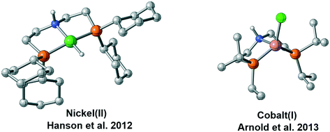 |
| | Fig. 2 Different coordination geometries of Ni(II) pincer complex and Co(I) pincer complex. | |
2. Computational details
All calculations were performed using the Gaussian 09 D.01 program.18 In order to select the most appropriate functional for our calculation, we compared a series of functionals, which are widely used in the computational studies relevant to catalytic hydrogenation reactions; eventually, we chose M06-L19 functional for this study (please see the ESI,† page S2). The ultrafine pruned (99590) calculation grid was used in all calculations. Geometry optimizations were carried out at the M06-L/BSI level (BSI designates the basis set combination of SDD20 for metal atoms and 6-31G(d, p) for nonmetal atoms). Frequency analysis calculations were performed to characterize the structures to be the minima (no imaginary frequency) or transition states (one imaginary frequency). Transition states were verified by intrinsic reaction coordinate (IRC) calculations. With M06-L/BSI geometries, the energy results were further refined by calculating single-point energy at the M06-L/BSII level with larger basis set (BSII designates SDD for metal atom and 6-311++G(d, p) for nonmetal atoms). The solvation effect of THF was simulated by the SMD continuum solvent model.21 Since the calculation is based on the ideal gas-phase model, the ignorance of the suppression effect of solvent on the translational and rotational freedoms of reactants will cause the overestimation of the entropic contribution. Therefore, we adopt the MHP scheme proposed by Martin, Hay, and Pratt, which is an approximate method to calculate entropy more accurately.22 This approach has been successfully applied to various catalytic systems and is found to produce reasonable results.23 Based on this method, a correction of 4.3 kcal mol−1 is applied when a component of the reaction changes (i.e., a reaction from m components to n components, the correction is (n–m) × 4.3 kcal mol−1). The correction for the change in standard state from 1 atm to 1 M concentration of RT![[thin space (1/6-em)]](https://www.rsc.org/images/entities/char_2009.gif) ln(24.5), i.e., 1.9 kcal mol−1 was added for all the species in solution.24 The 3D optimized structure figures in this paper were displayed using the CYLview visualization program.25 The canonical molecular orbital is depicted using the IboView program.26 Additional computational information and the Cartesian coordinates of the optimized structure are given in the ESI.†
ln(24.5), i.e., 1.9 kcal mol−1 was added for all the species in solution.24 The 3D optimized structure figures in this paper were displayed using the CYLview visualization program.25 The canonical molecular orbital is depicted using the IboView program.26 Additional computational information and the Cartesian coordinates of the optimized structure are given in the ESI.†
3. Results
Relative energies of possible isomers
To provide a detailed comparison of two complexes, all possible isomers (Fig. 3) are taken into account. Generally speaking, most d8 metal complexes tend to maintain square planar (labeled as SP-1S) geometry, in which the metal center chooses to stay at the singlet spin state. In some cases, the extra ligand, such as tetrahydrofuran (THF) or other substrate, can coordinate to the metal center to form square-based pyramidal (labeled SBP-1S) geometry. The metal complex adopts a singlet spin state. It is not possible to add extra ligands to form a six-coordinated complex, which is ascribed to the electron repulsion from the doubly occupied dz2 orbital. Meanwhile, as the PNP pincer complex is not rigid, distorted geometry (labeled as Bent-1S) is also discussed. As for the triplet spin state, two possible isomers are located. We used the square planar geometry as the starting geometry and set the spin state as triplet for optimization; a sawhorse-type complex (SH-1T) was located. Another possible triplet isomer is located with trigonal pyramidal geometry (labeled as TP-1T).
 |
| | Fig. 3 Five possible isomers and the corresponding qualitative 3d molecular orbitals. | |
We first investigate the relative stability of the isomers, and the relative free energy results are measured with respect to square planar geometry. For Co(I) pincer complex, Bent-Co-1S is highly disfavored and it is nearly 28.4 kcal mol−1 higher in free energy, which arises from the steric repulsion and distorted ligand field. For SBP geometry, with a pair of electrons occupying the dz2 orbital, adding extra ligands in the axial direction destabilizes the complex. Therefore, we can see that the SBP geometry is very unstable (SPB-Co-1S: 22.2 kcal mol−1). Interestingly, the sawhorse geometry (SH-Co-1T: −7.8 kcal mol−1) and trigonal pyramidal geometry (TP-Co-1T: −6.4 kcal mol−1) with a triplet spin state are more stable than the square planar geometry, which is consistent with the experimental observation. For Ni(II) system, the square planar geometry is the most stable coordination status. Consistent with the observations for Co(I), we can see that the SBP geometry is very unstable (SPB-Ni-1S 17.3 kcal mol−1) as well. The bent geometry (Bent-Ni-1S) is highly disfavored and it is nearly 34.8 kcal mol−1 higher in free energy. In contrast to the observations for Co(I), the triplet spin states in the sawhorse geometry and trigonal pyramidal geometry are found to be less plausible, with the free energies of 17.9 kcal (SH-Ni-1T) and 24.2 kcal mol−1 (TP-Ni-1T), respectively, which are consistent with the experimentally observed low spin state of Ni(II) pincer complex. Even though the relative stability of the isomers is known, it is still necessary to further explore the reactivity of each species because the unstable species may exhibit better activity during the actual catalytic processes. Starting from the five isomers shown in Fig. 3, different reaction pathways are investigated to further confirm whether the difference in spin state and geometry can affect the mechanistic preference. We intend to provide a comprehensive view of all the possible mechanisms.
Non-bifunctional mechanism pathway via square planar geometry (singlet)
The corresponding free energy profiles are shown in Scheme 1. The inner-sphere mechanism normally consists of two steps. The first step is M–H insertion into the C![[double bond, length as m-dash]](https://www.rsc.org/images/entities/char_e001.gif) O bond. The second step is the regeneration of the catalyst. For the Co(I) catalyst, although the square planar geometry in singlet spin state is slightly higher than the sawhorse geometry at triplet state, the M–H insertion process seems to be facile (SP-Co-1S → SP-Co-TS1S, ΔG≠ = 9.4 kcal mol−1). The regeneration of metal hydride viaSP-Co-TS2S (ΔG≠ = 28.7 kcal mol−1) is the rate-determining step of the square planar pathway, which is found to proceed via a σ-bond metathesis-type mechanism. The hydrogen bonds from the iPr moiety are 2.47 Å and 2.41 Å (please see page S8 in ESI†) for SP-Co-TS2S and SP-Ni-TS2S, respectively, which can stabilize the transition state to facilitate the sigma bond metathesis-type process to regenerate the metal hydride. On the contrary, M–H insertion mediated by Ni(II) catalysts is found to be much higher in activation free energy (ΔG≠ = 27.4 kcal mol−1). The heterolytic cleavage of H2viaSP-Ni-TS2S (ΔG≠ = 40.6 kcal mol−1) is even higher with respect to activation free energy. To summarize, the overall energy barrier of the non-bifunctional square planar pathway is 28.7 kcal mol−1 for Co(I) complex (SP-Co-1S → SP-Co-TS2S) and 40.6 kcal mol−1 for Ni(II) complex (SP-Ni-1S → SP-Ni-TS2S).
O bond. The second step is the regeneration of the catalyst. For the Co(I) catalyst, although the square planar geometry in singlet spin state is slightly higher than the sawhorse geometry at triplet state, the M–H insertion process seems to be facile (SP-Co-1S → SP-Co-TS1S, ΔG≠ = 9.4 kcal mol−1). The regeneration of metal hydride viaSP-Co-TS2S (ΔG≠ = 28.7 kcal mol−1) is the rate-determining step of the square planar pathway, which is found to proceed via a σ-bond metathesis-type mechanism. The hydrogen bonds from the iPr moiety are 2.47 Å and 2.41 Å (please see page S8 in ESI†) for SP-Co-TS2S and SP-Ni-TS2S, respectively, which can stabilize the transition state to facilitate the sigma bond metathesis-type process to regenerate the metal hydride. On the contrary, M–H insertion mediated by Ni(II) catalysts is found to be much higher in activation free energy (ΔG≠ = 27.4 kcal mol−1). The heterolytic cleavage of H2viaSP-Ni-TS2S (ΔG≠ = 40.6 kcal mol−1) is even higher with respect to activation free energy. To summarize, the overall energy barrier of the non-bifunctional square planar pathway is 28.7 kcal mol−1 for Co(I) complex (SP-Co-1S → SP-Co-TS2S) and 40.6 kcal mol−1 for Ni(II) complex (SP-Ni-1S → SP-Ni-TS2S).
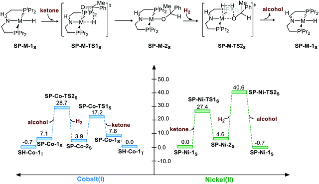 |
| | Scheme 1 The square planar pathway of hydrogenation of ketones. The relative free energies are given in kcal mol−1. | |
Bifunctional MLC mechanism pathway via sawhorse geometry (triplet)
The hydrogenation via the bifunctional MLC mechanism starts with sawhorse geometry. The spin state of both the complexes is triplet. The bifunctional MLC mechanism involves two stages. The first stage is the bifunctional double hydrogen transfer (BDHT) mechanism,27 which is found to proceed in a stepwise manner. The hydride first attacks the carbon atom of the carbonyl group, which generates a transient ion-pair adduct intermediate. The N–H group of the pincer ligand then transfers the proton to the alkyl oxide intermediate. During the second stage, the amide and the metal center then cleave the H2 bond and regenerate the catalyst. For Co(I) complex, the free energy barrier for the first BDHT process viaSH-Co-TS1T-a is rather low (ΔG≠ = 4.2 kcal mol−1). The hydrogen bonds between the N–H site and the oxygen atom of ketone are 1.84 Å and 1.65 Å (please see page S8 in ESI†) for SH-Co-TS1T-a and SH-Ni-TS1T-a, respectively, which can facilitate the hydrogenation of substrate and regenerate the metal hydride complex with the induction effect. The second proton transfer viaSH-Co-TS1T-b (ΔG≠ = −3.6 kcal mol−1) is even lower than that for the intermediate SH-Co-2T (ΔG = −2.8 kcal mol−1) in free energy. This is understandable as the transition state is located at the electronic potential energy surface. The electronic energy of SH-Co-TS1T-b is 1.3 kcal mol−1 higher than that of SH-Co-2T. The heterolytic cleavage of H2viaSH-Co-TS2T (ΔG≠ = 17.6 kcal mol−1) is still the rate-determining step. The overall free energy barrier of the bifunctional MLC mechanism for Co(I)–PNP complex is 20.4 kcal mol−1 (SH-Co-2T → SH-Co-TS2T). For Ni(II) complex, BDHT occurs via a stepwise process. The hydride transfer occurs viaSH-Ni-TS1T-a (ΔG≠ = 27.4 kcal mol−1). After a transient intermediate SH-Ni-2T, the BDHT process ends via the proton transfer (SH-Ni-TS1T-b: ΔG≠ = 28.8 kcal mol−1). The hydrogen cleavage viaSH-Ni-TS2T is 43.3 kcal mol−1 in free energy. The calculation results also imply that the higher energy barrier of bifunctional MLC mechanism for Ni(II)–PNP complex is caused by the triplet/singlet energy gap as the activation free energy barrier is only 25.4 kcal mol−1 (SH-Ni-1T → SH-Ni-TS2T). The overall energy barrier of the bifunctional MLC mechanism for Ni(II)–PNP complex is 43.3 kcal mol−1 (SP-Ni-1S → SH-Ni-TS2T) (Scheme 2).
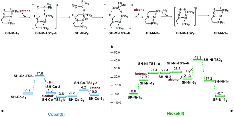 |
| | Scheme 2 The sawhorse pathway of hydrogenation of ketones. The relative free energies are given in kcal mol−1. | |
Non-bifunctional mechanism pathway via bent geometry (singlet)
Because the pincer ligand is not rigid, hydrogenation can also be promoted via a bent geometry pathway. However, the bent geometry is highly unstable in free energy in both Co(I) and Ni(II) complexes. The bent pincer complex can be considered to have square pyramidal geometry with a vacant site. Thus, adding ketone as an extra ligand significantly stabilizes the complex for both complexes (Bent-Co-1S → Bent-Co-2S: ΔG = −20.9 kcal mol−1 and Bent-Ni-1S → Bent-Ni-2S: ΔG = −11.6 kcal mol−1). Then, the M–H insertion process occurs with the bent pincer geometry. The calculation indicates that M–H insertion is much lower in the bent geometry pathway than that in the square planar pathway for both the cases (Bent-Co-2S → Bent-Co-TS1S: ΔG≠ = 5.7 kcal mol−1 and Bent-Ni-2S → Bent-Ni-TS1S: ΔG≠ = 1.2 kcal mol−1); this results from the bent geometry that relieves the steric effect between the substrate and the pendent iPr groups. However, regeneration of the metal hydride via the σ-bond metathesis-type process still has to overcome high free energy barrier for both the Co(I) and Ni(II) complexes. Therefore, the overall activation free energy in bent geometry pathway is above 40 kcal mol−1 for both the complexes (Bent-Co-1S → Bent-Co-TS2S, ΔG≠ = 40.3 kcal mol−1; Bent-Ni-1S → Bent-Ni-TS2S, ΔG≠ = 44.8 kcal mol−1) (Scheme 3).
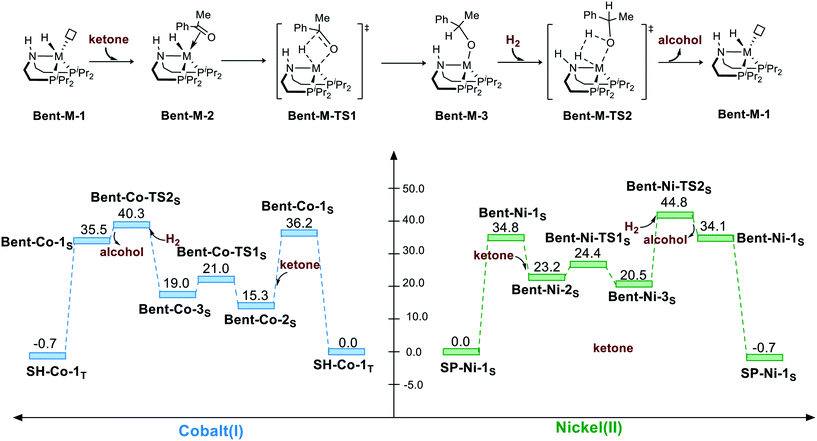 |
| | Scheme 3 The bent geometry pathway of the hydrogenation of ketone. The relative free energies are given in kcal mol−1. | |
Bifunctional MLC mechanism via square-based pyramidal geometry (singlet)
Another possibility of bifunctional MLC mechanism is BDHT through the square-based pyramidal geometry. By adding an extra ligand, the hydride isomerizes to the cis-site of the N–H proton. However, adding an extra ligand to the axis leads to electronic repulsion between the filled dz2 orbital and the extra ligand. Therefore, the coordination of the extra ligand is not favored in both cases. The BDHT process occurs in a concerted manner, which is different from the sawhorse geometry situation. During the transition state, the extra ligand will isomerize from the trans site of hydride to the trans site of the nitrogen atom of the N–H group because the complex has a d8 metal center, which tends to maintain a square planar geometry at singlet state. After the heterolytic cleavage of H2, the catalyst is regenerated. For the Co(I) catalyst, the BDHT process viaSBP-Co-TS1S exhibits 29.0 kcal mol−1 free energy, and it is even lower in free energy as compared to that for the reactant SBP-Co-1S. BDHT of Ni(II) via SBP geometry viaSBP-Ni-TS1S also has a very low activation free energy (ΔG≠ = 22.6 kcal mol−1). However, the transition state of H2 cleavage is rather high in free energy for both the cases (SBP-Co-TS2S, ΔG≠ = 41.5 kcal mol−1; SBP-Ni-TS2S, ΔG≠ = 49.7 kcal mol−1) because the regenerated five-coordinated complex is not stable as a d8 metal complex. For the SBP pathway, the overall activation free energy is 41.5 kcal mol−1 (TH-Co-1T → SBP-Co-TS2S) for the Co(I) complex and 49.7 kcal mol−1 (SP-Ni-1S → SBP-Ni-TS2S) for the Ni(II) pincer complex (Scheme 4).
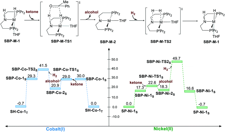 |
| | Scheme 4 The square-based pyramidal pathway of hydrogenation of ketone. The relative free energies are given in kcal mol−1. | |
Bifunctional MLC mechanism via trigonal pyramidal geometry (triplet, bent ligand)
Bifunctional MLC mechanism can proceed via trigonal pyramidal geometry. The hydrogenation process operates in a stepwise manner. The hydride is first transferred to the carbon atom of the carbonyl group, which yields a metal alkyl oxide as an intermediate. Then, the proton will transfer to the alkyl oxide, which generates alcohol as the product. After the release of alcohol, the bent pincer complex is restored to square planar geometry, and it undergoes heterolytic cleavage of H2. For both the pincer complexes, the hydride transfer is found to have a very low activation free energy relative to that for TP-M-1T (M represents Co or Ni) as the starting point (TP-Co-1T → TP-Co-TS1T-a, ΔG≠ = 2.5 kcal mol−1; TP-Ni-1T → TP-Ni-TS1T-a, ΔG≠ = 7.5 kcal mol−1). Then, the metal alkyl oxide is found to coordinate to the metal center, which is fairly stable thermodynamically (TP-Co-2T, ΔG≠ = −17.6 kcal mol−1; TP-Co-2T, ΔG≠ = 9.4 kcal mol−1). Therefore, the subsequent proton transfer and H2 cleavage have to overcome a high energy barrier. Thus, the overall activation free energy is 35.2 kcal mol−1 (TP-Co-2T → TP-Co-TS2T) for the Co(I) complex and 43.3 kcal mol−1 (SP-Ni-1S → TP-Ni-TS2T) for the Ni(II) pincer complex (Scheme 5).
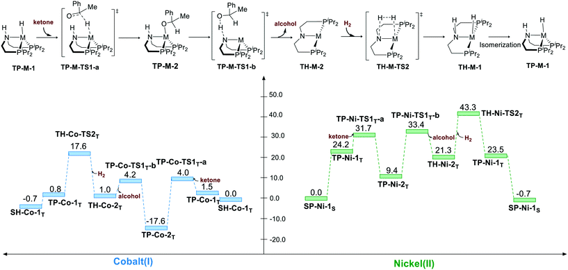 |
| | Scheme 5 The trigonal pyramidal pathway of the hydrogenation of ketone. The relative free energies are given in kcal mol−1. | |
The overall free energy barrier results of each reaction pathway are summarized in Table 1. Current results indicate that the Ni(II) hydride complex chooses to promote the catalytic hydrogenation reaction via an inner-sphere mechanism, which is in excellent agreement with experimental observation. On the contrary, the Co(I) hydride complex prefers to proceed via the bifunctional MLC mechanism in sawhorse geometry. The mechanism via ligand rotation is found to be less plausible as the PNP ligand is not a typical hemilabile ligand (ESI,† page S6). Further discussion will be focused on the preference of spin state and mechanism.
Table 1 The overall free energy barriers in different reaction pathwaysa
| Metal |
SP (singlet) |
SH (triplet) |
Bent (singlet) |
SBP (singlet) |
TP (triplet) |
|
The relative free energies are given in kcal mol−1.
|
| Co(I) |
28.7 |
20.4 |
40.3 |
41.5 |
35.2 |
| Ni(II) |
40.6 |
43.3 |
44.8 |
49.7 |
43.3 |
4. Discussion
The origin of the preference for different spin states and geometries
With detailed exploration of the possible reaction pathways, the mechanistic preference of two d8 complexes is mainly ascribed to the preference of the different spin states and coordination geometries. Therefore, it is necessary to understand the reason for the calculated results. The isomerization from the singlet state square planar geometry to the triplet state sawhorse geometry can be considered with approximately two stages, i.e., the change in the electronic structure in the metal center and the isomerization of the pincer ligand. Therefore, we calculate the free energy change in these two processes. The results are shown in Fig. 4. As we can see, the free energy changes of both the complexes increase when excitation occurs from the singlet state to the triplet state. However, the free energy of the triplet Co complex at square planar geometry only increases by 17.5 kcal mol−1. On the contrary, the relative free energy of nickel complex increases by 45.5 kcal mol−1. The following isomerization process from square planar to sawhorse stabilizes the complex as two electrons singly occupy the degenerate orbitals. Therefore, the free energy changes of two complexes are close to each other (−27.6 kcal mol−1 and −25.3 kcal mol−1). Thus, the calculated data indicate that the excitation energies are significantly different between the Co(I) and the Ni(II) metal centers (Fig. 5).
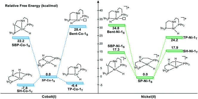 |
| | Fig. 4 The free energy profile of the relative active species. Free energy results are reported in kcal mol−1. | |
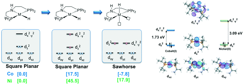 |
| | Fig. 5 Qualitative MO analysis of the change in ligand field. Free energy results are reported in kcal mol−1. | |
We further check the HOMO–LUMO gap of Co(I) and the Ni(II) complexes at the square planar geometry. The HOMO–LUMO gaps of the Co(I) and the Ni(II) complexes are 1.73 eV and 3.09 eV, respectively, which are consistent with the trend of the free energy change from singlet to triplet of these two d8 metal centers. As both d8 NiII and CoI complexes have the same ligand, the only difference is the oxidation state of the metal. With increased Zeff value of NiII, the ligand binds in a stronger manner to a NiII center than to a CoI center. The smaller distance between the ligand and the Ni(II) center results in stronger repulsion between the ligand and metal electrons, which finally leads to a larger splitting gap. The intrinsic difference in oxidation state and effective nuclear charge between Ni(II) and Co(I) should be the origin of the observed high spin preference, which further leads to different outer sphere bifunctional mechanistic preferences during the catalysis process. The calculation results indicate that the Co(I)–PNP complex will proceed in a metal–ligand cooperation manner during the hydrogenation reaction of acetophenone. To the best of our knowledge, this kind of Co(I) bifunctional catalyst has not been reported yet.28 Therefore, the unique preference in spin state, coordination geometry and catalytic mechanism of Co(I) pincer complex exhibits its potential to become an effective MLC catalyst. These results should be informative for future catalyst design.
The difference in the energy gaps caused by ligand field splitting also implies another important information: with a larger gap between the bonding orbital and the antibonding orbital, the Ni(II) complex is more stable than the Co(I) pincer complex thermodynamically. The relative stability is also reflected in the structure of the pincer complex. The M–H bond of Ni(II) is shorter than that of Co(I) in both singlet and triplet spin states (Fig. 6). Further natural population analysis indicates that the NPA charges of metal hydride are −0.026 and −0.091 for SP-Ni-1S and SH-Ni-1T, respectively; the values are −0.095 and −0.156 for SP-Co-1S and SH-Co-1T, respectively. This indicates that Ni(II) hydride is more inert compared with Co(I) hydride, which accounts for the high activation barrier of Ni(II) pincer complex in each pathway. Since stability and activity are both crucial for catalyst design, it is necessary to find a balance between these two important factors.
 |
| | Fig. 6 The difference in M–H bond lengths between Co(I) and Ni(II) complexes. Bond lengths are in angstroms. | |
DFT evaluation of three Ni(II) MLC catalyst models
For Ni(II) metal center, the metal hydride is rather inert as the activation free energy barriers are all very high in each pathway. Therefore, it is necessary to activate the hydride by tailored ligand design. Moreover, the complex has a strong tendency to maintain square planar geometry. Using extra ligand or isomerization will neither change the original ligand field nor decrease the stability of the complex. Therefore, bifunctional active sites can be introduced on the cis-site of the metal hydride, which can achieve metal–ligand cooperation catalysis without causing energy penalty from changing the ligand field. Recently, Wendt et al. synthesized a series of Pd(II) and Ni(II) complexes using an unsymmetrical PCN (1-(3-((ditert-butylphosphino)methyl)-phenyl)-N,N-dimethyl-methanamine) pincer ligand;29 they are effective catalysts for CO2 activation and C–C bond formation reaction. Milstein et al. prepared a Co pincer complex, in which the active site is installed at the cis-site of the metal hydride.17 Inspired by these interesting catalyst design strategies, three Ni(II) bifunctional catalyst models are computationally designed as Mod. A, B and C, which may have the potential to exhibit metal–ligand cooperation. For Mod. A, we simply modify the Ni(II)–PNP complex by replacing one of the PiPr2 moieties with NHiPr moiety. Using the same ligand of Mod. A, the N–H moiety in Mod. Btrans to the hydride is deprotonated to compare the trans-effect between neutral ligand and anionic ligand. Based on the Ni(II)–PCN complex synthesized by Wendt et al., Mod. C is designed for further exploring the potential activity of Ni(II) bifunctional catalysts. To maintain the same steric and electronic effect as that of the Ni(II)–PNP pincer catalyst, the iPr ligand is utilized throughout the calculations (Fig. 7)
 |
| | Fig. 7 Three proposed Ni(II) model catalysts. Bond lengths are in angstroms. | |
The DFT calculated free energy results along the reaction coordinate are shown in Fig. 8. The transition state (TS1) of the BDHT mechanism can be located. However, the activation free energy of A-TS1 for Mod. A is rather high (ΔG≠ = 32.6 kcal mol−1) as the nickel hydride is quite inert. Simply replacing the N–H group with the N anion significantly lowers the free energy barrier (B-TS1: ΔG≠ = 17.2 kcal mol−1). The utilization of the pincer ligand with the benzene ring in Mod. C is even better with only 15.5 kcal mol−1 activation free energy (C-TS1). However, the relative electronic energy of the intermediate IM1 after hydride transfer is very close to that of the transition state, which leads to a higher free energy compared with that of the transition state TS1. For further hydride regeneration process, Mod. C has the lowest free energy barrier compared with Mod. A and Mod. B. The hydride regeneration step viaC-TS2 needs to overcome a free energy barrier of 31.4 kcal mol−1 at least. Compared with the calculated free energy barrier (SP-Ni-TS2S: ΔG≠ = 40.6 kcal mol−1) of the Ni(II)–PNP catalyst without functional group on the cis-site of hydride, it is nearly 10 kcal mol−1 lower in free energy. Therefore, installing the functional group on the cis-site can enable the metal ligand cooperation process for Ni(II) pincer catalyst without causing extra energy penalty. In addition, the trans-effect can lead to better hydride transfer activity. These results can be helpful for the rational design of metal ligand cooperative catalysts in the future.
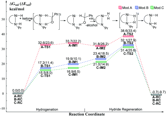 |
| | Fig. 8 The relative free energy profile of the model catalysts. Free energy results are reported in kcal mol−1. | |
5. Conclusion
DFT studies were performed to shed light on different preferences in spin state, coordination geometry and catalytic mechanism between two representative d8 metal complexes. The Co(I)–PNP complex prefers the bifunctional MLC pathway via sawhorse geometry in triplet state. On the contrary, the Ni(II) complex favors an inner-sphere non-bifunctional MLC mechanism via square planar geometry in singlet state, which is in agreement with former experimental observations. The intrinsic difference in oxidation state and effective nuclear charge between Ni(II) and Co(I) should be the origin of such dichotomy, which is reflected in the HOMO–LUMO gaps. The calculated results further imply the interplay between the stability and activity for pincer complexes. Three computationally designed Ni(II) catalysts bearing a functional group at cis position are proposed and investigated, which exhibit the potential to become efficient Ni(II) MLC catalysts. This study highlights the intrinsic characteristics of first-row transition metals in mechanism variation, which should provide helpful information for future catalyst design.
Conflicts of interest
There are no conflicts to declare.
Acknowledgements
This work was supported by the NSFC (21473261, 21573292, 21673301, 21773312, and 21803014), the Guangdong Natural Science Funds for Distinguished Young Scholars (No. 2015A030306027), the Tip-top Youth Talents of Guangdong special support program (No. 20153100042090537), the Natural Science Foundation of Guangxi (No. 2018GXNSFBA138041) and the Fundamental Research Funds for the Central Universities.
References
- L. Yinwu, Z. Jianyu, S. Siwei, S. Youxiang, L. Yan and K. Zhuofeng, Chin. J. Org. Chem., 2017, 37, 2187–2202 CrossRef;
D. J. Cole-Hamilton and R. P. Tooze, Catalyst Separation, Recovery and Recycling., 2006, vol. 2006, p. 8 Search PubMed.
- F. Kallmeier and R. Kempe, Angew. Chem., Int. Ed., 2017, 57, 46–60 CrossRef PubMed.
- T. Zell and D. Milstein, Acc. Chem. Res., 2015, 48, 1979–1994 CrossRef CAS PubMed.
-
(a) Z. Zhang, Y. Li, C. Hou, C. Zhao and Z. Ke, Catal. Sci. Technol., 2018, 8, 656–666 RSC;
(b) P. J. Chirik, Acc. Chem. Res., 2015, 48, 1687–1695 CrossRef CAS PubMed.
- N. A. Eberhardt and H. Guan, Chem. Rev., 2016, 116, 8373–8426 CrossRef CAS PubMed.
- T. Zell, Y. Ben-David and D. Milstein, Angew. Chem., 2014, 126, 4773–4777 CrossRef.
- S. Chakraborty, H. Dai, P. Bhattacharya, N. T. Fairweather, M. S. Gibson, J. A. Krause and H. Guan, J. Am. Chem. Soc., 2014, 136, 7869–7872 CrossRef CAS PubMed.
- S. Werkmeister, K. Junge, B. Wendt, E. Alberico, H. Jiao, W. Baumann, H. Junge, F. Gallou and M. Beller, Angew. Chem., Int. Ed., 2014, 53, 8722–8726 CrossRef CAS PubMed.
- C. Bornschein, S. Werkmeister, B. Wendt, H. Jiao, E. Alberico, W. Baumann, H. Junge, K. Junge and M. Beller, Nat. Commun., 2014, 5, 4111–4121 CrossRef CAS PubMed.
- S. Chakraborty, P. Bhattacharya, H. Dai and H. Guan, Acc. Chem. Res., 2015, 48, 1995–2003 CrossRef CAS PubMed.
-
(a) G. Q. Zhang, K. V. Vasudevan, B. L. Scott and S. K. Hanson, J. Am. Chem. Soc., 2013, 135, 8668–8681 CrossRef CAS PubMed;
(b) G. Zhang and S. K. Hanson, Chem. Commun., 2013, 49, 10151–10153 RSC;
(c) G. Zhang and S. K. Hanson, Org. Lett., 2013, 15, 650–653 CrossRef CAS PubMed.
- C. Hou, J. Jiang, Y. Li, Z. Zhang, C. Zhao and Z. Ke, Dalton Trans., 2015, 44, 16573–16585 RSC.
- C. Hou, J. Jiang, S. Zhang, G. Wang, Z. Zhang, Z. Ke and C. Zhao, ACS Catal., 2014, 4, 2990–2997 CrossRef CAS.
-
(a) P. J. Chirik and K. Wieghardt, Science, 2010, 327, 794–795 CrossRef CAS PubMed;
(b) S. C. Bart, E. Lobkovsky and P. J. Chirik, J. Am. Chem. Soc., 2004, 126, 13794–13807 CrossRef CAS PubMed.
- K. V. Vasudevan, B. L. Scott and S. K. Hanson, Eur. J. Inorg. Chem., 2012, 2012, 4898–4906 CrossRef CAS.
-
(a) S. S. Rozenel, R. Padilla and J. Arnold, Inorg. Chem., 2013, 52, 11544–11550 CrossRef CAS PubMed;
(b) A. Z. Spentzos, C. L. Barnes and W. H. Bernskoetter, Inorg. Chem., 2016, 55, 8225–8233 CrossRef CAS PubMed.
-
(a) D. Srimani, A. Mukherjee, A. F. Goldberg, G. Leitus, Y. Diskin-Posner, L. J. Shimon, Y. Ben David and D. Milstein, Angew. Chem., Int. Ed., 2015, 54, 12357–12360 CrossRef CAS PubMed;
(b) A. Mukherjee, D. Srimani, S. Chakraborty, Y. Ben-David and D. Milstein, J. Am. Chem. Soc., 2015, 137, 8888–8891 CrossRef CAS PubMed.
-
M. J. T. Frisch, G. W. Trucks, H. B. Schlegel, G. E. Scuseria, M. A. Robb, J. R. Cheeseman, G. Scalmani, V. Barone, B. Mennucci, G. A. Petersson, H. Nakatsuji, M. Caricato, X. Li, H. P. Hratchian, A. F. Izmaylov, J. Bloino, G. Zheng, J. L. Sonnenberg, M. Hada, M. Ehara, K. Toyota, R. Fukuda, J. Hasegawa, M. Ishida, T. Nakajima, Y. Honda, O. Kitao, H. Nakai, T. Vreven, J. A. Montgomery Jr., J. E. Peralta, F. Ogliaro, M. Bearpark, J. J. Heyd, E. Brothers, K. N. Kudin, V. N. Staroverov, T. Keith, R. Kobayashi, J. Normand, K. Raghavachari, A. Rendell, J. C. Burant, S. S. Iyengar, J. Tomasi, M. Cossi, N. Rega, J. M. Millam, M. Klene, J. E. Knox, J. B. Cross, V. Bakken, C. Adamo, J. Jaramillo, R. Gomperts, R. E. Stratmann, O. Yazyev, A. J. Austin, R. Cammi, C. Pomelli, J. W. Ochterski, R. L. Martin, K. Morokuma, V. G. Zakrzewski, G. A. Voth, P. Salvador, J. J. D. Dannenberg, S. Dapprich, A. D. Daniels, O. Farkas, J. B. Foresman, J. V. Ortiz, J. Cioslowski and D. J. Fox, Gaussian 09, Revision D.01., Gaussian, Inc., Wallingford CT, 2013 Search PubMed.
-
(a) Y. Zhao and D. G. Truhlar, Acc. Chem. Res., 2008, 41, 157–167 CrossRef CAS PubMed;
(b) Y. Zhao and D. G. Truhlar, Theor. Chem. Acc., 2008, 120, 215–241 Search PubMed;
(c) C. Wang, J. Wang, Q. Cai, Z. Li, H.-K. Zhao and R. Luo, Comput. Theor. Chem., 2013, 1024, 34–44 Search PubMed.
- M. Dolg, U. Wedig, H. Stoll and H. Preuss, J. Chem. Phys., 1987, 86, 866–872 CrossRef CAS.
- A. V. Marenich, C. J. Cramer and D. G. Truhlar, J. Phys. Chem. B, 2009, 113, 6378–6396 CrossRef CAS PubMed.
- R. L. Martin, P. J. Hay and L. R. Pratt, J. Phys. Chem. A, 1998, 102, 3565–3573 CrossRef CAS.
-
(a) C. Song, S. Qu, Y. Tao, Y. Dang and Z.-X. Wang, ACS Catal., 2014, 4, 2854–2865 CrossRef CAS;
(b) S. Qu, Y. Dang, M. Wen and Z.-X. Wang, Chem. – Eur. J., 2013, 19, 3827–3832 CrossRef CAS PubMed;
(c) S. Qu, Y. Dang, C. Song, M. Wen, K.-W. Huang and Z.-X. Wang, J. Am. Chem. Soc., 2014, 136, 4974–4991 CrossRef CAS PubMed;
(d) S. Qu, Y. Dang, C. Song, J. Guo and Z.-X. Wang, ACS Catal., 2015, 6386–6396 CrossRef CAS;
(e) S. Qu, H. Dai, Y. Dang, C. Song, Z.-X. Wang and H. Guan, ACS Catal., 2014, 4, 4377–4388 CrossRef CAS;
(f) H. Li, M. Wen and Z.-X. Wang, Inorg. Chem., 2012, 51, 5716–5727 CrossRef CAS PubMed;
(g) H. Li, M. Wen, G. Lu and Z.-X. Wang, Dalton Trans., 2012, 41, 9091–9100 RSC;
(h) H. Li, X. Wang, M. Wen and Z.-X. Wang, Eur. J. Inorg. Chem., 2012, 2012, 5011–5020 CrossRef CAS;
(i) H. Li, X. Wang, F. Huang, G. Lu, J. Jiang and Z.-X. Wang, Organometallics, 2011, 30, 5233–5247 CrossRef CAS;
(j) H. Li, G. Lu, J. Jiang, F. Huang and Z.-X. Wang, Organometallics, 2011, 30, 2349–2363 CrossRef CAS;
(k) Y. F. Dang, S. L. Qu, Z. X. Wang and X. T. Wane, J. Am. Chem. Soc., 2014, 136, 986–998 CrossRef CAS PubMed;
(l) Y. Dang, S. Qu, Y. Tao, X. Deng and Z.-X. Wang, J. Am. Chem. Soc., 2015, 137, 6279–6291 CrossRef CAS PubMed;
(m) Y. Dang, S. Qu, J. W. Nelson, H. D. Pham, Z.-X. Wang and X. Wang, J. Am. Chem. Soc., 2015, 137, 2006–2014 CrossRef CAS PubMed;
(n) T. Chen, H. Li, S. Qu, B. Zheng, L. He, Z. Lai, Z.-X. Wang and K.-W. Huang, Organometallics, 2014, 33, 4152–4155 CrossRef CAS.
- L. Vigara, M. Z. Ertem, N. Planas, F. Bozoglian, N. Leidel, H. Dau, M. Haumann, L. Gagliardi, C. J. Cramer and A. Llobet, Chem. Sci., 2012, 3, 2576–2586 RSC.
-
C. Y. Legault, CYLview, 1.0b, Université de Sherbrooke, 2009, Online at http://www.cylview.org Search PubMed.
- G. Knizia and J. E. M. N. Klein, Angew. Chem., Int. Ed., 2015, 54, 5518–5522 CrossRef CAS PubMed.
-
(a) C. Hou, J. Jiang, Y. Li, C. Zhao and Z. Ke, ACS Catal., 2017, 7, 786–795 CrossRef CAS;
(b) C. Hou, Z. Zhang, C. Zhao and Z. Ke, Inorg. Chem., 2016, 55, 6539–6551 CrossRef CAS PubMed.
- V. Papa, K. Junge and M. Beller, Chem. – Eur. J., 2018 DOI:10.1002/chem.201803016.
-
(a) A. H. Mousa, J. Bendix and O. F. Wendt, Organometallics, 2018, 37, 2581–2593 CrossRef CAS;
(b) A. H. Mousa, A. Fleckhaus, M. Kondrashov and O. F. Wendt, J. Organomet. Chem., 2017, 845, 157–164 CrossRef CAS;
(c) A. Fleckhaus, A. H. Mousa, N. S. Lawal, N. K. Kazemifar and O. F. Wendt, Organometallics, 2015, 34, 1627–1634 CrossRef CAS.
Footnote |
| † Electronic supplementary information (ESI) available. See DOI: 10.1039/c8cy01862f |
|
| This journal is © The Royal Society of Chemistry 2019 |
Click here to see how this site uses Cookies. View our privacy policy here.  *a
*a
![[thin space (1/6-em)]](https://www.rsc.org/images/entities/char_2009.gif) ln(24.5), i.e., 1.9 kcal mol−1 was added for all the species in solution.24 The 3D optimized structure figures in this paper were displayed using the CYLview visualization program.25 The canonical molecular orbital is depicted using the IboView program.26 Additional computational information and the Cartesian coordinates of the optimized structure are given in the ESI.†
ln(24.5), i.e., 1.9 kcal mol−1 was added for all the species in solution.24 The 3D optimized structure figures in this paper were displayed using the CYLview visualization program.25 The canonical molecular orbital is depicted using the IboView program.26 Additional computational information and the Cartesian coordinates of the optimized structure are given in the ESI.†
![[double bond, length as m-dash]](https://www.rsc.org/images/entities/char_e001.gif) O bond. The second step is the regeneration of the catalyst. For the Co(I) catalyst, although the square planar geometry in singlet spin state is slightly higher than the sawhorse geometry at triplet state, the M–H insertion process seems to be facile (SP-Co-1S → SP-Co-TS1S, ΔG≠ = 9.4 kcal mol−1). The regeneration of metal hydride viaSP-Co-TS2S (ΔG≠ = 28.7 kcal mol−1) is the rate-determining step of the square planar pathway, which is found to proceed via a σ-bond metathesis-type mechanism. The hydrogen bonds from the iPr moiety are 2.47 Å and 2.41 Å (please see page S8 in ESI†) for SP-Co-TS2S and SP-Ni-TS2S, respectively, which can stabilize the transition state to facilitate the sigma bond metathesis-type process to regenerate the metal hydride. On the contrary, M–H insertion mediated by Ni(II) catalysts is found to be much higher in activation free energy (ΔG≠ = 27.4 kcal mol−1). The heterolytic cleavage of H2viaSP-Ni-TS2S (ΔG≠ = 40.6 kcal mol−1) is even higher with respect to activation free energy. To summarize, the overall energy barrier of the non-bifunctional square planar pathway is 28.7 kcal mol−1 for Co(I) complex (SP-Co-1S → SP-Co-TS2S) and 40.6 kcal mol−1 for Ni(II) complex (SP-Ni-1S → SP-Ni-TS2S).
O bond. The second step is the regeneration of the catalyst. For the Co(I) catalyst, although the square planar geometry in singlet spin state is slightly higher than the sawhorse geometry at triplet state, the M–H insertion process seems to be facile (SP-Co-1S → SP-Co-TS1S, ΔG≠ = 9.4 kcal mol−1). The regeneration of metal hydride viaSP-Co-TS2S (ΔG≠ = 28.7 kcal mol−1) is the rate-determining step of the square planar pathway, which is found to proceed via a σ-bond metathesis-type mechanism. The hydrogen bonds from the iPr moiety are 2.47 Å and 2.41 Å (please see page S8 in ESI†) for SP-Co-TS2S and SP-Ni-TS2S, respectively, which can stabilize the transition state to facilitate the sigma bond metathesis-type process to regenerate the metal hydride. On the contrary, M–H insertion mediated by Ni(II) catalysts is found to be much higher in activation free energy (ΔG≠ = 27.4 kcal mol−1). The heterolytic cleavage of H2viaSP-Ni-TS2S (ΔG≠ = 40.6 kcal mol−1) is even higher with respect to activation free energy. To summarize, the overall energy barrier of the non-bifunctional square planar pathway is 28.7 kcal mol−1 for Co(I) complex (SP-Co-1S → SP-Co-TS2S) and 40.6 kcal mol−1 for Ni(II) complex (SP-Ni-1S → SP-Ni-TS2S).


