Controlling the growth of fullerene C60 cones under continuous flow†
Ibrahim K.
Alsulami
,
Thaar M. D.
Alharbi
,
David P.
Harvey
,
Christopher T.
Gibson
 and
Colin L.
Raston
 *
*
Centre for NanoScale Science and Technology (CNST), College of Science and Engineering, Flinders University, Adelaide, SA 5042, Australia. E-mail: colin.raston@flinders.edu.au
First published on 14th June 2018
Abstract
Micromixing of an o-xylene solution of C60 with N-N-dimethylformamide (DMF) at room temperature under continuous flow in a vortex fluidic device (VFD) results in the formation of symmetrical right cones in high yield with diameters 0.5 to 2.5 μm, pitch angle 25° to 55° and wall thickness 120 to 310 nm. Their formation is in the absence of surfactants and any other reagents, and is scalable. The cones are formed at specific operating parameters of the VFD, including rotational speed, flow rate and concentration, and varying these results in other structures such as grooved fractals. Other aromatic solvents in place of o-xylene results in the formation of rods, spicules and prisms, respectively for m-xylene, p-xylene and mesitylene.
Carbon nano-materials are emerging as key components for future technology, for developing complex functional structures devoid of potentially toxic metals and metals which are likely to have supply chain issues in the near future.1 Fullerene C60 is a molecule of carbon in the form of a hollow sphere, 1 nm in diameter, having sp2 carbon atoms arranged on a curved surface, at the vertices of a truncated icosahedron.2 It has unique optical and optoelectronic properties, being an excellent electron acceptor, with high photosensitivity and high electron mobility.2,3 Fullerene C60 has a number of applications covering photodetectors, sensors solar cells, light emitting diodes and drug delivery.2–4
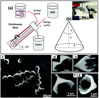
Various methods have been devised on assembling C60 into different spatial arrangements, as a strategy for developing materials with different properties and potential applications. Such methods include liquid–liquid interfacial precipitation (LLIP),4 drop-drying,5 solution driven self-assembly and slow evaporation.6 The different spatial arrangements include those found in nano-rods, nano-whiskers, nano-tubules, flowers, nano-bowls and nano-sheets.1–7 However, there are a number of limitations and drawbacks of these methods, notably the high cost of processing, the use of other reagents and/or surfactants potential covering the surface of the material, high temperature processing which has a high-energy penalty, and limited scope for scaling up the process. A challenge is to develop scalable, low-cost methods high in green chemistry or sustainability metrics, for gaining access to novel structures of C60, in a way which could also be applicable to other fullerenes and mixtures thereof. To this end we have explored the use of continuous flow processing to fabricate fullerene C60 nano-structures using the vortex fluidic device (VFD), Fig. 1, building on recent studies in using this thin film microfluidic platform to fabricate nano-tubules of the fullerene in a mixture of toluene and water, as immiscible liquids, effectively using water as an anti-solvent.7
In systematically exploring other solvents and combinations of solvents for gaining access to different structures, we discovered that micromixing of miscible o-xylene and dimethylformamide (DMF) under continuous flow in a VFD, with fullerene C60 dissolved in o-xylene, noting that the fullerene is only sparingly soluble in DMF, results in the formation of C60 cones, in the absence of auxiliary substances. This is a new structural motif of self-assembled fullerene C60, and its formation is specific for o-xylene, with other aromatic solvents studied herein giving rods, spicules and prisms. Carbon based cone shapes are known for single graphene sheets with a pentagonal ring at the apex of the cone,8,10 but are not known for self-assembled fullerenes.
The relatively new vortex fluidic device (VFD) was the continuous flow processing device of choice, which we developed early this decade.11 The VFD generates controllable mechano-energy in a dynamic thin film, and under continuous flow, jet feeds are used to deliver solutions into an angled, rapidly rotating tube, mostly 20 mm outside diameter (OD) (internal diameter (ID) 16.000 ± 0.013 mm), and open at one end.1,7,12,13 It is also effective in operating under confined mode for processing small volumes of liquid.13 The VFD is versatile having a diverse range of applications, in controlling chemical reactivity and selectivity,14 in materials processing,15 and probing the structure of self-organised systems.11,16 Indeed, the VFD has been used for controlling the self-assembly of C60 molecules into nano-tubules, as discussed above,7 and is effective in exfoliating graphene from graphite (and similarly hexagonal boron nitride), under confined mode of operation of the device. This was reported in the inaugural paper on the VFD in 2012,11 and since then other forms of carbon have been generated in the device,11,13,15–17 including toroidal structures of self-assembled single walled carbon nanotubes,16 and laser assisted sliced single and multi-walled carbon nano-tubes,1 and carbon dots from multi-walled carbon nanotubes.1,17 The VFD is also effective in controlling the nucleation and growth of Pd nano-particles on graphene18 and on carbon nano-onions.19 In the present study, the VFD is effective in controlling the self-assembly of C60 into cones at the micron and sub-micron dimensions, of uniform shape, at room temperature, under continuous flow.
Solutions of fullerene C60 were prepared in o-xylene, and also m-xylene, p-xylene and mesitylene for comparative studies, at various concentrations. Initially, as received C60 was added to each aromatic solvent and the mixture allowed to stand at room temperature for 24 hours, whereupon it was filtered (60 μm filter paper) to remove any residue, before micromixing with DMF as the anti-solvent during the VFD processing. DMF and the aromatic solvent were delivered to the hemispherical base of the rapidly rotating glass tube through jet feeds 1 and 2 using separate syringe pumps, Fig. 1. This processing involved systematically varying the operating parameter space of the VFD, notably the rotational speed of the glass tube, concentration of the fullerene, ratio of solvents, and flow rates. After the VFD processing, the mixtures were collected via centrifugation for 20 min, and then washed twice with hexane.
For all processing, the tilt angle of the glass tube in the VFD was fixed at θ = 45° as the proven optimal angle for a plethora of applications.7 Then under continuous flow the micromixing of a o-xylene solution of C60 and DMF was explored, in varying the other operating parameters of the VFD. Formation of the cones was optimal at 4k rpm rotational speed, concentration of C60 in o-xylene 0.5 mg mL−1 and the flow rate of both liquids at 0.5 mL min−1, where a 1![[thin space (1/6-em)]](https://www.rsc.org/images/entities/char_2009.gif) :
:![[thin space (1/6-em)]](https://www.rsc.org/images/entities/char_2009.gif) 1 ratio of the two liquids is delivered to the VFD tube. Higher ratios of one liquid over another shuts down the formation of cones, Fig. S4 (ESI†), forming grooved fractal like structures at a 1
1 ratio of the two liquids is delivered to the VFD tube. Higher ratios of one liquid over another shuts down the formation of cones, Fig. S4 (ESI†), forming grooved fractal like structures at a 1![[thin space (1/6-em)]](https://www.rsc.org/images/entities/char_2009.gif) :
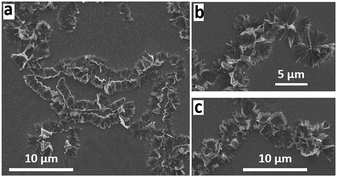
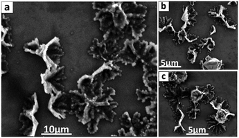
:![[thin space (1/6-em)]](https://www.rsc.org/images/entities/char_2009.gif) 2 ratio of o-xylene and DMF. The fractal like structures appear as if cones are fused together with their apexes oriented in the same direction. Similar structures are formed for higher rotational speeds, Fig. 2 and Fig. S1 (ESI†). The addition of DMF as the anti-solvent in the VFD is critical for the nucleation and growth of the cones, which is in high conversion, the material being isolated in ca. 82% yield. In the absence of VFD processing, a 1
2 ratio of o-xylene and DMF. The fractal like structures appear as if cones are fused together with their apexes oriented in the same direction. Similar structures are formed for higher rotational speeds, Fig. 2 and Fig. S1 (ESI†). The addition of DMF as the anti-solvent in the VFD is critical for the nucleation and growth of the cones, which is in high conversion, the material being isolated in ca. 82% yield. In the absence of VFD processing, a 1![[thin space (1/6-em)]](https://www.rsc.org/images/entities/char_2009.gif) :
:![[thin space (1/6-em)]](https://www.rsc.org/images/entities/char_2009.gif) 1 mixture of the two solutions mixed in a beaker, gave a non-uniform material of C60 in the fcc phase (Fig. S6, ESI†).
1 mixture of the two solutions mixed in a beaker, gave a non-uniform material of C60 in the fcc phase (Fig. S6, ESI†).
The dimensions of the particles and properties were studied using Scanning Electron Microscope (SEM), X-Ray Diffraction (XRD), Thermo-Gravimetric Analysis (TGA) and Raman spectroscopy. SEM was used to ascertain the size and shape of the material, without the necessity to coat them to impart conduction, as shown for the cones in Fig. 1, for different magnifications. Here samples of fullerene material were drop cast onto a silicon substrate as a colloidal suspension in hexane. A striking feature of the cones is their uniformity of shape, as symmetrical well defined right cones, although some of them have jagged upper edges, with tails radiating from a continuation of the flat cone surface. The origin of this is unclear but is likely to relate to the fluid flow associated with the mixing of the two liquids, and the time for onset of rapid nucleation and growth of the cones. The diameters, d, of the cones range from ca. 0.5 to 2.5 μm, with the wall thickness ranging from ca. 120 nm to 310 nm (average 215 nm) and pitch angle, α, 25° to 55° degrees (see Fig. 1).
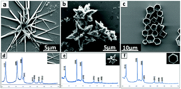
Following optimization of the conditions for fabricating fullerene C60 cones via mixing an o-xylene solution of C60 with DMF, we explored the micromixing of DMF with C60 solutions of other isomers of xylene as well as mesitylene. Distinctly different structures of self-assembled C60 are formed, Fig. 3 and Fig. S3 (ESI†), with no evidence for the formation of analogous self-assembled C60 cones. For m-xylene solutions of C60 mixed with DMF under the same conditions as for the formation of the cones, rod shaped particles formed, average diameter ca. 2.5 μm, ca. 4.80 μm to 7.60 μm length, Fig. 3a. Similarly, fullerene C60 dissolved in p-xylene formed uniform spicule like structures, diameter ca. 1.5 μm to 3.5 μm, Fig. 3b, and fullerene C60 dissolved in mesitylene formed hexagonal plates/prisms, approximately 1.2 μm to 2.3 μm in cross section, Fig. 3c. Thus under the conditions studied, the formation of the cones is specific to solutions of C60 in o-xylene being mixed with DMF.
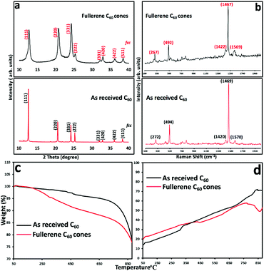
To further investigate the nature of the C60 assembled cones, Raman spectra (532 nm excitation) and XRD data were collected, for material formed under continuous flow mode at the optimal conditions, Fig. 4. The Raman spectra for the C60 cones have the signature vibrational modes for fullerene C60, Ag (1) at 492 cm−1 and Ag (2) at 1467 cm−1, and Hg at 267 cm−1 and 1569 cm−1.7 It is also evident in Fig. 4 that the position of the Raman bands for the C60 cones are within the spectral resolution of the grating used (600 g mm−1) when comparing the same bands for the as-received C60 material. The dominant band at 1467 cm−1 corresponds to the pentagonal pinch mode (Ag (2) mode) which is widely used as the analytical probe for electronic and structural properties for C60. The appearance of the Ag and Hg modes in our cone Raman spectra, and also the lack of a Raman band at 1458 cm−1 indicate that the C60 in the cones are pristine molecules. Any polymerisation of C60 ([2+2] cycloaddition)8,20 would result in a significant shift of the Ag (2) band to 1458 cm−1, and clearly this is not the case.
XRD patterns of C60 cones and as received C60 powder are in agreement, at least for the position of the peaks,4 for the fcc phase of the fullerene. After VFD processing, the material was collected by centrifugation, and washed with hexane and dried at 55 °C for 48 hours, prior to collecting the XRD data. Samples have a cell parameter a = 1.413 nm which corresponds to fcc C60, and thus the XRD is consistent with the lack of inclusion of any solvent, at least in the crystal lattice. This is in agreement with the formation of the nano-tubules of C60 from toluene and water.7 The major peaks at 10.8°, 17.7°, and 20.8°, correspond to the (111), (220), and (311) planes respectively for fcc C60.7 Overall, the XRD establishes the formation of fcc C60. However, the peaks are broad which arises from the presence of small crystals of fullerenes in the cones, with the Scherrer equation giving an average crystal domain size of 6.5 nm. This suggests that the primary process en route to the cones is the formation of these small nanoparticles, which are then assembled into the secondary cone structure. Such a mechanism is reminiscent of the formation of calcium carbonate via the initial formation of nano-particles of araganite.21 Further testimony to a two-step process in forming the cones is that at higher rotation speeds the cone structure distorts, with the formation of grooved fractal structures at 8.5k rpm, Fig. 2 and Fig. S2 (ESI†), which are also comprised of ca. 6 nm crystals of C60 in the fcc phase. We also note that rods, spicules and prims, Fig. 3, are also comprised of C60 domains of fcc C60, 6.1, 9.2 and 8.6 nm respectively.
The fullerene assembled cones are stable at room temperature over one month, with their thermal stability investigated using TGA under an atmosphere of nitrogen, and for comparison as received C60, with the results shown in Fig. 4c. Fullerene C60 does not show any mass loss up to 450 °C, but thereafter there is ca. 5% loss up to 750 °C, with a 25% mass loss from 750 to 880 °C, arising from sublimation of the fullerene. For the C60 assembled cones, there is a mass loss around 10% up to 450 °C which is consistent with the loss of included solvent molecules between self-assembled nanoparticles of fcc C60 (∼6.5 nm in diameter), associated with an amorphous component of the fullerene in the cones. There is gradual mass loss around 10% until 880 °C corresponding to the sublimation of C60. Fig. 4d displays the DSC curves for as received fullerene C60 and the cones, which are devoid of an exothermal peak corresponding to any reorganisation of the fullerenes in the cones. SEM of the material after heating the cones to 550 °C, Fig. 5, shows varying degrees of distortion of the original cones.
The formation of the C60 cones of fullerene arises from the high shear stress in the complex fluid dynamics in the thin film in the VFD.1,9 At 45° tilt angle, the liquid is accelerated up the tube and pulled down by gravity, and there is rotational speed induced pressure waves, resulting in intense micromixing between o-xylene containing C60 and DMF for which the fullerene is only sparingly soluble. After a systematic mapping of the parameters space of the VFD, we found that the optimised rotational speed of 4k rpm is critical in forming the C60 assembled cones. Increasing the rotational speed with other optimised parameters fixed, results in the distortion of the cones leading to grooved fractal structures (Fig. 2 and Fig. S1, S2, ESI†). Furthermore, replacing o-xylene with the other isomers of xylene and with mesitylene resulted in different morphologies (Fig. 3 and Fig. S3, ESI†).
In summary, we report a simple and effective method to fabricate cones of fullerene C60, as a new form of self-assembled fullerenes, under continuous flow mode of operation of the VFD microfluidic platform. The structure and the morphology of the cones were evaluated by SEM, XRD, Raman, TGA and DSC. The cones are rather uniform in shape, and importantly the isolated yield of the product is high, and the processing is scalable. We have established the ability to prepare 4.2 mg of the material for 40 mL of the two solutions passing through the VFD, and this can be extended out by increasing the volume of the liquid passing through the rotating tube and/or using a number of the relatively inexpensive VFDs in a parallel array.
Ibrahim K. Alsulami thanks King Abdulaziz College, Riyadh, Saudi Arabia, for scholarship funding, and the authors gratefully acknowledge financial support from the Australian Research Council and the Government of South Australia, and the Australian Microscopy & Microanalysis Research Facility (AMMRF) and the Australian National Fabrication Facility (ANFF) for accessing microscopic facilities.
Conflicts of interest
There are no conflicts to declare.Notes and references
- K. Vimalanathan and C. L. Raston, Adv. Mater. Technol., 2017, 2, 1600298 CrossRef.
- M. Prato, J. Mater. Chem., 1997, 7, 1097–1109 RSC.
- M. Sathish, K. i. Miyazawa, J. P. Hill and K. Ariga, J. Am. Chem. Soc., 2009, 131, 6372–6373 CrossRef PubMed.
- K. Miyazawa, Y. Kuwasaki, A. Obayashi and M. Kuwabara, J. Mater. Res., 2002, 17, 83–88 CrossRef.
- L. K. Shrestha, R. G. Shrestha, J. P. Hill and K. Ariga, J. Oleo Sci., 2013, 62, 541–553 CrossRef PubMed.
- R. G. Shrestha, L. K. Shrestha, A. H. Khan, G. S. Kumar, S. Acharya and K. Ariga, ACS Appl. Mater. Interfaces, 2014, 6, 15597–15603 CrossRef PubMed.
- K. Vimalanathan, R. G. Shrestha, Z. Zhang, J. Zou, T. Nakayama and C. L. Raston, Angew. Chem., Int. Ed., 2017, 56, 8398–8401 CrossRef PubMed.
- F.-Y. Hsieh, L. K. Shrestha, K. Ariga and S.-h. Hsu, Chem. Commun., 2017, 53, 11024–11027 RSC.
- B. Chen, M. Pawlik, R. Y. Tay, M. Zhu, M. Loeblein, S. H. Tsang and E. H. T. Teo, Carbon, 2018, 126, 464–471 CrossRef.
- Z. Zhang, A. Kutana, A. Roy and B. I. Yakobson, J. Phys. Chem. C, 2017, 121, 1257–1262 CrossRef.
- X. Chen, J. F. Dobson and C. L. Raston, Chem. Commun., 2012, 48, 3703–3705 RSC.
- J. Britton, K. A. Stubbs, G. A. Weiss and C. L. Raston, Chem. – Eur. J., 2017, 23, 13270–13278 CrossRef PubMed.
- X. Luo, A. H. M. Al-Antaki, K. Vimalanathan, J. Moffatt, K. Zheng, Y.-C. Zou, J. Zou, X. Duan, R. Lamb and S. Wang, React. Chem. Eng., 2018, 2, 164–170 RSC.
- L. Yasmin, X. Chen, K. A. Stubbs and C. L. Raston, Sci. Rep., 2013, 3, 2282 CrossRef PubMed.
- T. Z. Yuan, C. F. Ormonde, S. T. Kudlacek, S. Kunche, J. N. Smith, W. A. Brown, K. M. Pugliese, T. J. Olsen, M. Iftikhar and C. L. Raston, ChemBioChem, 2015, 16, 393–396 CrossRef PubMed.
- K. Vimalanathan, J. R. Gascooke, I. Suarez-Martinez, N. A. Marks, H. Kumari, C. J. Garvey, J. L. Atwood, W. D. Lawrance and C. L. Raston, Sci. Rep., 2016, 6, 22865 CrossRef PubMed.
- K. Vimalanathan, X. Chen and C. L. Raston, Chem. Commun., 2014, 50, 11295–11298 RSC.
- F. M. Yasin, R. A. Boulos, B. Y. Hong, A. Cornejo, K. S. Iyer, L. Gao, H. T. Chua and C. L. Raston, Chem. Commun., 2012, 48, 10102–10104 RSC.
- Y. A. Goh, X. Chen, F. M. Yasin, P. K. Eggers, R. A. Boulos, X. Wang, H. T. Chua and C. L. Raston, Chem. Commun., 2013, 49, 5171–5173 RSC.
- J. Geng, W. Zhou, P. Skelton, W. Yue, I. A. Kinloch, A. H. Windle and B. F. Johnson, J. Am. Chem. Soc., 2008, 130, 2527–2534 CrossRef PubMed.
- S. Von Euw, Q. Zhang, V. Manichev, N. Murali, J. Gross, L. C. Feldman, T. Gustafsson, C. Flach, R. Mendelsohn and P. G. Falkowski, Science, 2017, 356, 933–938 CrossRef PubMed.
Footnote |
| † Electronic supplementary information (ESI) available: Experimental details and characterisation results (Fig. S1–S6). See DOI: 10.1039/c8cc03730b |
| This journal is © The Royal Society of Chemistry 2018 |

