Efficient photocatalytic reduction of dinitrogen to ammonia on bismuth monoxide quantum dots†
Received
26th October 2016
, Accepted 13th November 2016
First published on 15th November 2016
Abstract
N2 reduction to ammonia by solar light represents a green and sustainable ammonia synthesis approach which helps to suppress the global warming and energy crisis. However, conventional semiconductors usually suffer from low activity or poor stability, largely suppressing the application of this technology. Here, we report that bismuth monoxide (BiO) quantum dots with an average size of 2–5 nm exhibited efficient photocatalytic activity for ammonia synthesis under simulated solar light. A highly efficient ammonia synthesis rate of 1226 μmol g−1 h−1 is achieved without the assistance of any sacrificial agent or co-catalyst, which is about 1000 times higher than that using the traditional Fe-TiO2 photocatalyst. Kinetic analysis reveals that the synergy of three low valence surface Bi(II) species markedly enhances N2 activation by electron donation, which finally resulted in the highly efficient N2 photoreduction performance. This work will shed light on designing efficient and robust N2 reduction photocatalysts.
Introduction
The reduction of dinitrogen (N2) to ammonia is a requisite transformation for life growth and survival.1–4 Although over 78% of the atmosphere is composed of dinitrogen molecules, they are not used by most of the organisms due to the strong N![[triple bond, length as m-dash]](https://www.rsc.org/images/entities/char_e002.gif) N bond, nonpolarity and high ionization potential.5,6 At present, most of the required nitrogen for human beings is still originated from the energy-intensive Haber–Bosch ammonia synthesis process,7,8 which consumes 1–2% of the world's energy supply and generates more than 300 million tons of carbon dioxide annually.9–12 In contrast, dinitrogen photoreduction to ammonia by solar light represents a green and sustainable ammonia synthesis route without fossil fuel consumption and CO2 emission.13–16 However, the state-of-the-art efficiencies for ammonia synthesis by this approach are still far away from the industrial demand.17–24
N bond, nonpolarity and high ionization potential.5,6 At present, most of the required nitrogen for human beings is still originated from the energy-intensive Haber–Bosch ammonia synthesis process,7,8 which consumes 1–2% of the world's energy supply and generates more than 300 million tons of carbon dioxide annually.9–12 In contrast, dinitrogen photoreduction to ammonia by solar light represents a green and sustainable ammonia synthesis route without fossil fuel consumption and CO2 emission.13–16 However, the state-of-the-art efficiencies for ammonia synthesis by this approach are still far away from the industrial demand.17–24
Generally, the rate-determining step for N2 reduction is cleavage of the NN bond.5,6 N2 activation by electron donation from some reducing active sites is indispensable for the promotion of NN bond cleavage,25 but such reducing active sites rarely exist on most of the semiconductor photocatalysts. Until now, the majority of the reported N2 photoreduction catalysts have only defect type activation centers,17–24 which result in unsatisfactory photocatalytic performance because of their limited defect concentrations. Besides, defect states often suffer from thermal instability and increased charge carrier recombination, which further prevent their practical application for artificial ammonia synthesis. Consequently, developing an ideal photocatalytic material which has a high concentration of non-defect type activation centers with robust stability holds the key to achieving a breakthrough in N2 photoreduction technology.
Using low valence metal species in low-valent metal oxide semiconductors for N2 activation may be a viable strategy to achieve this important goal. Low-valent metals in semiconductor solids have fewer coordination atoms than those in their high-valent state and are hence chemically unsaturated to facilitate chemisorption of molecules.26 Owing to the strong electron donating power, low-valent metal species such as Fe, Mo, Zr, and Ti have been widely studied for N2 activation in organometallic complexes,9,16,27–30 although a stoichiometric excess of strong reducing agents (such as Na, K) and extra proton sources are generally required to further generate NH3 in these reaction systems. Different from organometallic complexes, low-valent metal species in semiconductor materials may act as both N2 activation and hydrogenation centers without extra reducing agents, which allows quick reaction kinetics for N2 reduction, because the conduction band of a metal oxide semiconductor is usually hybridized by the metal p, d orbitals,31 and photogenerated electrons are mainly located on the metal sites. Moreover, different from defect-type active sites, lattice low-valent metal species can refrain from becoming an electron–hole recombination center and all of the surface low-valent metal sites could contribute to the catalysis reactions theoretically. In this regard, low-valent metal oxide semiconductors are expected to exhibit high photocatalytic activity for N2 photoreduction. To confirm this opinion, herein low valent bismuth monoxide (BiO) was selected as an ideal model material to study the N2 photoreduction performance. We focus on low valent bismuth(II) because it has high electron donating power and empty 6d orbitals for N2 adsorption and activation. More importantly, bismuth based materials have been widely studied with various catalytic applications.32–34
Experimental
Preparation of BiO
Firstly, sodium oleate (2.2 mmol) and Bi(NO3)3·5H2O (0.4 mmol) were successively added to distilled water (20 mL). After vigorous stirring for 2 h, 20 mL water was added and the suspension was then transferred to a 50 mL Teflon-lined autoclave, sealed and heated at 140 °C for 17 h. The system was then allowed to cool down to room temperature. The obtained solid products were collected by centrifugation, washed with absolute ethanol three times, and then freeze-dried for further characterization. For comparison, 0.2 wt% Fe-doped TiO2 was prepared according to a previous report by coprecipitation and calcination process at 500 °C for 3 h.18 The XRD pattern of the Fe-doped TiO2 is shown in Fig. S1.†
Characterization
The purity and crystallinity of the as-prepared samples were characterized by powder X-ray diffraction (XRD) on a Japan Rigaku Rotaflex diffractometer using Cu Kα radiation while the voltage and electric current were held at 40 kV and 100 mA. The transmission electron microscopy (TEM) analyses were performed using a JEOL JEM-2100F field emission electron microscope. X-ray photoelectron spectroscopy (XPS) was carried out by irradiating the sample with a 320 μm diameter spot of monochromated aluminum Kα X-rays at 1486.6 eV under ultrahigh vacuum conditions (performed on an ESCALAB 250, Thermo Scientific Ltd). The UV-vis diffuse reflectance spectrum (DRS) of the sample was recorded using a Hitachi UV-3010PC UV-vis spectrophotometer. The Fourier transform infrared (FTIR) spectrum of the concentrated ammonia product was obtained using a spectrophotometer (Nicolet 380, Thermo, USA). Nitrogen temperature-programmed desorption (N2-TPD) measurements were performed on a ChemiSorb 2750 instrument. Typically, 20 mg of the sample, placed in a glass tube, was pretreated by a He gas flow at 150 °C for 2 h, and then cooled down to 50 °C. The adsorption of N2 was performed in a 99.999% N2 gas flow for 2 h at 50 °C. After purging with He gas, the sample was heated from 50 °C to 450 °C at a rate of 10 °C min−1. The TPD signal was recorded using a thermal conductivity detector. All gas flow rates were set as 30 mL min−1 1H NMR spectra were acquired on a Bruker AV500 NMR spectrometer.
Photocatalytic test
Photocatalytic N2 reduction was performed using a 500 W Xe lamp located approximately 10 cm from the sample. The reaction cell (capacity 600 mL) was made of Pyrex glass with a quartz window on top. For atmospheric N2 fixation, 0.05 g of the as-prepared photocatalyst powder was dispersed in 200 mL deionized water and then stirred under the simulated solar light irradiation. For 15N isotopic labelling experiment, the reaction cell was enclosed by a quartz window on top. N2 (50% 15N2, 50% 14N2) gas was slowly bubbled through the reaction vessel, which contained 200 mL deionized water until it was saturated. Then the reaction vessel was sealed and irradiated under the simulated solar light irradiation. During the photocatalytic tests, the temperature of the reaction vessel was maintained at 25 °C by providing a flow of cooling water. The concentration of ammonia in the reactor solution was measured using the indophenol blue method. The amount of evolved O2 was determined by using online gas chromatography.
Computational methods
Periodic density functional theory (DFT) calculations with spin-polarization were performed using the VASP code. The non-local exchange and correlation energies were described using a generalized gradient approximation with the Perdew–Burke–Ernzerhof (PBE) functional (PBE-GGA). The electron–ion interactions were described by the projector augmented wave (PAW) potential. The plane wave-plane basis set with an energy cutoff of 400 eV and 4 × 4 × 4 k-point Monkhorst–Pack grid were used in our calculations. The convergence criteria for electronic SCF and force were set as less than 1.0 × 10⁻⁶ eV and 0.01 eV Å−1, respectively.
Electrochemical measurements
Electrochemical measurements were performed on a CHI 660D electrochemical workstation (Shanghai Chenhua, China) using a standard three-electrode cell with a working electrode, a platinum wire as the counter electrode, and a standard saturated calomel electrode (SCE) in saturated KCl as the reference electrode. The working electrodes were prepared by dip-coating: briefly, 5 mg of the photocatalyst was suspended in 0.1 mL of ethanol in the presence of 1% Nafion to produce a slurry, which was then dipcoated onto a 2 cm × 1.5 cm FTO glass electrode and dried at 25 °C.
Calculation of electron transfer number
For an adsorption-controlled and irreversible electrode process, according to Laviron,35Ep is defined by the following equation:
Ep = E0 + (RT/anF)ln(RTk0/anF) + (RT/anF)ln![[thin space (1/6-em)]](https://www.rsc.org/images/entities/char_2009.gif) v v |
where R is the molar gas constant, T is the thermodynamic temperature, F is the Faraday constant, a is the transfer coefficient, k0 is the standard rate constant of the reaction, n is the electron transfer number involved in the rate-determining step, ν is the scan rate (mV s−1), and E0 is the formal potential. For an irreversible electrode process, a≈0.5.
Results and discussion
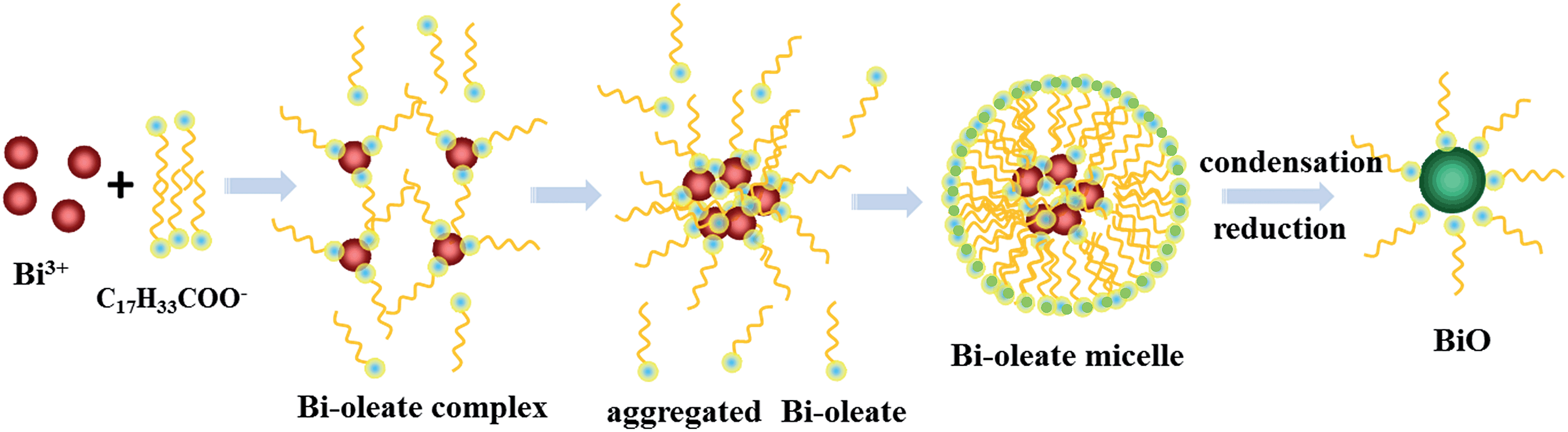
We designed an oleate-modified hydrothermal synthesis method to obtain the desired BiO material. Oleate ions played an important role in the formation of this low-valence bismuth oxide compound, as shown in Fig. 1. Initially each Bi3+ ion interacted electrostatically with three oleate ions to form Bi–oleate complexes, which then aggregated into larger Bi–oleate particles driven by the hydrophobic effect of the oleate tails. The presented extra oleate ions in the solution accumulated around the Bi–oleate complex by means of hydrophobic carbon tails to form stable Bi–oleate micelles with a hydrophilic outer shell which dispersed homogeneously in the reaction solution. The BiO compound was nucleated through a dehydration and condensation reaction after permeation of a small amount of OH− into the Bi–oleate micelles. This process was hindered by the strong steric effect from oleate, which has a long aliphatic carbon chain to prevent the entry of polar ions. Owing to the reductivity of unsaturated carbon–carbon double bonds in oleate, Bi(III) was gradually reduced to Bi(II) during reaction with OH− to form the low-valence BiO compound in the micelles. Without the addition of oleate ions, Bi2O3 is the final hydrothermally synthesized product. The as-prepared BiO compound exhibited quantum sized spherical-like morphology (quantum dots) with an average size of 2–5 nm (Fig. 2a). A high magnification TEM image (Fig. 2b) gives more details of the microstructure, which revealed the single crystal nature of the BiO particles. From the high resolution TEM (HRTEM) image in Fig. 2c, (003) and (100) planes of BiO (space group R3m) with a d spacing of 0.325 and 0.336 nm were clearly observed, which belong to the [010] zone axis of BiO. The schematic crystal structure of BiO along the [010] direction (Fig. 2d) displayed the same orientation and arrangement of (003) and (100) planes as that observed from Fig. 2c. The purity and crystallinity of the BiO particles were investigated using X-ray diffraction patterns. As shown in Fig. 2e, all of the diffraction peaks can be indexed to the hexagonal phase of BiO (JCPDS no. 27-0054). No other likely impurities, such as Bi2O3 or Bi(OH)3, were detected. The broad diffraction peaks were ascribed to its quantum size which is calculated to be about 3 nm in average based on the Scherrer equation. The XPS spectrum further confirmed the presence of this low-valent bismuth(II) monoxide compound. As shown in Fig. 2f, the binding energies of Bi 4f5/2 and Bi 4f7/2 peaks of the original BiO surface are mainly located at 164.55 eV and 159.26 eV which originate from the residual surface-adsorbed Bi(III)–oleate precursor. However, in the case of an etched surface, the binding energies of the Bi 4f5/2 and Bi 4f7/2 peaks mainly decreased to 162.35 eV and 156.95 eV, proving the existence of low-valent bismuth species on a cleaner BiO surface. The optical absorption property of the prepared BiO was investigated by UV-vis diffuse reflectance spectroscopy which exhibited an intense UV-vis light absorption at wavelengths shorter than 430 nm (Fig. S2†), indicating a band gap of 2.88 eV for the BiO sample.
 |
| | Fig. 1 Schematic illustration of the whole synthesis procedure for the BiO quantum dots. | |
 |
| | Fig. 2 Characterizations of the hydrothermally synthesized BiO sample. (a) Low magnification TEM image of the BiO sample. (b) High magnification TEM image. (c) High resolution TEM image. (d) The related schematic atomic model of BiO, clearly showing the atomic configuration of Bi/O and the hexagonal tunnel structure along the [010] direction. (e) XRD pattern of the as-prepared BiO sample. (f) XPS spectrum of the as-prepared BiO sample in the Bi 4f5/2 and Bi 4f7/2 binding energy region. | |
To study the photocatalytic N2 reduction property of the BiO catalyst, 0.05 g of the BiO particles was dispersed in 200 mL of deionized water and then subsequently irradiated under simulated solar light irradiation. Control experiments showed that NH4+ cannot be generated in the absence of the BiO catalyst or solar light irradiation. In contrast, simulated solar light irradiation resulted in continuous ammonia generation by the BiO sample (Fig. 3a). After 24 h of irradiation, the BiO catalyst generated 7.4 mg L−1 of NH4+ from pure water in air. In an acidic reaction solution (pH 3.8) which could provide excess protons to decrease the kinetic barrier for N2 reduction, the generated ammonia concentration by the BiO catalyst was increased to 20.6 mg L−1 within 24 h, with a much improved ammonia synthesis rate of about 1226 μmol g−1 (catalyst) h−1, 1000 times higher than that of the traditional Fe-TiO2 photocatalyst (Fig. 3a) under the same conditions. When the reaction was performed in 15% aqueous methanol, a known sacrificial electron donor, the ammonia synthesis rate was further significantly improved, producing a total NH4+ amount of 0.7 mmol after 24 h (Fig. 3b), equivalent to a turnover number of 3.18. This suggests that ammonia evolution under these conditions is catalytic. The increase in the ammonia synthesis rate in aqueous methanol indicates that the BiO quantum dots are able to photooxidize methanol. Under the same conditions, no ammonia generation was detected with the BiO catalyst both in pure water and aqueous methanol in argon saturated solution, indicating that the ammonia in the reaction system originated from N2 reduction. The stability of the BiO catalyst under acidic conditions was also investigated. After 5 consecutive runs (120 h) for N2 reduction, the photocatalytic performance of the BiO particles was well-maintained (Fig. 3c). The TEM image of the BiO catalyst after the cycle of reaction also indicates the stability of the BiO catalyst (Fig. S3†).
 |
| | Fig. 3 Photocatalytic N2 reduction performance of the as-prepared BiO sample under different conditions and simulated solar light irradiation. (a) The generated ammonia concentrations at different irradiation times in pure water; inset: the corresponding ammonia synthesis rate. (b) The generated ammonia concentrations at different irradiation times in 15 vol% methanol solution. (c) Photostability of the as-prepared BiO sample for N2 reduction under simulated solar light and acidic conditions (pH 3.8). (d) Comparison of experimental infrared spectra of NH4+ obtained after N2 photoreduction on the BiO catalyst using 50% 15N2 labelled N2 and pure 14N2 respectively. | |
To further confirm that the detected NH4+ in our experiment indeed originated from N2 reduction, we performed an isotopic labelling study using 50 vol% 15N2 as the purge gas. Infrared spectroscopy was used to characterize the NH4+ product. The IR spectra (Fig. 3d) indicate that both 15NH4+ and 14NH4+ exist in the reaction solution when using 50% 15N2 labelled N2, while only 14NH4+ is detected when using pure 14N2. The infrared absorption peak of 14NH4+ was located around 1405 cm−1, while the peak position for 15NH4+ is at 1358 cm−1 which is in good agreement with the value estimated according to the isotope effect (that is, 1405 cm−1 × (14/15)1/2 = 1357 cm−1).25 The isotope labelling study further proved that the NH4+ originates from the photocatalytic N2 reduction process. 1H NMR spectrum was also used for detecting the 15NH4+ species in the obtained ammonia product. As shown in Fig. S4,† both 15NH4+ and 14NH4+ were observed in the NMR spectrum. The ratio of the 15NH4+ content to 14NH4+ was about 2.7:3, which is close to the initial 15N2 ratio.
It is of significant importance to understand the underlying mechanism of the high photocatalytic activity of BiO in reducing N2 in order to develop other efficient photocatalysts. Quantum chemical calculations based on density functional theory (DFT) were conducted to investigate the possible N2 activation and hydrogenation process on the BiO catalyst. According to the experimental observation from the HRTEM image, a representative BiO {010} surface was selected to investigate the N2 activation and hydrogenation performance. First, the partial charge density of the nearby Fermi level was calculated to analyze the possible interaction positions of BiO surfaces with N2. As shown in Fig. 4a and b, the valence bands of BiO near Fermi levels are mainly generated by p-electrons of Bi atoms. The charge distribution on BiO {010} surface is significantly localized and accumulated around Bi atoms, which indicates that N2 activation by electron donation may take place upon the Bi activation centers. The extent of N2 activation and hydrogenation on the BiO surface is reflected by the change of the N–N bond length. Fig. 4c presents N–N bond distance evolutions with addition of hydrogen atoms on the BiO {010} surfaces. For comparison, the corresponding evolutions without the catalyst are also plotted. As shown in Fig. 4c, the BiO {010} surface displays high catalytic activity on activation of the NN bond in N2Hn (n = 0–3). The N–N bond length could be elongated from 1.09 Å to 1.12 Å when it is near the BiO {010} surface. The N–N bond length could be further increased along with hydrogenation until three H atoms were hydrogenated, indicating that the NN bond may be broken after three H atoms were added by the BiO catalyst. Considering that the N2 photoreduction experiment was performed in water in this study, the influence of water molecules on the N2 activation and hydrogenation was also investigated. The calculated result indicates that the catalytic activity of BiO was not changed with addition of H2O on the surface. In addition, H2O molecules covering the surface can quickly dissociate into H+ and OH−, providing sufficient hydrogen for ammonia generation. Besides, the binding energy calculations reveal a weaker interaction between N2Hn and the water-covered BiO surface than that on a dry surface (Fig. 4d). This indicates that water on the BiO {010} surface is advantageous to improve N2 photoreduction performance since hydrogenated N2Hn can easily be desorbed from the catalyst. Temperature programmed desorption (TPD) investigation was also conducted to visualize the adsorption and activation of N2 on the surface of the BiO catalyst. As shown in Fig. S5,† two peaks at 295 °C and 330 °C were clearly observed for N2 desorption, which indicated the excellent N2 chemisorption on the BiO catalyst.
 |
| | Fig. 4 Quantum chemical calculations of N2 activation and hydrogenation performance of the BiO catalyst based on density functional theory. (a and b) The calculated charge density plot at the valence band maximum (VBM) of BiO {010} surfaces; a: top view and b: side view. The yellow and blue isosurfaces represent charge accumulation and depletion in the space, respectively. (c) The N–N bond distance evolutions with addition of hydrogen atoms on BiO {010} surface. (d) The binding energy of N2Hn on BiO {010} surface. | |
Photoelectrochemical measurements further revealed the possible reasons for the high performance of the BiO catalyst. As shown in Fig. 5a, two well-defined cathodic peaks around −0.7 V and −1.2 V appear in the cyclic voltammetry experiments in N2 saturated 0.5 M Na2SO4 solution for the BiO electrode in an acidic solution (pH = 3.8), the pH value of which was adjusted using dilute H2SO4. The lower reduction peak around −0.7 V arises only after the electro-reduction process proceeds for a certain length of time (Fig. 5a and S6†), indicating that this reduction peak may have originated from further reduction of intermediates during the photoelectrochemical process. Therefore the N2 reduction peak around −1.2 V (Ep) was adopted for the kinetic study under acidic conditions. As shown in Fig. 5a, the peak current densities increased with increase in the scan rates (ν). The electron transfer number (n) involved in the N2 reduction can be calculated from the slope of Ep − lnν. The value of n was calculated to be 2.93 at the potential of 20–100 mV, indicating that a possible one-step three electron transfer N2 reduction process may occur on the BiO surface. As is well known, nitrogen fixation is a proton-coupled reaction.36 Although the BiO surface could provide sufficient low valence Bi(II) activation centers, excess H+ is also important to realize a proton coupled multi-electron reduction process. In a neutral reaction solution, the electron transfer number was decreased to 1.34 based on the analysis of the reduction peak around −0.9 V (Fig. 5b), indicating that N2 reduction on the BiO catalyst in neutral solution may be realized through six consecutive one-electron redox steps, resulting in a much lower ammonia synthesis rate. This is in line with the observed lower photocatalytic N2 reduction activity at pH = 7. Besides, a decreased cathodic current density (Fig. 5c) in a N2-saturated reaction system was observed when compared with that in air saturated solution, which proved that a larger number of electrons were transferred from the BiO catalyst to the N2 molecule in the N2-saturated reaction system under the same conditions. Fig. 5d shows the Mott–Schottky spectrum of the BiO sample, which is usually used for the analysis of the flat band potential (Efb) of semiconductor electrodes.37 The positive slope of the plot indicates that the BiO catalyst is an n-type semiconductor with electrons as the majority charge carriers. The Efb value which was calculated from the intercept of the axis with potential values was at −0.69 V vs. SCE. For many n-type semiconductors, Efb is considered to be about 0.1 V below the conduction band (Ecb).38 Based on this, the estimated Ecb value of the BiO sample was −0.55 V vs. NHE. According to the thermodynamic data of N2H3 reported by Bauer,39 the N2 reduction potential via N2 + 3H+ + 3e− → N2H3 is not larger than −0.485 V vs. NHE. This indicates that the photogenerated electrons in the BiO catalyst could energetically reduce the N2 molecule via a proton-coupled three-electron reduction process. Besides, the valence band potential of the BiO catalyst, which was estimated from the band gap and Ecb, was also energetically large enough (2.39 V vs. NHE) for water oxidation (1.23 V vs. NHE) under acidic conditions, indicating that water could efficiently act as a sacrificial electron donor for ammonia generation. All of these studies proved the possibility of a highly efficient one-step three-electron N2 reduction on the BiO catalyst, which may be realized by the synergy of three adjacent low valence Bi(II) activation centers. This process does not occur easily in a traditional N2 reduction photocatalyst, which only has isolated defect-type activation centers.
 |
| | Fig. 5 Kinetic study of N2 reduction on the BiO catalyst by electrochemical measurements in N2 saturated 0.5 M Na2SO4 under room temperature (25 °C) and simulated solar light irradiation. (a) Cyclic voltammograms of the BiO electrode at pH = 3.8. (b) Cyclic voltammograms of the BiO electrode at pH = 7. Inset: plot of reduction peak potential (Ep) vs. lnν (scan rate). (c) Cathodic electrochemical scans on the as-prepared BiO electrode under chopped simulated solar light irradiation. (d) Mott–Schottky plot of the as-prepared BiO electrode in 0.5 M Na2SO4 at pH = 7. | |
The crystal structure and coordination environment of the BiO compound may play an important role in its highly efficient photocatalytic N2 reduction performance. As shown in Fig. 2d, the BiO compound exhibits a hexagonal tunnel structure along the [010] direction, which is built up from three alternately arranged Bi groups and O groups. The entrance diameter of this tunnel structure is about 4.4–4.7 Å, large enough for structurally filling one N2 molecule (diameter 3 Å). A careful observation of the local structure of BiO indicates that BiO4 presents a pyramidal unit with two ∠OBiO angles of 114.2° and 104.2°, far from a tetrahedral structure (Fig. S7†). This indicates that bismuth atoms may undergo an orbital hybridization of sp3d resulting in the orbital distribution of a trigonal bipyramid, leaving a lone pair of electrons on the Bi atom. The N2 molecule may be stretched and activated by three alternatively arranged Bi atoms through donating electrons to the empty 6d orbitals of Bi atom and accepting electrons from the lone pairs of Bi atom to its three unoccupied anti-bonding orbitals (π*2py, π*2pz and σ*2px), resulting in a 1N2–3Bi side-on bond structure (Fig. 6a). The electron donations from the three adjacent low valence bismuth ions will strongly weaken the NN bond, which facilitates a one-step three electron N2 reduction process in a successive photocatalytic process by proton and electron transfer (Fig. 6b).
 |
| | Fig. 6 Possible pathway for N2 activation and hydrogenation on the BiO catalyst. (a) Schematic electron donation from the lone pairs of three Bi atoms to the three unoccupied anti-bonding orbitals (σ*2px, π*2py, and π*2pz) of the N2 molecule, forming a 1N2–3Bi(II) side-on bond structure. (b) The whole N2 activation and reduction process on the BiO catalyst. | |
Based on the above analysis, the possible N2 reduction reactions on BiO surface under acidic conditions are proposed as follows.
| | | BiO + hv → BiO (h+ + e−) | (1) |
| | | N2 + 3BiO (e−) + 3H+ → N2H3 | (2) |
| | | N2H3 + 3BiO (e−) + 5H+ → 2NH+4 | (3) |
| | | N2H3 + BiO (e−) + H+ → N2H4 | (4) |
| | | 3H2O + 6BiO (h+) → 3/2O2 + 6H+ | (6) |
First, simulated solar light excited electrons and holes are generated on the BiO catalyst (eqn (1)). Then the photogenerated electrons may transfer to the surface and participate in a one-step three electron N2 reduction process to obtain an N2H3 intermediate (eqn (2)) due to the possible 1N2–3Bi side-on bond structure. The N2H3 intermediate will be further reduced to NH4+ (eqn (3)) or N2H4 (eqn (4)) by a subsequent one step three-electron or one-electron photocatalytic reduction process, respectively. Otherwise, the N2H3 intermediate will be decomposed, because it is a short-lived, endothermic compound.39,40 If the N2H3 intermediate is not further reduced, it will decompose into N2 and H2 spontaneously (eqn (5)). In our experiment, the reaction rates of eqn (2) and (3) may be much higher than that of eqn (5), resulting in continuous production of NH4+ under the acidic conditions. The amount of N2H4 in the final product was only about 1.6%, possibly because of the 1N2–3Bi side-on coordinating mode of N2 which facilitates the three-electron reduction process (eqn (2) and (3)). During the photocatalytic N2 reduction process, O2 was produced from water oxidation by photogenerated holes (eqn (6)). The theoretical molar ratio of the generated NH4+ to O2 from the above equations is 1.33. In a closed reaction system filled with pure N2 and water, we observed continuous O2 evolution (Fig. S8†) along with prolonged irradiation time and a total amount of 117 μmol O2 was obtained when generating 2.32 mg NH4+. The molar ratio of the generated NH4+ to O2 is 1.41, which is close to the theoretical value. Besides, a tiny amount of H2 (2.4 μmol) was also detected within 24 h in the closed reaction system, which may have originated from the decomposition of a trace amount of the unconverted N2H3 intermediate.
Conclusions
In summary, bismuth monoxide quantum dots were successfully synthesized by a facile hydrothermal synthesis method using oleate as the capping agent. Different from the other previously reported N2 reduction photocatalysts which have limited and randomly distributed defect-type N2 activation centers, the BiO catalyst has all of the lattice bismuth species as potential activation centers. This characteristic makes the as-synthesized BiO a highly efficient photocatalyst for solar N2 reduction to ammonia. The ammonia synthesis rate is up to 1226 μmol g−1 h−1 without the assistance of any sacrificial agent or co-catalyst, which is about 1000 times higher than that of the previously reported traditional Fe-TiO2 photocatalyst. More importantly, the photocatalytic activity does not show obvious deactivation even after 120 h. Kinetic studies by electrochemical measurements and quantum chemical calculations indicate that the highly improved photocatalytic performance of BiO may be ascribed to the synergy of the three low valence surface Bi(II) species for N2 activation. This study may open up new opportunities for designing highly efficient and robust solar light photocatalysts for artificial ammonia synthesis under ambient conditions.
Acknowledgements
This work was financially supported by the National Basic Research Program of China (2013CB933200), National Natural Science Foundation of China (21671197, 51272269, 51272303, 51472260), and the research grant (16ZR1440800) from Shanghai Science and Technology Commission. Prof. Guangyu Li from Shanghai Institute of Organic Chemistry is gratefully acknowledged for measurement and interpretation of the NMR data.
References
-
T. Rosswall, in Some Perspectives of the Major Biogeochemical Cycles, ed. G. E. Likens, Wiley, New York, 1981, Ch. 2 Search PubMed.
- J. B. Howard and D. C. Rees, Chem. Rev., 1996, 96, 2965–2982 CrossRef CAS PubMed.
- B. M. Hoffman, D. R. Dean and L. C. Seefeldt, Acc. Chem. Res., 2009, 42, 609–619 CrossRef CAS PubMed.
- R. Navarro-González, C. P. McKay and D. N. Mvondo, Nature, 2001, 412, 61–64 CrossRef PubMed.
- S. Gambarotta and J. Scott, Angew. Chem., Int. Ed., 2004, 43, 5298–5308 CrossRef CAS PubMed.
- A. J. Pool, E. Lobkovsky and P. J. Chirik, Nature, 2004, 427, 527–530 CrossRef PubMed.
-
V. Smil, Enriching the Earth: Fritz Haber, Carl Bosch and the Transformation of World Food Production, MIT Press, Cambridge, MA, 2001 Search PubMed.
- C. Sivasankar, S. Baskaran, M. Tamizmani and K. Ramakrishna, J. Organomet. Chem., 2014, 752, 44–58 CrossRef CAS.
- R. Schlögl, Angew. Chem., Int. Ed., 2003, 42, 2004–2008 CrossRef PubMed.
- H. Bielawa, O. Hinrichsen, A. Birkner and M. Muhler, Angew. Chem., Int. Ed., 1999, 40, 1061–1063 CrossRef.
- T. Shima, S. Hu, G. Luo, X. Kang, Y. Luo and Z. Hou, Science, 2013, 340, 1549–1552 CrossRef CAS PubMed.
- Y. Tanabe and Y. Nishibayashi, Coord. Chem. Rev., 2013, 257, 2551–2564 CrossRef CAS.
- G. N. Schrauzer and T. D. Guth, J. Am. Chem. Soc., 1977, 99, 7189–7193 CrossRef CAS.
- E. Endoh, J. K. Leland and A. J. Bard, J. Phys. Chem., 1986, 90, 6223–6226 CrossRef CAS.
- H. Li, J. Shang, Z. Ai and L. Zhang, J. Am. Chem. Soc., 2015, 137, 6393–6399 CrossRef CAS PubMed.
- H. Kisch, Angew. Chem., Int. Ed., 2013, 52, 812–847 CrossRef CAS PubMed.
- V. Augugliaro, A. Lauricella, L. Rizzuti, M. Schiavello and A. Sclafani, Int. J. Hydrogen Energy, 1982, 7, 845–850 CrossRef CAS.
- J. Soria, J. C. Conesa, V. Augugliaro, L. Palmisano, M. Schiavello and A. Sclafani, J. Phys. Chem., 1991, 95, 274–282 CrossRef CAS.
- O. P. Linnik and H. Kisch, Mendeleev Commun., 2008, 18, 10–11 CrossRef CAS.
- L. Palmisano, V. Augugliaro, A. Sclafani and M. Schiavello, J. Phys. Chem., 1988, 92, 6710–6713 CrossRef CAS.
- K. Tennakone, S. Punchihewa and R. Tantrigoda, Sol. Energy Mater., 1989, 18, 217–221 CrossRef CAS.
- O. Rusina, A. Eremenko, G. Frank, H. P. Strunk and H. Kisch, Angew. Chem., Int. Ed., 2001, 40, 3993–3995 CrossRef CAS.
- W. Zhao, J. Zhang, X. Zhu, M. Zhang, J. Tang, M. Tan and Y. Wang, Appl. Catal., B, 2014, 144, 468–477 CrossRef CAS.
- G. Dong, W. Hob and C. Wang, J. Mater. Chem. A, 2015, 3, 23435–23441 CAS.
- M. Kitano, Y. Inoue, Y. Yamazaki, F. Hayashi, S. Kanbara, S. Matsuishi, T. Yokoyama, S. W. Kim, M. Hara and H. Hosono, Nat. Chem., 2012, 4, 934–940 CrossRef CAS PubMed.
- G. Ertl, Angew. Chem., Int. Ed., 2008, 47, 3524–3535 CrossRef CAS PubMed.
- M. M. Rodriguez, E. Bill, W. W. Brennessel and P. L. Holland, Science, 2011, 334, 780–783 CrossRef CAS PubMed.
- K. Arashiba, Y. Miyake and Y. Nishibayashi, Nat. Chem., 2011, 3, 120–125 CrossRef CAS PubMed.
- B. A. MacKay and M. D. Fryzuk, Chem. Rev., 2004, 104, 385–401 CrossRef CAS PubMed.
- A. Caselli, E. Solari, R. Scopelliti, C. Floriani, N. Re, C. Rizzoli and A. Chiesi-Villa, J. Am. Chem. Soc., 2000, 122, 3652–3670 CrossRef CAS.
- K. Maeda, T. Takata, M. Hara, N. Saito, Y. Inoue, H. Kobayashi and K. Domen, J. Am. Chem. Soc., 2005, 127, 8286–8287 CrossRef CAS PubMed.
- S. Sun, W. Wang, D. Li and L. Zhang, ACS Catal., 2014, 4, 3498–3503 CrossRef CAS.
- J. Medina-Ramos, J. L. DiMeglio and J. Rosenthal, J. Am. Chem. Soc., 2014, 136, 8361–8367 CrossRef CAS PubMed.
- L. Liang, F. C. Lei, S. Gao, Y. F. Sun, X. C. Jiao, J. Wu, S. Qamar and Y. Xie, Angew. Chem., Int. Ed., 2015, 54, 13971–13974 CrossRef CAS PubMed.
- E. Laviron, J. Electroanal. Chem. Interfacial Electrochem., 1974, 52, 355–393 CrossRef CAS.
- L. Pospíšil, J. Bulíčková, M. Hromadová, M. Gál, S. Civiš, J. Cihelka and J. Tarábek, Chem. Commun., 2007, 2270–2272 RSC.
- A. Watanabe and H. Kozuka, J. Phys. Chem. B, 2003, 107, 12713–12720 CrossRef CAS.
- Y. Matsumoto, J. Solid State Chem., 1996, 126, 227–234 CrossRef CAS.
- N. Bauer, J. Phys. Chem., 1960, 64, 833–837 CrossRef CAS.
- B. Ruscic and J. Berkowitz, J. Chem. Phys., 1991, 95, 4378–4384 CrossRef CAS.
Footnote |
| † Electronic supplementary information (ESI) available: Fig. S1–S8. See DOI: 10.1039/c6ta09275f |
|
| This journal is © The Royal Society of Chemistry 2017 |
Click here to see how this site uses Cookies. View our privacy policy here. 
 Open Access Article
 This Open Access Article is licensed under a Creative Commons Attribution-Non Commercial 3.0 Unported Licence
 *a,
Ling
Zhang
a,
Jianjun
Liu
*a and
William A.
Goddard III
b
*a,
Ling
Zhang
a,
Jianjun
Liu
*a and
William A.
Goddard III
b