
Membrane-less photoelectrochemical cells: product separation by hydrodynamic control†
Isaac
Holmes-Gentle
 a,
Franca
Hoffmann
b,
Camilo A.
Mesa
c and
Klaus
Hellgardt
*a
a,
Franca
Hoffmann
b,
Camilo A.
Mesa
c and
Klaus
Hellgardt
*a
aDepartment of Chemical Engineering, Imperial College London, London, SW7 2AZ, UK. E-mail: k.hellgardt@imperial.ac.uk
bFaculty of Mathematics, University of Cambridge, Cambridge, UK
cDepartment of Chemistry, Imperial College London, London, SW7 2AZ, UK
First published on 18th April 2017
Abstract
A key step in order to realise photo-electrochemical (PEC) water splitting to produce hydrogen sustainably, is reactor design. Good engineering will minimise energy losses (both optical and ohmic) due to reactor construction, whilst ensuring the H2 and O2 produced are separated, and this can subsequently relax the requirements on the photo-absorber material and/or electro-catalysts. In this paper we show that separation of the products through hydrodynamic flow alone would negate the need for the conventionally used membrane, which has an associated ohmic drop and cost. This is demonstrated to be possible using a ‘laminar flow between two parallel plates’ reactor design and AR/Pe and AR are found to be the two key dimensionless numbers that predict product cross-over (where AR, Pe are aspect ratio and Péclet number respectively). Supersaturation was used as an indicator of bubble formation, which disrupts the laminar flow required for separation and it is shown that by increasing the reactor pressure, higher current densities can be tolerated before supersaturation occurs. Removal of the dissolved hydrogen and oxygen from electrolyte is discussed. A multi-physics model, which employs an optical transfer matrix method, is used to validate the previous conclusions. Experimental data for hematite and Pt deposited on FTO was used as the anode and cathode respectively. Parasitic optical losses and efficiency improvement with stacking are shown for the example reactor configuration. Additionally, the concept of stacking this reactor design in order to absorb light in multiple passes is introduced. This approach relaxes a classical constraint on photo-absorber materials: large absorption length compared to small diffusion length of charge carriers in the semiconductor.
1 Introduction
Substantial efforts around the world are underway to develop materials and devices to convert solar energy directly into fuels, employing photo-electrochemical (PEC) systems.1,2 A key driver of this is the need for storage of solar energy in chemical bonds in order to address the issue of intermittency of energy production.2 Solar fuels produced by PEC systems are one pathway to produce a zero carbon emission energy vectors such as hydrogen for domestic and transportation purposes.3,4Since its first demonstration by Fujishima and Honda,5 there have been significant breakthroughs in the performance of systems, which can photo-electrochemically reduce water to produce H2.6 Nevertheless, solar fuels have been constrained from commercialisation by many technological, economic and political considerations. One major factor for this is that the perfect photo-absorber, which can satisfy the commercial requirements of cost, performance and longevity whilst also meeting scientific challenges of ensuring successful charge separation, significant absorption of the solar spectrum and an optimal band gap position, is yet to emerge.6,7 Hence the solar fuels field has been dominated the search for new ‘holy grail’ materials and the improvement of existing sub-optimal photo-absorbers.
A somewhat smaller body of work has concentrated on the reactor design suitable for scaled up systems. The reactor should be engineered to meet the following technological requirements: (1) successful removal and separation of products (H2 and O2) (2) resistive losses between electrodes (through solution and/or membrane) minimised (3) minimise parasitic optical losses and maximise solar collection.8 Product separation is most commonly achieved using an ion permeable membrane between electrodes. However this has significant disadvantages such as appreciable ohmic losses9 (particularly in alkaline systems, which have a low conductivity10) and significant costs.11,12 The placement of the membrane within the cell is further constrained by the compromise between reducing the average path length of ions between electrodes, minimising current density distribution and not blocking light from being absorbed. There have been a number of novel examples in order to get round these issues such as a louvered-design13 or perforated photo electrode.14,15 Another typical compromise is in the thickness of the membrane, where the energy loss due to ionic conduction is balanced against the gas cross-over.16
Membrane-less reactor design replaces the compromises associated with membrane placement and cost with a new challenge: successful product separation and safe operation of the cell and hence complete and scalable examples for membrane-free design for photo-electrochemical cells have not been investigated in depth. One notable example of a membrane-less PEC system that employs bubble buoyancy as the method of product removal suffered untenable levels of product cross-over.17 A more complete investigation into electrochemical devices, which utilise forced convection hydrodynamics, is underway with example applications ranging from electrolysers18,19 to fuel cells/redox batteries.20–25 To the best of our knowledge, there has been no application of this membrane-less technology to solar fuel processes.
Mass-transfer control through manipulation of the hydrodynamics might be more facile for PEC devices than electrolysers due to typical operational current densities being an order or multiple orders of magnitude lower.9 This is due to the fact that the current density in a PEC device is proportional to the power intensity of light and this is limited by the solar resource. The use of optics to concentrate the sunlight increases this current density limit, but there is a feasible limit to solar concentration due to optical losses and cost. The feasibility of designs that use low level concentration such as 10× sun have been investigated.26,27 To conclude, the low current densities inherently involved in solar driven PEC systems make it an obvious candidate for investigation into evolved product separation by hydrodynamic control.
The theoretical performance of PEC reactors designs are assessed through modelling and simulation and this subsequently helps guide innovation in scalable designs. Kemppainen et al.28 have produced an extensive review on modelling PEC reactors and there are examples that range from fundamental models of charge transport in the semiconductor29,30 and both semiconductor and electrolyte,31 to large scale models of devices.13,26,32,33 Crucially, all the large scale device models (with the exception of Jin et al.17) included a membrane for product separation and hence the theoretical benefits of applying membrane-less electrolyser research to PEC systems have not been assessed.
In this work, we propose a membrane-less PEC reactor design and investigate the fundamental behaviour of this to quantify the operational parameters required for successful operation. We then develop a multi-physics model, which includes the optical absorption, current density distribution within the cell and the mass transfer of evolved products, for an example PEC system.
2 Proposed design and theory
2.1 Hydrodynamic product separation
Outlined here is a novel design of PEC cell that is designed to keep the evolved hydrogen and oxygen from mixing via control of the fluid mechanics in the system. Forced convection through the cell ensures that the diffusion of the dissolved gases does not lead to product cross-over: a process which is governed by the Péclet number (Pe) among other factors. The Péclet number is defined in eqn (1) as the ratio of convective transport rate over the diffusive rate. If the convective forces dominate (when Pe ≫ 1) then the transport of species can be controlled by the fluid mechanics of the system.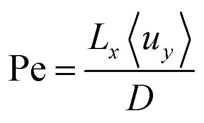 | (1) |
 | (2) |
A key indicator of the flow pattern is the Reynolds number (Re) and is defined in eqn (2). For flow between infinite parallel plates at low Reynolds numbers (Re < 2000), the flow is laminar and a parabolic solution for the velocity profile is found through the solution of the Navier–Stokes equations. Turbulent flow must be avoided as the enhanced mixing perpendicular to the direction of flow contradicts the goal of product separation.
Fig. 1 shows a diagram of the membrane-less photoelectrochemical reactor design. Before the evolved hydrogen and oxygen can mix via diffusion, the dissolved gases are drawn out of the cell via the two electrolyte streams, which will be carrying the respective product.
 | ||
| Fig. 1 Diagram of one unit cell of membrane-less PEC cell. | ||
This design when compared with many other conventional designs in literature relaxes one crucial material constraint. The photo-voltage required to split water is reduced as the ion path length through the electrolyte is minimised leading to low ohmic losses in the solution. Furthermore, the ohmic losses associated with the membrane are removed. The benefits of this membrane-free operation is particularly apparent for alkaline operating conditions where the respective anion exchange membranes suffer from significantly low conductivities and long-term stability issues.10
However, there are inherent challenges associated with this membrane-less design. There is a need for the cathode to be transparent in order for front illumination of an electrode. For back illumination, only the substrate on which the photoabsorber is deposited must be transparent.
This design removes the membrane cost (which may significantly lower capital cost11) but increases operating cost as the fluid must be pumped continuously. There is also a compromise between product cross-over, the pumping cost and device dimensions. Not only would product cross-over lead to lower product collection efficiencies, there would be safety issues as H2 is highly flammable in O2 (LFL = 4 vol%, UFL = 94 vol%, in O2 at 1 atm).
The flow separator (at exit of the cell in Fig. 1) is used to split the fluid flow. For simplicity, this separator is placed on the centreline between the two plates. This may not be the position at which highest product separation occurs as the diffusivities and molar production rates of H2 and O2 differ and an example of optimal separator placement is given in the ESI.†
This work will investigate the design and operational parameters for successful product separation and will not consider the subsequent dissolved gas removal from solution. This step is necessary for a scaled up design and can be achieved in a number of ways, such as through a reduction in pressure (flash), an increase in temperature, or through sparging. Furthermore, if the electrolyte is recycled (which is a practical requirement for large scale operation) dissolved gas removal will become crucial in order to minimise faradaic losses due to the dissolved H2 and O2 remaining in the recycled electrolyte being consumed at the anode and cathode respectively. Future work will investigate the energy efficiency, economics and efficacy of dissolved gas removal methods.
2.2 Laminar flow between two infinite parallel plates
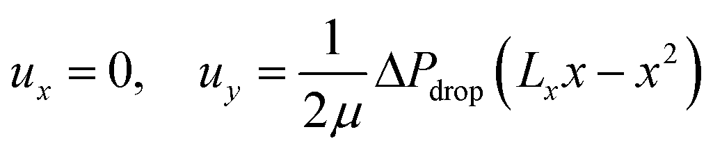
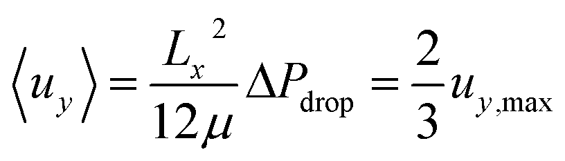
The fluid velocity vector, u can be solved for by combining the incompressible Navier–Stokes equation (eqn (3)), a momentum balance, with the incompressible continuity equation (∇·u = 0), a mass balance. By assuming a laminar flow and negligible gravity effects, there is an analytical solution for the flow profile between two infinite parallel plates separated by distance Lx, which is given by eqn (4). The average velocity is therefore given by eqn (5) and the total flow rate given by eqn (6) where Lz is the depth of the channel.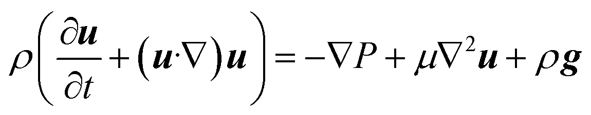 | (3) |
 | (4) |
 | (5) |
![[Q with combining dot above]](https://www.rsc.org/images/entities/i_char_0051_0307.gif) = LzLx〈uy〉 = LzLx〈uy〉 | (6) |
2.3 Mass transport
The continuity equation for the number of moles of species i is given by eqn (7).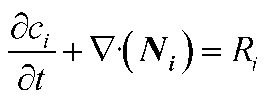 | (7) |
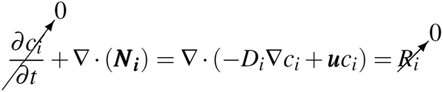
Assuming the transport of dilute species, the flux of the uncharged dissolved gases can be split into the flux due to diffusion and that due to convection (8).
| Ni = −Di∇ci + uci | (8) |
The reaction of H2 and O2 in the bulk fluid can be neglected for the following two reasons: (1) the assumption that the uncatalysed reaction is far slower than the residence time of the reactor.31 (2) By virtue of the design, the product cross-over should be small and hence concentration of both H2 and O2 are never simultaneously high. Therefore eqn (7) & (8) reduces to the following (at steady state).
 | (9) |
If Di is independent of position, the flow is incompressible therefore ∇·u = 0 where u = (ux, uy, uz) and uy is the only non-zero component, then:
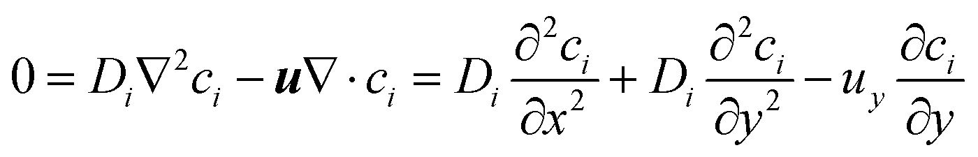 | (10) |
The boundary conditions for species i are given by specifying the concentration at the inlet (ci = ci,0) and 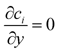 at the outlet. The flux normal to the non-reactive walls is zero (Ni,x = 0). At the electrode that produces species i, the flux is specified as Ni,x = Ri,electrode, where Ri,electrode is the reaction rate at the surface of the electrode. It can be calculated from the current density via Faraday's law (eqn (11)). At the opposite electrode that consumes species i it is assumed that the reaction rate is so fast (due to a large overpotential) that the concentration at the electrode surface is equal to zero (ci = 0).
 | (11) |
2.4 Charge transport in electrolyte
| ∇i = 0, i = −κ∇Φ, ∇2Φ = 0 | (12) |
Neumann boundary conditions apply when the problem is solved for Φ. At the insulating boundary ∇Φ = 0, and at the electrodes ∇Φ = −ielectrode/κ.
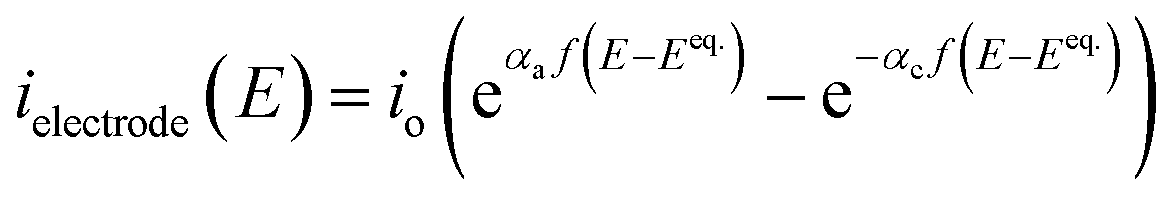
As the electrodes are polarisable and the current density at the electrodes is low enough not to be limited by mass transfer, a secondary current distribution model was employed, and hence a kinetic relationship between the inner potential of the electrode and the current density at the electrode surface is required.
It is important to note that the limiting current density predicted between two flat plates is given by eqn (13) and this theoretical relationship was used to validate the secondary current distribution approximation for all simulations,34 where x is the distance from the start of the flat-plate electrode.
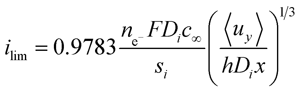 | (13) |
 | (14) |
In comparison, the theory of semiconductor–electrolyte interfaces is far more complex and there is difficulty in creating accurate models from fundamental properties. Approximations derived from the conservation of the charge carriers, such as Gartner's model35,36 neglect space charge layer and surface recombination. The rate of recombination can be included in the model37,38 but these models require fundamental properties and a knowledge of the energetic structure of the semiconductor–electrolyte interface which can be difficult to calculate or measure accurately. The nano-structured surface of the photo-electrodes commonly studied for water splitting complicates this theory further.
Therefore, empirical values of the relationship between the photo-current, the electrode potential and the light irradiance will be used to ensure an accurate representation of photo-electrode kinetics. In order to do this, the incident photon to current efficiency IPCE(λ,E) is calculated by eqn (15) and is measured for different wavelengths of light and electrode potential and in both front and back illumination configurations.
 | (15) |
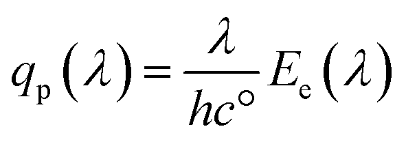
The spectral photon flux qp is related to the spectral irradiance Ee by eqn (16) where h is the Planck constant and c° is the speed of light. The measured IPCE multiplied by the spectral photon flux (calculated from the optical model) can be used to approximate the total photocurrent through integration over all wavelengths, which relies on there being a linear relationship between the total light irradiance (for the same spectrum) and photocurrent.7 The total photo-current then is the summation of the forward and backward components eqn (17).
 | (16) |
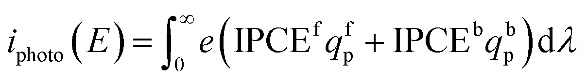 | (17) |
2.5 Optics: transfer matrix method
The design comprises of multiple layers of materials that are modelled using a mixed incoherent and coherent transfer matrix method similar to examples in literature.39–41 A recent review28 discusses the uses and limitations of the transfer matrix method in more detail, but in brief it is used in this work as it can take into account multiple reflections and determine the parasitic absorption losses by the glass, electrolyte and other PEC components. For light incident normal to the layers, the type of polarisation of the light does not affect the transmittance, reflectance and absorptance. In order to reduce the complexity, only equations relating to s-polarisation have been used. In the case of non-normal incident light, the light must be split into both polarisation fractions and solved independently.The electric field intensity is given by the square of the amplitude of the electric field (U = |E|2) and is used for the incoherent transfer matrix formulation, as taking the square of the amplitude removes all phase information (U is not a complex number). As seen in Fig. 2, it can be split into forward and backward propagating waves (U+ and U− respectively) at every position in the multiple layers.
 | ||
| Fig. 2 Diagram of multiple layers showing layer and electric field intensity numbering. | ||
Eqn (18) shows that the incoming and outcoming components of the light at either end of the layers can be related by a simple 2 × 2 matrix called the system transfer matrix. This can be broken down into a matrix multiplication, in the sequence of the layers, of each interface transfer matrix Īk,k+1 (where the subscript denotes the layer before and the layer after the interface) and each layer transfer matrix ![[L with combining macron]](https://www.rsc.org/images/entities/b_i_char_004c_0304.gif) k (where k is the layer). Each of these can be calculated via(20) and (21) where βk = 2πdkñk/λ.
k (where k is the layer). Each of these can be calculated via(20) and (21) where βk = 2πdkñk/λ.
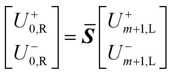 | (18) |
![[S with combining macron]](https://www.rsc.org/images/entities/b_i_char_0053_0304.gif) = Ī0,11Ī1,2…mĪm,m+1 = Ī0,11Ī1,2…mĪm,m+1 | (19) |
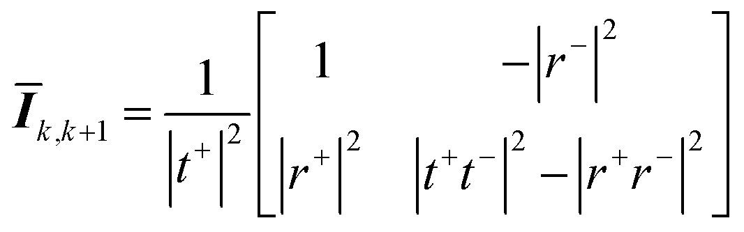 | (20) |
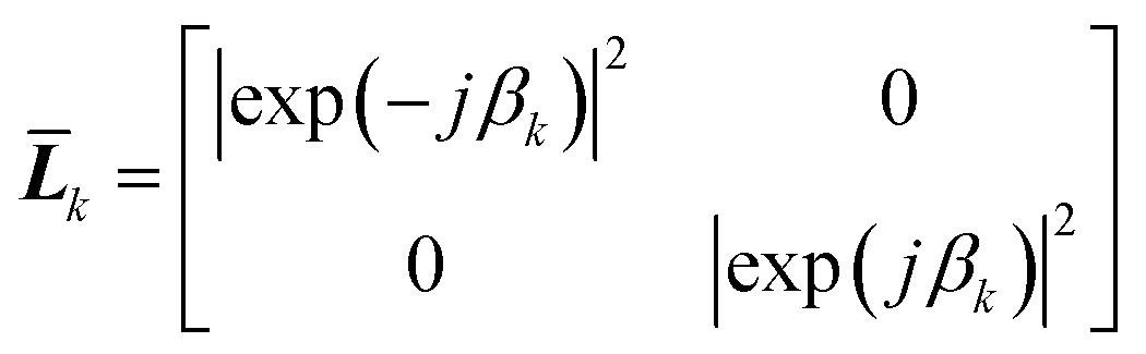 | (21) |
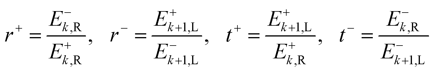
The definitions of the complex transmission and reflection coefficients (t, r resp.) from forward and backward illumination (e.g. t+, t− resp.) are given in eqn (22).
 | (22) |
These can then be calculated using Fresnel's equations for s-polarisation using eqn (23) and (24), where a is the layer from which the light impinges on the interface and b the layer after. Hence for forward travelling light, a = k and b = k + 1 and for backward travelling light, a = k + 1 and b = k.
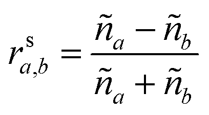 | (23) |
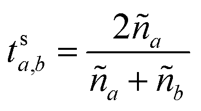 | (24) |
In order to ensure the realistic optical behaviour of the thin film photo-anode and cathode, these layers were considered as a pseudo-interface and an equivalent incoherent interface matrix was calculated from transmittance and reflectance data. This is an approach which is similar to reducing a ‘packet’ of coherent layers to an equivalent interface.39
The equivalent interface is defined by eqn (25) where the intensity transmission and reflection coefficients (not complex) are given by eqn (26) and these can be calculated from measured transmittance and reflectance of the photo-anode layer using eqn (27).
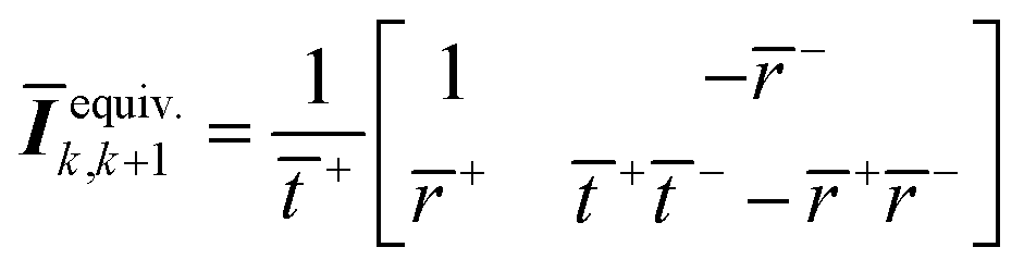 | (25) |
 | (26) |
 | (27) |
The complexity of modelling the multiple layers coherently whilst taking into account the effects from the highly-nanostructured film is beyond the scope of this paper, hence an equivalent interface approach was used. In order to achieve a more accurate optical model, the electromagnetic wave propagation through the nano-structure would have to be calculated by solution of Maxwell's equations.28
The optical power density (Poynting vector) of a plane wave moving forward is given by eqn (28) and a similar one can be written for light moving backwards. This can be used for the incoherent layers as there is no interference.42
 | (28) |
Net power density of light travelling forward is given by eqn (29). From the electric field intensity, the optical power density can be calculated at each point within the layer and the layer absorption can be calculated using eqn (30).
| Pk = P+k − P−k | (29) |
 | (30) |
3 Numerical solution
MATLAB was used to implement a finite difference scheme in order to solve the partial differential equations. The mass-transfer model code's accuracy was verified against a commercial finite element solver (COMSOL). See ESI† for more information on the numerical solution.4 Investigating product cross-over
4.1 Product separation via flow control
Initially, in order to investigate the behaviour of the competing processes controlling cross-over and separation, a simple transport-only model was developed, which specified a constant flux at the surface of the electrode. The electrode current density and rate of reaction can be related by eqn (11) assuming a faradaic efficiency of unity.The competition between the diffusion normal to the electrode surface and convection parallel was found to be the controlling factor in successful product separation. Fig. 3 displays three cases, two of which exhibit cross-over, for different combinations of the relevant dimensionless numbers. These were the mass transfer Péclet number (Pe = Ly〈uy〉/Dx) and the aspect ratio (AR = Ly,electrode/Lx). Fig. 3b displays the concentration contours highlighting the boundary layer. In Fig. 3b the normalised flux against normalised position at the exit of the reactor, shows that the shape of the curves for cases (2) & (3) are very similar. In both these cases the ratio of AR to Pe is constant which is indicative that this may be an important ratio in determining the fundamental behaviour of the cell.
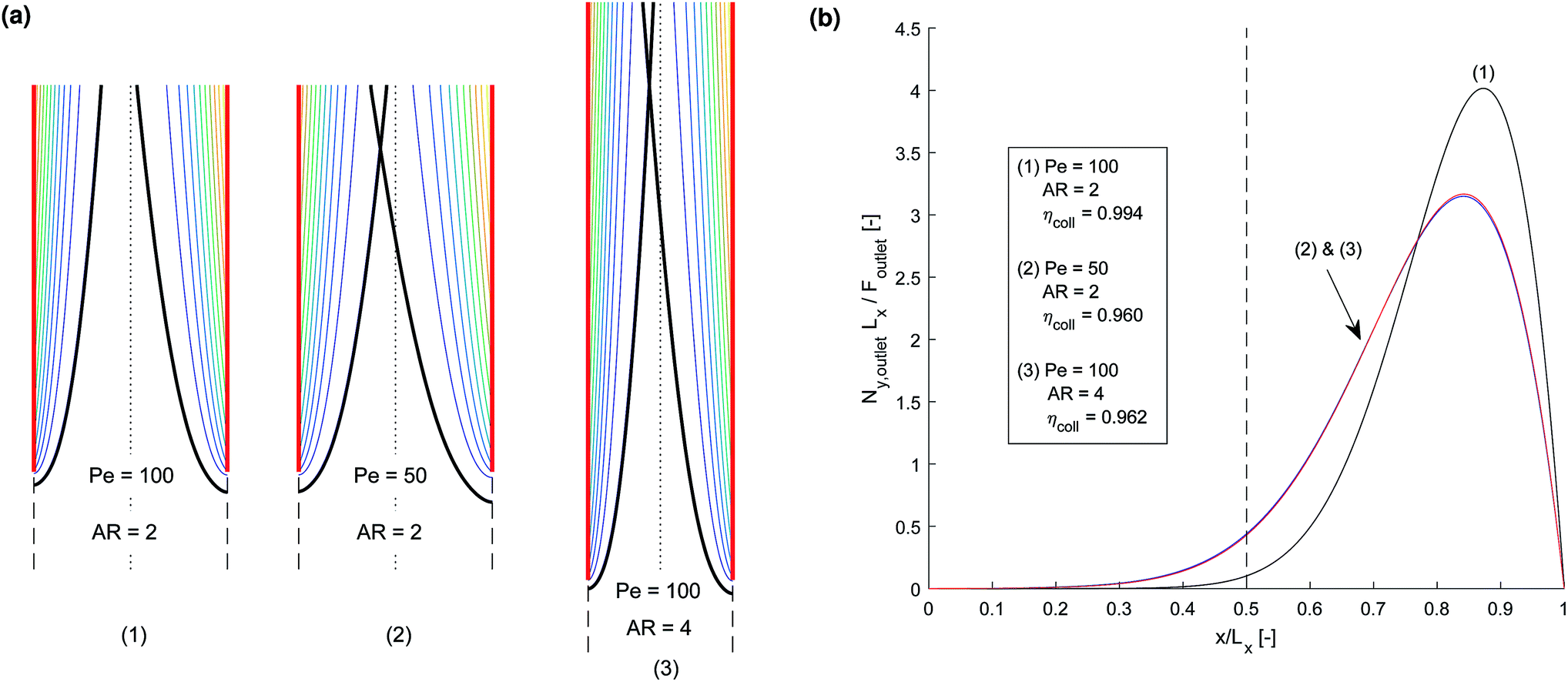 | ||
Fig. 3 Three example channel designs showing small product cross-over for (1) and increased cross-over in (b) and (c) due to insignificantly small Péclet number (Pe) and large aspect ratio (AR) for an arbitrary current density and DH2, DO2 given in Table 1. Note the due to DH2 > DO2, hydrogen is the species that ‘crosses over’ first. (a) Concentration contours where the highlighted contour (black) is where  . (b) Normalised outlet H2 flux against normalised channel width where Foutlet is the total molar flowrate per unit channel depth . (b) Normalised outlet H2 flux against normalised channel width where Foutlet is the total molar flowrate per unit channel depth  . . | ||
As it is crucial to be able to predict the operational regions where product separation is successful, dimensionless analysis is used to investigate this further. In order to do this, a mathematical definition of product cross-over is required and two equally valid definitions are given for completeness.
(1) Collection efficiency is less than some specified amount
 | (31) |
(2) Thickness of the boundary layer crosses centreline
| δ > Lx/2 | (32) |
The boundary layer is defined by eqn (33) as the distance from the surface where the concentration is some arbitrary specified fraction of the concentration at the surface.
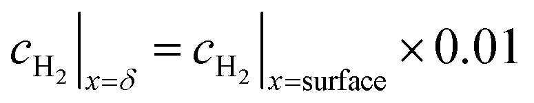 | (33) |
Only the cross-over of hydrogen is considered as the diffusivity of H2 is greater than that of O2 (4.5 × 10⁻⁹ m s−1versus 2.1 × 10⁻⁹ m s−1 respectively)43 meaning H2 will cross-over to the opposite half of the cell first.
4.2 Dimensional analysis for constant electrode flux model
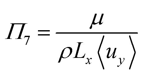
To investigate the conditions under which flow field separation successfully separates the products, Buckingham pi theorem was used44 to cast the model into its dimensionless form. This methodology has the advantage of reducing the problem to a few simple dimensionless numbers, which characterise the behaviour of the system.The dimensionless groups selected, which represent well-known dimensionless numbers, were:
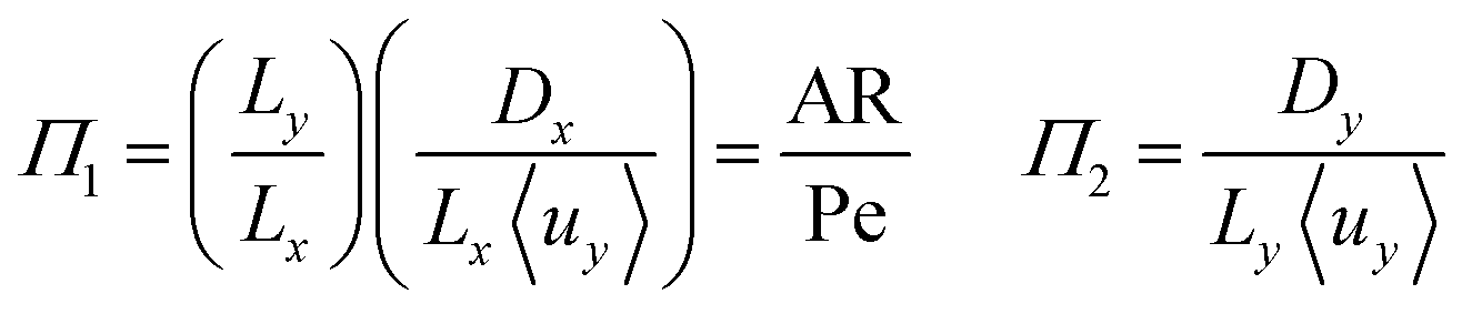
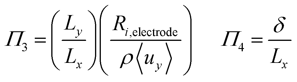

It was found that Π4 was only dependent on Π1 and Π2. By definition, the boundary layer thickness (δ) is the distance at which the concentration is a fraction of the surface concentration, which then means that Π3 does not affect the boundary layer thickness.
For the case of isotropic diffusion (where Dx = Dy), the first and second group can be equated by Π2 = (Lx/Ly)2Π1 → Π2 = AR−2Π1. This means Π2 can be replaced by AR. The parameter space is conveniently investigated by plotting AR/Pe vs. AR as the important regions are displayed in a rectangular plot.
The critical AR/Pe for a given AR, was defined as the point at which product cross-over occurs using the two definitions given in eqn (31) and (33). Fig. 4 displays the critical value of AR/Pe against AR that is required for three values of ηcoll. The critical AR/Pe was to found to tend to a constant for higher aspect ratios. The ability to predict cross-over is important so that when this reactor design is physically built, cross-over can be avoided by choosing to operate at a value smaller than the critical AR/Pe predicted here.
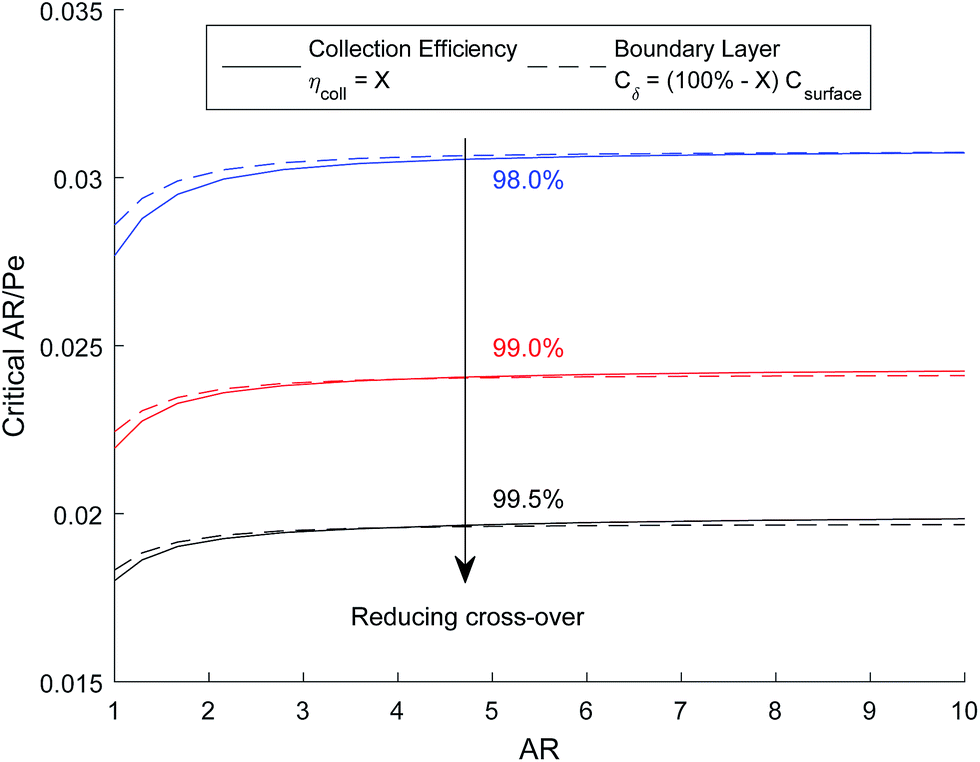 | ||
| Fig. 4 Critical AR/Pe based on collection efficiency and boundary layer definitions. | ||
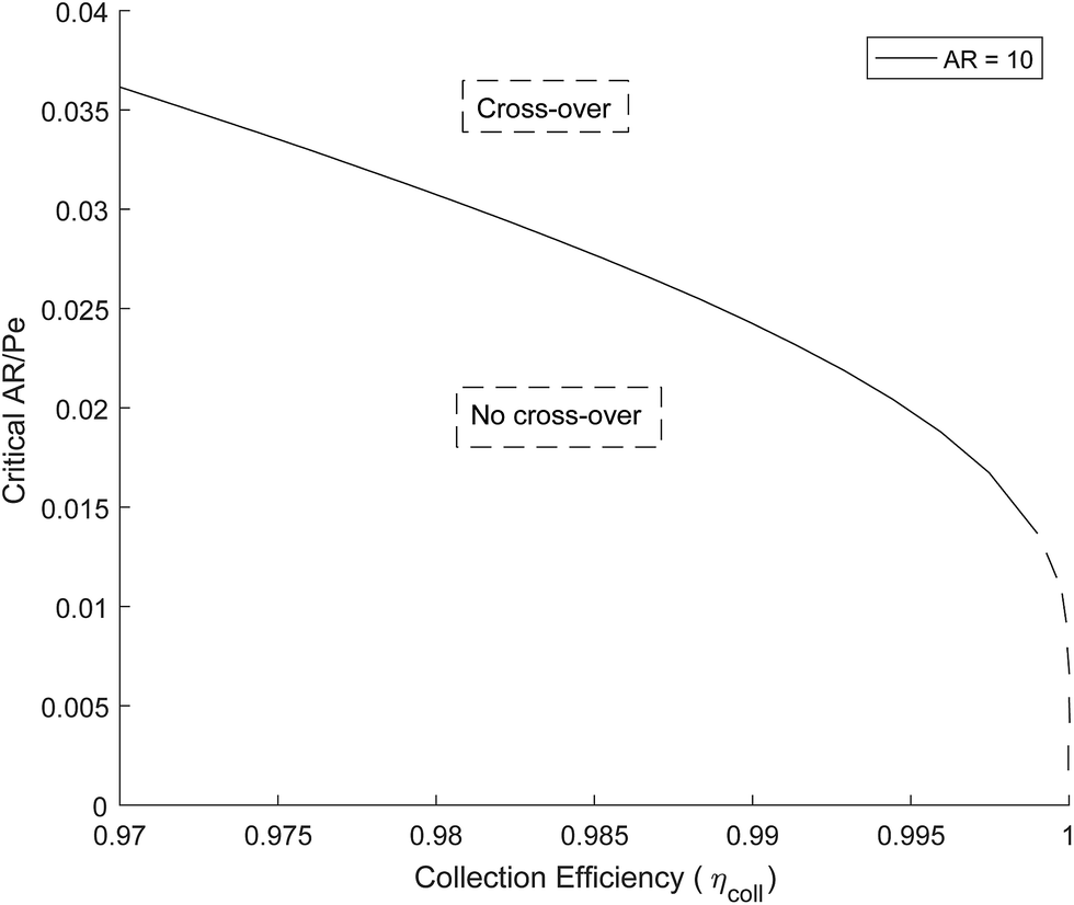
Fig. 5 shows how the critical value of AR/Pe decreases for higher collection efficiencies. This suggests that for a particular gain in collection efficiency, the required operating parameters become exponentially more stringent (when ηcoll → 1, AR/Pe → 0 which could be achieved if 〈uy〉 → ∞ for a fixed AR and Di).
 | ||
| Fig. 5 Critical AR/Pe based on boundary layer definition. | ||
4.3 Bubble formation and process intensification
Laminar flow in the channel will be disrupted if bubbles are allowed to form. The degree of supersaturation of species i (Si) can be calculated using eqn (34) and the equilibrium concentration ci,eq. calculated from Henry's law. Predicting the degree of supersaturation which results before bubble formation occurs is notoriously difficult and hence here, a conservative approach is taken: if S > 1 then bubbles will form. The value for Henry's constant (Hcp) is 7.7 × 10⁻⁶ mol m−3 Pa−1 and 1.3 × 10⁻⁵ for H2 and O2 respectively.45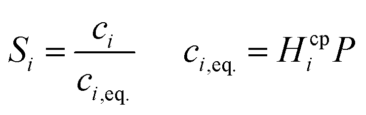 | (34) |
Supersaturation is greatest on the electrode surface nearest the outlet so this value can be used to calculate the limiting surface reaction rate and so limiting current density (viaeqn (11)) at which S < 1 everywhere and so no bubbles should be formed.
Dimensionless analysis again was applied and the effects of various dimensionless numbers on bubble formation investigated. Dissolved hydrogen will reach supersaturation first  hence only the hydrogen supersaturation is used to predict bubble formation. This time the reaction flux at the electrode was non-dimensionalised as
 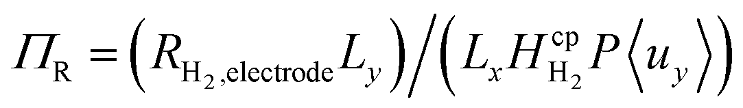 . This term can be understood as the aspect ratio (Ly/Lx) multiplied by the ratio of the surface reaction flux RH2,electrode to the convective removal of saturated solution cH2,eq.〈uy〉, which is similar to the Damköhler number. The aspect ratio (AR) was found to have very little effect on supersaturation when plotted against AR/Pe, although this assumption starts to break down when product cross-over occurs (at the critical AR/Pe and AR given in Fig. 4).
Fig. 6 shows the operational design space, which incorporates both constraints of operation without bubble formation and product cross-over (for a given ηcoll and AR). Therefore, the design of any membrane-less PEC reactor which uses laminar flow to separate products by the methods outlined here, must lie within the operational region in the design space. A power law was fitted (eqn (35)) to represent the relationship between the maximum permissible productivity (ΠR) against AR/Pe.
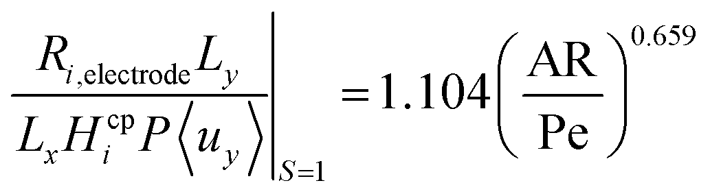 | (35) |
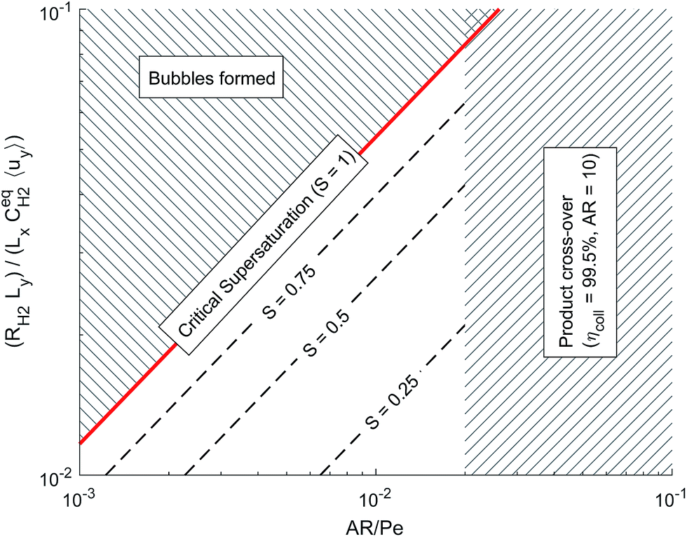 | ||
| Fig. 6 Dimensionless operational design space showing the constraints from bubble formation and product cross-over. | ||
By assuming a faradaic efficiency of unity and that H2 crosses-over and supersaturates first (DH2 > DO2 and 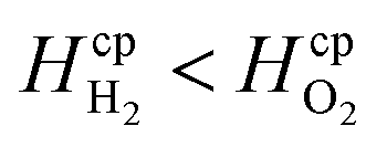 ), eqn (11) and (35) can be rearranged at the point of maximum reaction rate on Fig. 6 (i.e. intercept of critical H2 supersaturation and the product cross over limit where AR/Pe = 0.02 for ηcoll = 99.5% and AR = 10). This gives a relationship between the maximum current and the pressure and channel width (eqn (36)) using DH2 = 4.5 × 10⁻⁹ m2 s−1 and
  .
.
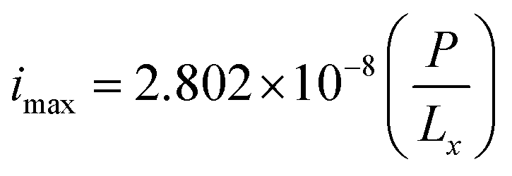 | (36) |
To demonstrate the feasibility of this design, the required pressure for Lx = 0.5 mm for a 10% efficient solar-to-hydrogen process (which equates a current density of approximately 80 A m−2)7 would be 14.3 bar.
From the definition of ΠR and eqn (36), it can seen Ri,electrode ∝ P for a given ΠR value and so doubling the system pressure means the maximum current density before bubble formation can be doubled. Operating at higher pressures would also have the added benefit of reducing the compression work required downstream for hydrogen storage, which in turn may improve the overall energy efficiency of the process.27,46
5 Multi-physics model
5.1 Description of model
The previous section investigated the coupled mass transfer and fluid mechanics of a membrane-less design and the results were shown to be valid (assuming no reaction flux distribution along the electrode) regardless of the optics and type of photo-absorber used. This was subsequently extended into a multi-physics model that incorporates the kinetics and current density distribution within the cell and optical design of the cell and Fig. 7 shows the hierarchy of this. The optical model provides the irradiance on the photo-electrode, which is required for the current density distribution model and this in turn supplies the mass transfer model with the current density distribution on the electrode. | ||
| Fig. 7 Hierarchy of the multi-physics model showing the inputs and outputs of each of the physics. Note that the mass transfer and current distribution models are not coupled, as mass transfer of the ions is neglected (secondary current distribution). Mass transfer of the dissolved products however is not. | ||
The motivation for the developed multi-physics model is the following:
• Validate the conclusions drawn from the constant electrode flux model.
• Study optical parasitic losses.
• Investigate feasible reactor dimensions.
• Introduce the concept of a stacked design incorporating multiple membrane-less cells.
In order to accomplish this, specific electrode and electrolyte properties were selected. For the photo-anode, a thin film of hematite (α-Fe2O3) on a conductive transparent oxide (FTO) was chosen as it is a well-studied material that absorbs in the visible range and is stable in alkaline solution. Furthermore, the assumption of linear dependence of photocurrent with irradiance is valid for hematite (<1 sun),47 which allows the total photocurrent to be predicted accurately by eqn (17). Even though hematite has sub-optimal semiconductor properties and requires a bias in order to split water, it does not hinder the investigation of the reactor design as this is not electrode material specific.
As outlined in detail in the following discussion, the stacked design requires the illumination of the anode through the cathode. Therefore the cathode material must be transparent in order to let light through to the next stack and so platinum nano-particles deposited on FTO was selected. 1 M NaOH electrolyte ensures high conductivity (i.e. low ohmic losses), insignificant pH changes and a high limiting current (see eqn (13)). The optical geometry of one cell can be seen in Fig. 8.
 | ||
| Fig. 8 Optical geometry of one cell. | ||
5.2 Model parameters/experimental details
Table 1 contains all the parameters required for the model. Complete data on both the optical properties and electrochemical performance for the same thin-film of hematite and platinum was not widely available so these were experimentally determined.| Parameter | Symbol | Value/dataset/notes | Units | Reference | |
|---|---|---|---|---|---|
| Spectral irradiance | E e | AM15 – direct + circumsolar | W m−2 nm−1 | 48 | |
| Complex refractive index | Air | ñ | — | — | 49 |
| Glass | ñ | Optiwhite™ | — | 50 | |
| Electrolyte | ñ | Assuming water | — | 51 | |
| Equivalent interface | Pt + FTO | Ī equiv. | See ESI | — | This work |
| Fe2O3 + FTO | Ī equiv. | See ESI | — | This work | |
| IPCE | Front | IPCEf | See ESI | — | This work |
| Back | IPCEb | See ESI | — | This work | |
| Pt exchange current density | i o | 0.411 | A m−2 | This work | |
| Pt cathodic charge transfer coefficient | α c | 0.422 | — | This work | |
| Pt anodic charge transfer coefficient | α a | 0.288 | — | This work | |
| Electrolyte (1 M NaOH) conductivity | κ | 16.26 | S m−1 | 52 | |
| Bias | V bias | 1.4 | V | — | |
| Diffusivity (in water) | H2 | D H2 | 4.5 × 10⁻⁹ | m2 s−1 | 43 |
| O2 | D O2 | 2.1 × 10⁻⁹ | m2 s−1 | 43 | |
| Henry's constant | H2 |

|
7.7 × 10⁻⁶ | mol m−3 Pa−1 | 45 |
| O2 |
|
1.3 × 10⁻⁵ | mol m−3 Pa−1 | 45 | |
| Electrolyte density | ρ | 1040 | kg m−3 | 52 | |
| Electrolyte dynamic viscosity | μ | 1.116 × 10⁻³ | Pa s | 52 | |
Hematite was deposited via spray pyrolysis of an ethanol solution of 50 mol dm−3 FeCl3·6H2O and 0.3 mol dm−3 SnCl2·2H2O onto fluorine doped tin oxide (FTO) glass (Pilkington TEC 8 Ω sq−1). This was then annealed at 500 °C for 1 hour.
Platinum was deposited onto FTO glass (nominal loading 0.1–1 μg cm−2) via dip coating in a solution of platinic acid (1 mol dm−3 H2PtCl6 in 2-propanol) in a procedure similar to Papageorgiou et al.53 The following was repeated twice: (1) the sample dipped in solution and withdrawn at room temperature (2) solvent allowed to evaporate (3) annealed in furnace at 385 °C for 15 min.
The photo-anode performance (in 1 M NaOH) was assessed by calculating IPCE from measurements of photocurrent at various wavelengths of light. The light from the light source (Hamamatsu 75 W ozone-free xenon lamp) passes through a monochromator onto the sample housed in a PTFE cell with quartz windows. Photocurrent was measured with a potentiostat (Autolab PGSTAT 12) at different electrode potentials against an Ag/AgCl reference electrode (Metrohm). The monochromated light intensity was measured using an optical power meter (PM 100, Thorlabs). Fig. 9 shows the front and back illumination IPCE measurements for various electrode potentials.
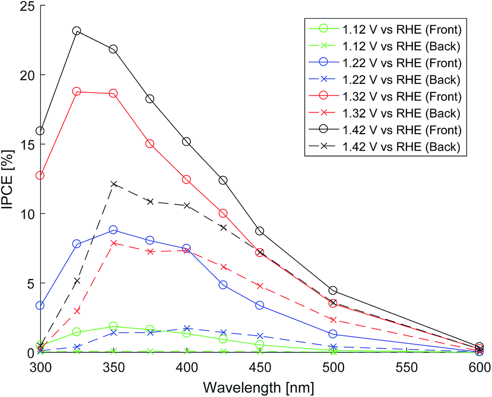 | ||
| Fig. 9 Front and back illuminated IPCE at various electrode potentials. | ||
Performance of the cathode was evaluated through cyclic voltammetry (solartron 1280B) of the Pt deposited on FTO against a Ag/AgCl reference electrode. Butler–Volmer constants were extracted from the curves (CorrView).
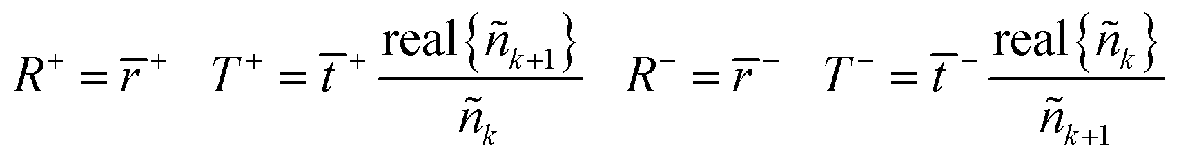
The optical properties of the glass-film–electrolyte interface were measured using a specially designed test cell (see ESI†) and the transmittance and total reflectance was measured using a Shimadzu UV-2600 UV-vis spectrophotometer with an integrating sphere accessory. The intensity matrix for the equivalent interface was then calculated from the test cell's total transmittance and reflectance when irradiated by front and back illumination by the method outlined in the ESI.† The resulting transmittance, reflectance and absorptance of the equivalent layers of the photo-anode and cathode thin films are depicted in Fig. 10.
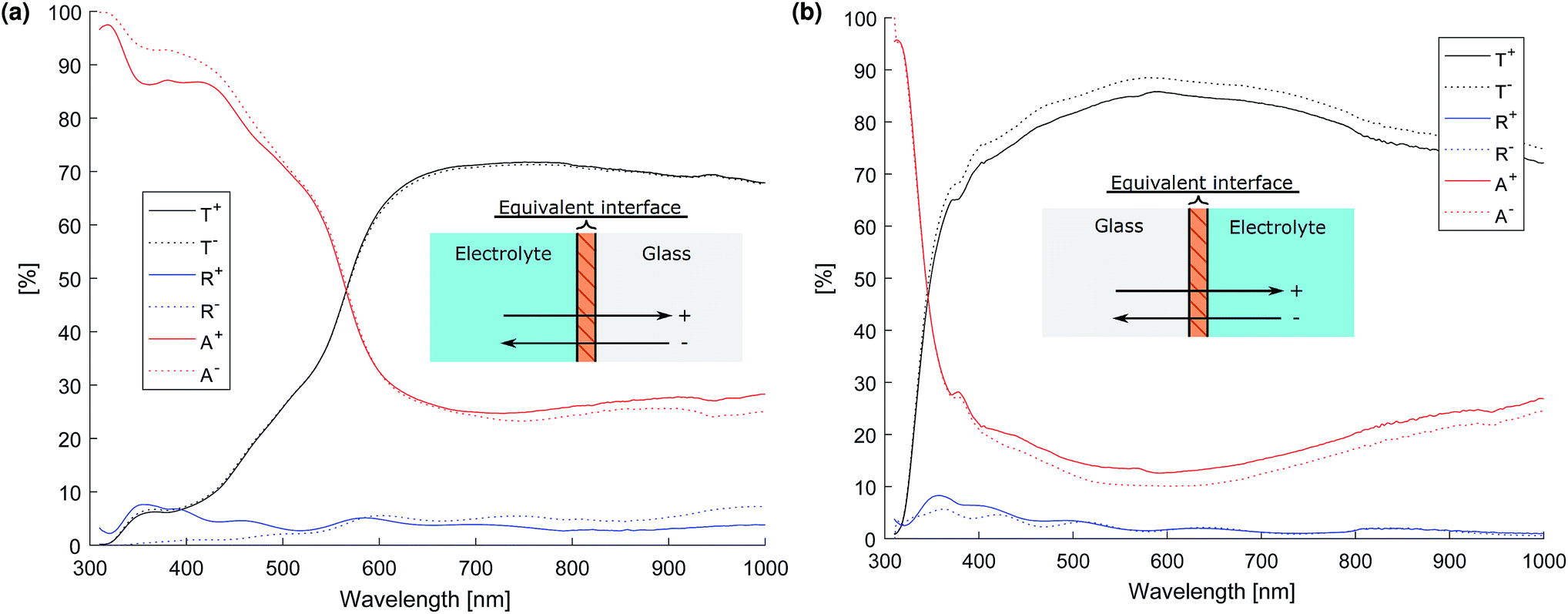 | ||
| Fig. 10 Transmittance, reflectance and absorptance (T, R and A respectively) of the equivalent interface. The superscripts (e.g. R+, R−) denote front and back illumination of the interface as defined by the inset diagram. (a) Photo-anode (Fe2O3 on FTO). (b) Cathode (Pt on FTO). | ||
5.3 Current density distribution
The cathode kinetics are faster than the photo anode leading to a greater current density distribution at the cathode (see ESI†). However, for both electrodes this distribution can be considered insignificant: the maximum current density at the cathode is approximately 0.07% above the mean value at a bias of 1.4 V (Lx = 1 mm, Ly = 10 mm, AR/Pe = 0.015). Therefore the approximation of constant reaction flux at the surface of the electrodes is highly accurate for these example materials and operating conditions. Crucially, this means the results from the previous section, particularly Fig. 6, are validated and that the constant electrode flux model can be used to predict product separation. Hankin et al.14 demonstrated the critical importance of minimising current density distributions in PEC cells, and this design minimises this by virtue of its design.5.4 Optics of single stack
Literature values were used for the complex refractive index of air, glass and the electrolyte (see Table 1) assuming that the complex refractive index of 1 molar NaOH is well approximated by that of water. The thin films of Fe2O3 + FTO and Pt + FTO were modelled as equivalent interfaces using empirical values measured as previously outlined.Fig. 11 shows the normalised layer absorption in order to assess parasitic optical losses for a large channel width Lx = 5 mm so as to demonstrate the absorption by the electrolyte more clearly. At 450 nm, which is near the solar spectrum peak, approximately 75% of the light absorbed is by the photo-anode. Unfortunately the cathode absorbs a significant fraction of light. The total absorbance at 450 nm is approximately 85% meaning that the amount of light that could pass through to the next cell stack is small.
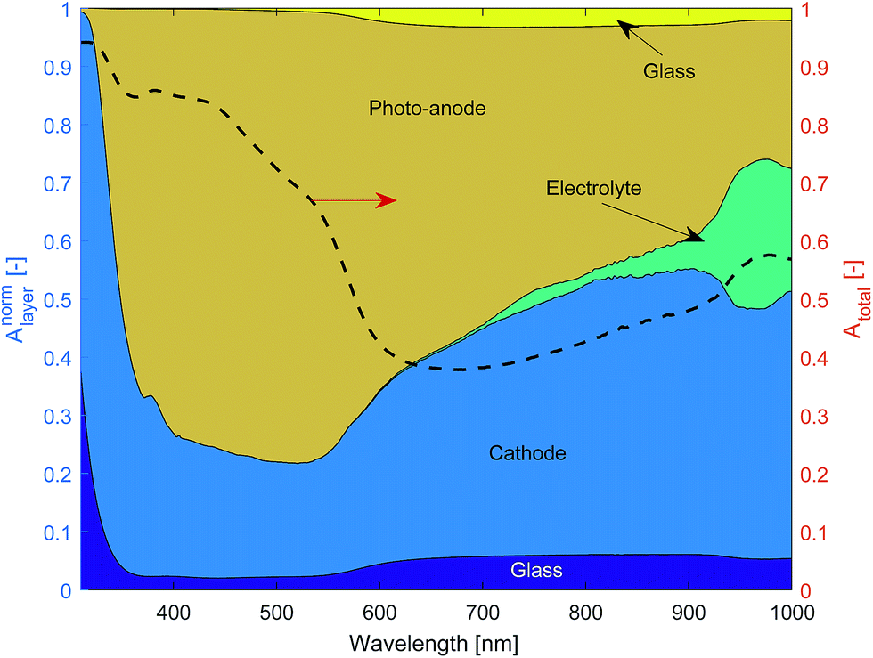 | ||
| Fig. 11 Normalised layer absorption and total absorption of a ‘one cell’ stack (diagram in Fig. 8) for Lx = 5 mm. | ||
The amount of light that is absorbed by the electrolyte in the photo-active region for a 2.3 eV band gap semiconductor such as Fe2O3 (λ < 540 nm) is significantly small. However for a smaller band gap material such as germanium or a significantly larger Lx, the electrolyte absorption can not be neglected. Hence, the findings here are consistent with Döscher et al.54 who showed that the maximum efficiency (from the Shockley–Queisser limit) was reduced once electrolyte absorption was considered, which had design implication especially on the band gaps of multiple junction pv cells.
5.5 Optimization for overall efficiency
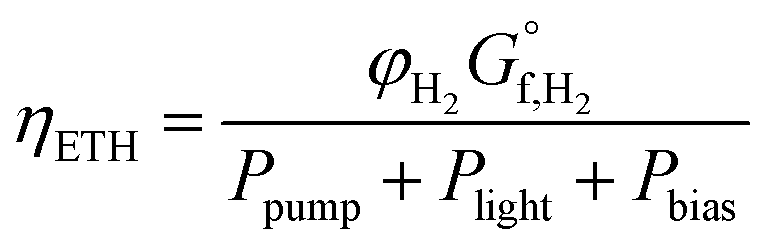
There is now competing phenomena (i.e. cost of pumping, separation of products, optical losses and ohmic solution losses), which means the point of highest overall system efficiency can be found.The definition of solar-to-hydrogen (STH) efficiency can be modified to include the required power of pumping and any bias to create a overall system efficiency or the total input energy to hydrogen efficiency (ETH). This methodology is similar to the “general expression efficiency” outlined by Coridan et al.55
 | (37) |
The pump power required (neglecting gravity) is given by eqn (38) (ref. 56) assuming a reasonable pump efficiency (ηpump ≈ 0.6).
 | (38) |
The sensitivity of the total system efficiency to the channel width (Lx) was quantified with an electrode length of 10 mm and an AR/Pe = 0.015 to ensure product separation. As shown in Fig. 12, this was completed for both the efficiency calculated using the estimated pumping power and a pumping power equal to 100× the estimated. It was expected that smaller channel widths were constrained by pumping power, and for larger channel constrained by the ohmic and optical losses. A linear dependence of ETH against Lx is shown for larger channel widths, which indicates that ohmic losses dominate as optical losses would scale exponentially. This is a consequence of the insignificant parasitic absorption losses below the wavelength 600 nm (see Fig. 11), which is the range in which the anode is photo-active (Fig. 9).
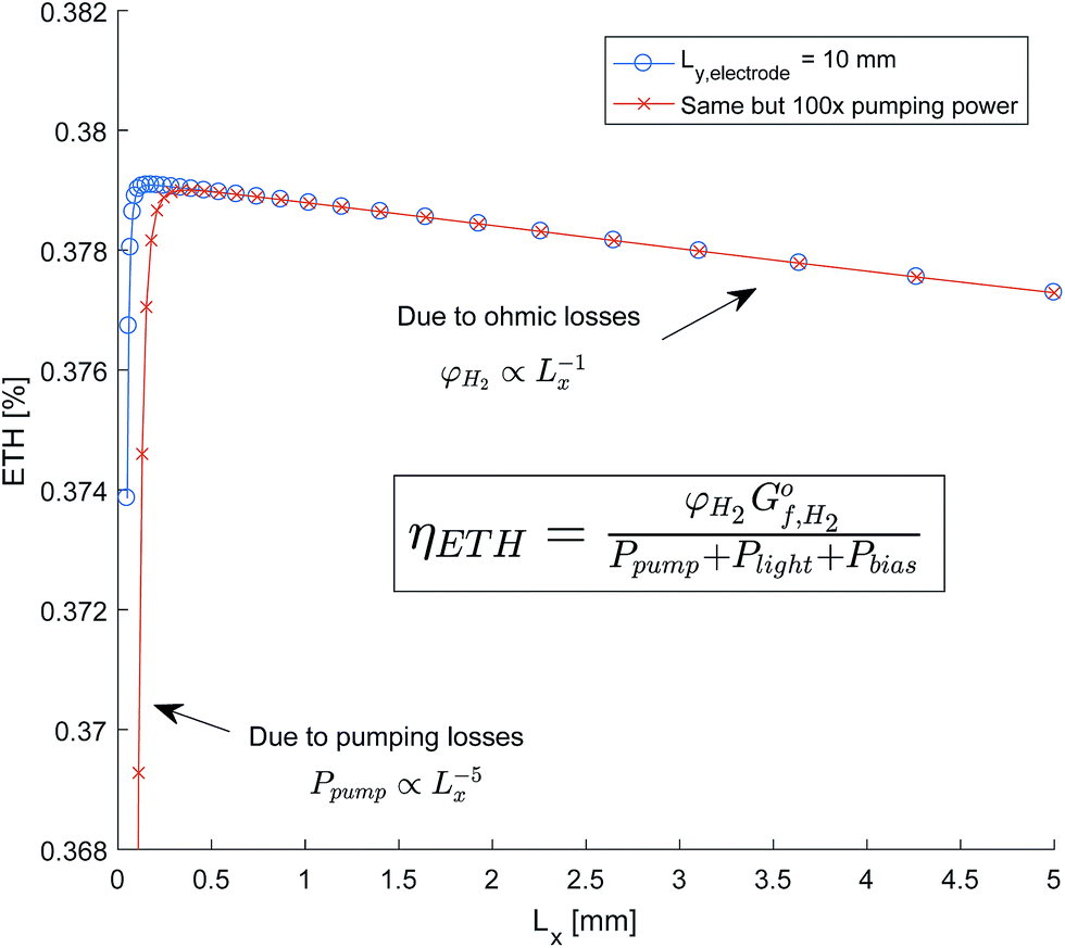 | ||
| Fig. 12 Sensitivity of system efficiency to channel width (Lx). | ||
The resulting design implications is that a larger than optimum channel width can be tolerated without significant reduction in efficiency. This leads to a more feasible dimensions for manufacture as ensuring the accuracy of the channel width to sub-millimetre dimensions may prove challenging.
5.6 Discussion and evaluation of stacked design
If the anode, cathode and substrate materials are all semi-transparent, each cell (Fig. 1) can be stacked in parallel normal to the incoming light (Fig. 13). This means the first cell does not need to absorb all the light in one pass. This is an interesting way to increase the total incident light absorption, which does not rely on nanostructured electrodes that can improve the light absorption of a single thin film.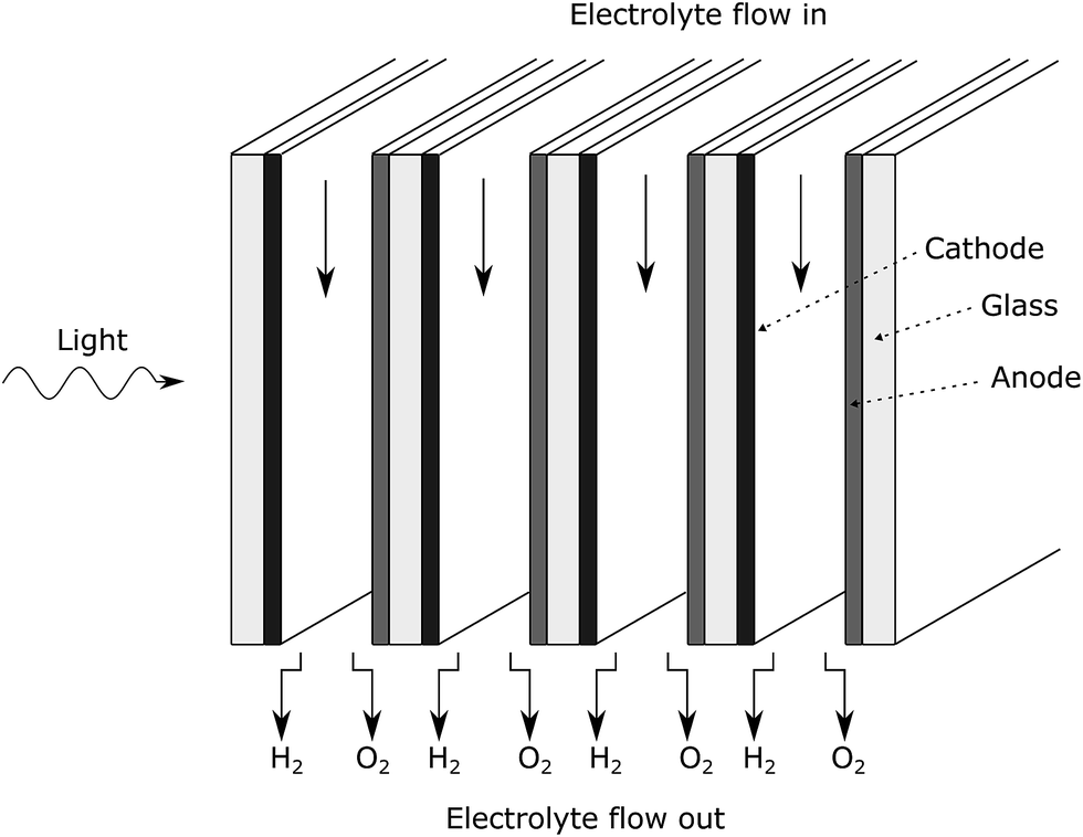 | ||
| Fig. 13 Stacked PEC design. | ||
The stacked design relaxes a typical material constraint that the photo-absorber must have a large absorption coefficient in order to absorb the maximum amount of light in the distance that corresponds to the path length of the exited charges. For materials such as metal oxides with poor carrier mobility, there is then a compromise between the Incident Photon to Current Efficiency (IPCE) and the Absorbed Photon to Current Efficiency (APCE).7 The stacked design means that materials with a high APCE but low IPCE for single pass of light can achieve a high overall IPCE as light is absorbed in multiple passes. An example of such a material is ultra-thin hematite, which has been experimentally shown to achieve impressive APCE and low absorptance (approx. 44% and 20% at 400 nm respectively for 9 nm thick Fe2O3 film with Nb2O5 underlayer on FTO substrate57).
This design lends itself to process intensification and it mimics the stacked designs of electrolysers and fuels cell, which have been successful in making very compact systems. The concentration of light via reflectors and lenses can be offset by stacking more cells together.
The stacked design operating under concentrated sunlight may reduce the cost of pressurising the cell as the incident area to the sun light is reduced. Operating the cell at a high pressure would have the benefits that the produced gases require less energy intensive compression for storage and high pressure would increase the gas solubility, which may suppress bubble formation.
Itoh and Bockris58,59 have previously proposed and investigated a similar stacked configuration. Their simplistic design experimentally demonstrated the improved total photo-current with stacking but however was not a design that could be scaled up due to current density issues and lack of product separation.
The results of efficiency gains through stacking each cell, which allows light to be utilised on multiple passes, are seen in Fig. 14. The efficiency gains are poor due to the low amount of light that is passed through to the next cell for the chosen photo-absorber parameters. For a higher IPCE but lower absorptance photo-absorber such as a thinner layer of hematite on FTO, more impressive efficiency gains are possible.58,59
 | ||
| Fig. 14 Example efficiency gains with multiple cells stacked up showing the individual contribution of each cell to the total energy-to-hydrogen efficiency (ηETH) of the whole stack. | ||
5.7 Example design of stackable reactor
An example of how the reactor design could be constructed can be seen in Fig. 15. It utilises the type of fluid manifold design seen in systems such as flat-plate heat exchangers and fuel cells. As it is being clamped in one direction, this type of design is much simpler to pressurise than other PEC designs. | ||
| Fig. 15 CAD diagram of stacked reactor design. | ||
6 Summary and conclusion
A novel reactor design has been investigated that separates hydrogen and oxygen enriched electrolyte by careful hydrodynamic control of the system alone, which negates the traditional requirement for an ion exchange membrane. This reactor design lends itself to stacking as it permits light to be absorbed in multiple passes, which is a methodology for improving the overall efficiency of high APCE, low absorptance materials such as ultra-thin hematite that have conventionally suffered from low photocurrents as only a fraction of the useful light gets absorbed in the film.Firstly, the mass-transfer of products in the flat plate channel design, assuming negligible reaction flux distribution on the electrode, was explored in order to investigate product cross-over. To ensure the scale-ability of the results and to investigate the fundamental behaviour of the design, a non-dimensional approach was taken. Aspect ratio AR and aspect ratio divided by the Péclet number AR/Pe were found to be the two dimensionless groups on which product cross-over depended. Furthermore, for high aspect ratios, AR/Pe became the key predictor of product cross-over where reducing AR/Pe reduced the cross-over and improved the collection efficiency.
Bubble formation in this design is undesirable as it may disturb the laminar flow through the channel leading to turbulent vortices, which negatively affect product separation. Bubble formation was predicted using supersaturation of the fluid and a relationship between the maximum dimensionless reaction term  and AR/Pe was found. It was hypothesised that in order to ensure bubble-free operation, the reactor could be pressurised with the hydrogen and oxygen removed from solution downstream in a flash vessel.
The performance of an example reactor configuration, based on a hematite (thin film on FTO substrate) photo-anode and a platinum (nano-particles deposited on FTO) cathode, was evaluated using a multi-physics model. This took in to account the optics of the system using a transfer matrix method, and solved the secondary current density distribution, which employed the Butler Volmer equation and integration of IPCE for the cathode and photo-anode kinetics respectively.
The crucial finding of the multi-physics model for this example configuration was to validated the conclusions on predicting the behaviour of the reactor design using the key non-dimensional parameters, where a negligible current density distribution on the electrode was assumed.
The channel width for a given length was optimised using overall system efficiency (which includes the pumping and electrical bias power in the denominator). Due to negligible optical losses in the electrolyte for visible wavelengths, the competing phenomena was the ohmic losses in solution (∝Lx) and the pumping power of fluid (∝Lx−5). It was found that more easily manufacturable channel widths (>1 mm) exhibits an insignificant efficiency loss compared to the optimum.
The overall efficiency increase due to stacking was small due to unfavourable optics of the particular hematite electrode used, which absorbs a large fraction of the light in the first pass. It is expected that with thinner films (i.e. lower absorptance) a greater improvement of overall efficiency could be achieved. This may be a way to improve the optics of high quantum efficiency but low absorptance materials such as ultra-thin hematite.
In this work, it is shown that hydrodynamic control is a feasible method to replace the ion exchange membrane in PEC cells and thereby remove the energy losses and costs associated with it and allow for stacked designs where light is absorbed in multiple passes.
List of symbols
| A j | Absorptance [—] |
| AR | Aspect ratio [—] |
| APCE | Absorbed photon to current efficiency [—] |
| c i | Concentration of species i [mol m−3] |
| c i,eq. | Concentration of species i at equilibrium [mol m−3] |
| c° | Speed of light [m s−1] |
| c ∞ | Concentration of species i infinitely far from electrode surface [mol m−3] |
| d j | Thickness of jth layer of stack [m] |
| D i | Diffusivity of species i [m2 s−1] |
| E | Electrode potential [V] |
| E | Electric field [V m−1] |
| E eq. | Equilibrium electrode potential [V] |
| E e | Spectral irradiance [W m−3] |
| f | =F/RT [V−1] |
| F | Faraday constant [C mol−1] |
| g , g | Gravitational acceleration vector and constant resp. [m s−1] |

| Gibbs free energy of H2 formation [J mol−1] |
| h | Planck constant [m2 kg s−1] |
| H cp i | Henry's constant of species i [mol m−3 Pa−1] |
| i | Current density vector [A m−2] |
| i photo | Photo-electrode current density [A m−2] |
| i electrode | Electrode current density [A m−2] |
| i o | Exchange current density [A m−2] |
| i lim | Mass-transfer limiting current density [A m−2] |
| Ī j,j+1 | Interface matrix [—] |
| IPCEf/b | Incident photon to current efficiency for forward f or backward b illumination [—] |
| j | Imaginary unit  [—] [—] |
|
j
| Layer matrix [—] |
| L x | Channel width (normal to electrode plane) [m] |
| L y | Channel length (direction of flow) [m] |
| L y,electrode | Electrode length [m] |
| L z | Channel depth [m] |
| n e− | Electron stoichiometry in electrode reaction [—] |
| ñ j | Complex refractive index of jth layer of stack [—] |
| N i | Flux of species i [mol m−2 s−1] |
| P | Pressure [Pa] |
| P j | Net optical power density [W m−2] |
| P +/− j | Optical power density of forward (+) and backward (−) travelling light [W m−2] |
| P bias | Bias power [W] |
| ΔPdrop | Pressure drop [Pa] |
| P light | Solar light power [W] |
| P pump | Pumping power [W] |
| Pe | Péclet number [—] |
| q fp | Spectral photon flux (front illumination) [s−1 m−4] |
| q bp | Spectral photon flux (back illumination) [s−1 m−4] |
|
| Volumetric flowrate [m3 s−1] |
r
+/−,![[r with combining macron]](https://www.rsc.org/images/entities/i_char_0072_0304.gif) +/− +/− | Complex reflection coefficients and intensity reflection coefficients from forward and backward travelling light resp. [—] |
| R | Universal gas constant [J mol−1 K−1] |
| R i | Reaction rate of species i [mol m−3 s−1] |
| R i,electrode | Surface reaction rate of species i on electrode [mol m−2 s−1] |
| R +/− | Reflectance from forward and backward travelling light resp. [—] |
| Re | Reynolds number [—] |
| s i | Stoichiometric coefficient of species i in electrode reaction [—] |
|
| System matrix [—] |
| S i | Supersaturation [—] |
| t | Time [s] |
t
+/−, ![[t with combining macron]](https://www.rsc.org/images/entities/i_char_0074_0304.gif) +/− +/− | Complex transmission coefficients and intensity transmission coefficients from forward and backward travelling light resp. [—] |
| T | Temperature [K] |
| T +/− | Transmittance from forward and backward travelling light resp. [—] |
| u | Flow velocity [m s−1] |
| u y | y component of fluid velocity [m s−1] |
| 〈uy〉 | Average (mean) of uy [m s−1] |
| U | Electric field intensity [V2 m−2] |
| U +/− j,L/R | Electric field intensity of forward (+) or backward (−) propagating light on the left (L) or right (R) side of the jth layer of the stack [V2 m−2] |
| α a | Anodic charge transfer coefficient [—] |
| α c | Cathodic charge transfer coefficient [—] |
| β j | =2πdjñj/λ [—] |
| δ | Boundary layer thickness [m] |
| ε 0 | Vacuum permittivity [F m−1] |
| η coll | Collection efficiency [—] |
| η ETH | Total input energy-to-hydrogen efficiency [—] |
| η faradaic | Faradaic efficiency [—] |
| η pump | Pump efficiency [—] |
| κ | Conductivity [S m−1] |
| λ | Wavelength [m] |
| μ | Dynamic viscosity [Pa s] |
| ρ | Density [kg m−3] |
| φ H2 | Molar H2 production rate [mol s−1] |
| Φ | Electric potential [V] |
Acknowledgements
We acknowledge studentship grant for I. Holmes-Gentle from the EPSRC (DTG EP/M506345/1) and for C. A. Mesa from COLCIENCIAS, Colombia. We also acknowledge Anna Hankin and Franky Bedoya-Lora for fruitful discussions on photo-electrochemistry, and José Videira and Tom Wilson for suggesting the application of the Transfer Matrix Method.References
- M. Grätzel, Nature, 2001, 414, 338–344 CrossRef PubMed.
- N. S. Lewis and D. G. Nocera, Proc. Natl. Acad. Sci., 2006, 103, 15729–15735 CrossRef CAS PubMed.
- J. A. Turner, Science, 1999, 285, 687–689 CrossRef CAS PubMed.
- J. Newman, P. G. Hoertz, C. A. Bonino and J. A. Trainham, J. Electrochem. Soc., 2012, 159, A1722–A1729 CrossRef CAS.
- A. Fujishima and K. Honda, Nature, 1972, 238, 37–38 CrossRef CAS PubMed.
- J. W. Ager, M. R. Shaner, K. A. Walczak, I. D. Sharp and S. Ardo, Energy Environ. Sci., 2015, 8, 2811–2824 CAS.
- R. van de Krol and M. Grätzel, Photoelectrochemical Hydrogen Production, Springer, 2012, vol. 102 Search PubMed.
- C. Carver, Z. Ulissi, C. Ong, S. Dennison, G. Kelsall and K. Hellgardt, Int. J. Hydrogen Energy, 2012, 37, 2911–2923 CrossRef CAS.
- M. A. Modestino, S. M. H. Hashemi and S. Haussener, Energy Environ. Sci., 2016, 9, 1533–1551 CAS.
- G. Merle, M. Wessling and K. Nijmeijer, J. Membr. Sci., 2011, 377, 1–35 CrossRef CAS.
- C. A. Rodriguez, M. A. Modestino, D. Psaltis and C. Moser, Energy Environ. Sci., 2014, 7, 3828–3835 CAS.
- Y. Wang, K. S. Chen, J. Mishler, S. C. Cho and X. C. Adroher, Appl. Energy, 2011, 88, 981–1007 CrossRef CAS.
- K. Walczak, Y. Chen, C. Karp, J. W. Beeman, M. Shaner, J. Spurgeon, I. D. Sharp, X. Amashukeli, W. West, J. Jin, N. S. Lewis and C. Xiang, ChemSusChem, 2015, 8, 544–551 CrossRef CAS PubMed.
- A. Hankin, F. E. Bedoya-Lora, C. K. Ong, J. C. Alexander, F. Petter and G. H. Kelsall, Energy Environ. Sci., 2017, 10, 346–360 CAS.
- T. Bosserez, L. Geerts, J. Rongé, F. Ceyssens, S. Haussener, R. Puers and J. A. Martens, J. Phys. Chem. C, 2016, 120, 21242–21247 CAS.
- M. A. Modestino, K. A. Walczak, A. Berger, C. M. Evans, S. Haussener, C. Koval, J. S. Newman, J. W. Ager and R. A. Segalman, Energy Environ. Sci., 2014, 7, 297–301 CAS.
- J. Jin, K. Walczak, M. R. Singh, C. Karp, N. S. Lewis and C. Xiang, Energy Environ. Sci., 2014, 7, 3371–3380 CAS.
- M. Gillespie, F. van der Merwe and R. Kriek, J. Power Sources, 2015, 293, 228–235 CrossRef CAS.
- S. M. H. Hashemi, M. A. Modestino and D. Psaltis, Energy Environ. Sci., 2015, 8, 2003–2009 Search PubMed.
- E. Choban, J. Power Sources, 2004, 128, 54–60 CrossRef CAS.
- W. A. Braff, C. R. Buie and M. Z. Bazant, J. Electrochem. Soc., 2013, 160, A2056–A2063 CrossRef CAS.
- E. Kjeang, B. T. Proctor, A. G. Brolo, D. A. Harrington, N. Djilali and D. Sinton, Electrochim. Acta, 2007, 52, 4942–4946 CrossRef CAS.
- W. A. Braff, M. Z. Bazant and C. R. Buie, Nat. Commun., 2013, 4 DOI:10.1038/ncomms3346.
- E. Kjeang, R. Michel, D. A. Harrington, N. Djilali and D. Sinton, J. Am. Chem. Soc., 2008, 130, 4000–4006 CrossRef CAS PubMed.
- R. S. Jayashree, L. Gancs, E. R. Choban, A. Primak, D. Natarajan, L. J. Markoski and P. J. Kenis, J. Am. Chem. Soc., 2005, 127, 16758–16759 CrossRef CAS PubMed.
- Y. Chen, C. Xiang, S. Hu and N. S. Lewis, J. Electrochem. Soc., 2014, 161, F1101–F1110 CrossRef CAS.
- B. D. James, G. N. Baum, J. Perez, K. N. Baum and O. V. Square, Department of Energy contract GS-10F-009J technical report, Directed Technologies Inc., 2009 Search PubMed.
- E. Kemppainen, J. Halme and P. Lund, J. Phys. Chem. C, 2015, 119, 21747–21766 CAS.
- C. K. Ong, S. Dennison, K. Hellgardt and G. Kelsall, ECS Trans., 2011, 35, 11–19 CAS.
- L. Andrade, T. Lopes, H. A. Ribeiro and A. Mendes, Int. J. Hydrogen Energy, 2011, 36, 175–188 CrossRef CAS.
- A. Berger and J. Newman, J. Electrochem. Soc., 2014, 161, E3328–E3340 CrossRef CAS.
- S. Haussener, C. Xiang, J. M. Spurgeon, S. Ardo, N. S. Lewis and A. Z. Weber, Energy Environ. Sci., 2012, 5, 9922 CAS.
- S. Haussener, S. Hu, C. Xiang, A. Z. Weber and N. S. Lewis, Energy Environ. Sci., 2013, 6, 3605 CAS.
- J. Newman and K. E. Thomas-Alyea, Electrochemical Systems, John Wiley & Sons, 2012 Search PubMed.
- W. W. Gärtner, Phys. Rev., 1959, 116, 84 CrossRef.
- M. A. Butler, J. Appl. Phys., 1977, 48, 1914 CrossRef CAS.
- J. Reichman, Appl. Phys. Lett., 1980, 36, 574 CrossRef CAS.
- H. S. Jarrett, J. Appl. Phys., 1981, 52, 4681–4689 CrossRef CAS.
- E. Centurioni, Appl. Opt., 2005, 44, 7532–7539 CrossRef PubMed.
- C. C. Katsidis and D. I. Siapkas, Appl. Opt., 2002, 41, 3978–3987 CrossRef PubMed.
- S. J. Byrnes, ArXiv e-prints, 2016, arXiv:1603.02720v2.
- S. Jung, K.-Y. Kim, Y.-I. Lee, J.-H. Youn, H.-T. Moon, J. Jang and J. Kim, Jpn. J. Appl. Phys., 2011, 50, 122301 CrossRef.
- E. L. Cussler, Diffusion: Mass Transfer in Fluid Systems, Cambridge University Press, 2009 Search PubMed.
- M. Zlokarnik, Scale-up in Chemical Engineering, JohnWiley & Sons, 2006 Search PubMed.
- R. Sander, Atmos. Chem. Phys., 2015, 15, 4399–4981 CAS.
- B. A. Pinaud, J. D. Benck, L. C. Seitz, A. J. Forman, Z. Chen, T. G. Deutsch, B. D. James, K. N. Baum, G. N. Baum, S. Ardo, H. Wang, E. Miller and T. F. Jaramillo, Energy Environ. Sci., 2013, 6, 1983–2002 CAS.
- F. Le Formal, E. Pastor, S. D. Tilley, C. A. Mesa, S. R. Pendlebury, M. Grätzel and J. R. Durrant, J. Am. Chem. Soc., 2015, 137, 6629–6637 CrossRef CAS PubMed.
- G03 Committee, Tables for Reference Solar Spectral Irradiances: Direct Normal and Hemispherical on 37 Tilted Surface, ASTM International, 2012 Search PubMed.
- P. E. Ciddor, Appl. Opt., 1996, 35, 1566–1573 CrossRef CAS PubMed.
- R. E. Treharne, Ph.D. Thesis, Durham University, 2011.
- G. M. Hale and M. R. Querry, Spie Milestone Series Ms, 1996, vol. 118, pp. 80–88 Search PubMed.
- W. M. Haynes, CRC Handbook of Chemistry and Physics, CRC Press, 95th edn, 2014, p. 2691 Search PubMed.
- N. Papageorgiou, W. F. Maier and M. Grätzel, J. Electrochem. Soc., 1997, 144, 876–884 CrossRef CAS.
- H. Döscher, J. F. Geisz, T. G. Deutsch and J. A. Turner, Energy Environ. Sci., 2014, 7, 2951–2956 Search PubMed.
- R. H. Coridan, A. C. Nielander, S. A. Francis, M. T. McDowell, V. Dix, S. M. Chatman and N. S. Lewis, Energy Environ. Sci., 2015, 8, 2886–2901 CAS.
- R. K. Sinnot, J. M. Coulson and J. F. Richardson, in Chemical Engineering, Chemical Engineering Design, 4th edn, Elsevier Butterworth Heinemann, 2005, Vol. 6 Search PubMed.
- T. Hisatomi, H. Dotan, M. Stefik, K. Sivula, A. Rothschild, M. Grätzel and N. Mathews, Adv. Mater., 2012, 24, 2699–2702 CrossRef CAS PubMed.
- K. Itoh and J. O. Bockris, J. Appl. Phys., 1984, 56, 874–876 CrossRef CAS.
- K. Itoh and J. Bockris, J. Electrochem. Soc., 1984, 131, 1266–1271 CrossRef CAS.
Footnote |
| † Electronic supplementary information (ESI) available. See DOI: 10.1039/c7se00176b |
| This journal is © The Royal Society of Chemistry 2017 |