
 Open Access Article
 This Open Access Article is licensed under a
 Creative Commons Attribution 3.0 Unported Licence
Enhanced ionic conductivity in halloysite nanotube-poly(vinylidene fluoride) electrolytes for solid-state lithium-ion batteries†
Peiqi Lun,
Zilong Chen,
Zhenbao Zhang,
Shaozao Tan and
Dengjie Chen*
and
Dengjie Chen*
Guangdong Engineering & Technology Research Centre of Graphene-like Materials and Products, Department of Chemistry, College of Chemistry and Materials Science, Jinan University, Guangzhou 510632, China. E-mail: dengjie.chen@jnu.edu.cn
First published on 5th October 2018
Abstract
Solid composite electrolytes have gained increased attention, thanks to the improved safety, the prolonged service life, and the effective suppression on the lithium dendrites. However, a low ionic conductivity (<10−5 S cm−1) of solid composite electrolytes at room temperature needs to be greatly enhanced. In this work, we employ natural halloysite nanotubes (HNTs) and poly(vinylidene fluoride) (PVDF) to fabricate composite polymer electrolytes (CPEs). CPE-5 (HNTs 5 wt%) shows an ionic conductivity of ∼3.5 × 10⁻⁴ S cm−1, which is ∼10 times higher than the CPE-0 (without the addition of HNTs) at 30 °C. The greatly increased ionic conductivity is attributed to the negatively-charged outer surface and a high specific surface area of HNTs, which facilitates the migration of Li+ in PVDF. To make a further illustration, a solid-state lithium-ion battery with CPE-5 electrolyte, LiMn2O4 cathode and Li metal anode was fabricated. An initial discharge capacity of ∼71.9 mA h g−1 at 30 °C in 1C is obtained, and after 250 cycles, the capacity of 73.5 mA h g−1 is still maintained. This study suggests that a composite polymer electrolyte with high conductivity can be realized by introducing natural HNTs, and can be potentially applied in solid-state lithium-ion batteries.
1. Introduction
Lithium-ion batteries (LIBs) as almost irreplaceable energy storage devices have been widely applied thanks to their high specific capacity, high stability and low cost.1–4 Other than the wide employment in portable electronic devices, electric vehicles and grid-oriented energy storage applications require increased energy density and stability.1,3,5,6 However, flammable and corrosive organic carbonate liquid electrolytes employed in commercial LIBs encounter lots of issues such as leakage, flammability and poor chemical stability.7–9 Therefore, the application of solid electrolytes instead of liquid electrolytes has gained increased attention, and can potentially solve side effects of liquid electrolytes and improve the safety and service life greatly.10–13 Moreover, the solid electrolyte can effectively suppress lithium dendrites due to the uneven current density and lithium ion distribution during the charge–discharge process, thereby preventing LIBs from the short-circuit.14,15All-solid-state LIBs are considered to be one of the most promising solutions for future advanced LIBs,10,11,16,17 which require solid electrolytes with high ionic conductivity, excellent electrochemical stability, and favorable thermal properties. Among various solid electrolytes, composite polymer electrolytes (CPEs) have shown great potential as alternatives to liquid electrolytes, thanks to the flexibility, as well as the tunability to enhance the ionic conductivity and electrochemical performance.10,11 Various efficient modifications have been employed, such as branching or cross-linking polymers,18 adding active fillers19 and blending plasticizers.20 Meanwhile, lots of polymers have been developed as electrolytes such as polyethylene oxide (PEO),21,22 polyacrylonitrile (PAN),23 polymethyl methacrylate (PMMA)–PEO,24 and PVDF.25 PEO is one of the most extensively investigated substrates, but PEO has several critical issues for practical applications such as the poor film formation ability due to its high viscosity.26 Fluorine-containing polymers such as PVDF have exhibited relatively high electrochemical stability and affinity as electrolytes.27 However, there are still several problems to be solved before the application of PVDF, such as the low ionic conductivity (<10−5 S cm−1) at room temperature. Recently, adding inorganic fillers to PVDF has been widely applied, such as ZrO2,23 SiO2,28 Al2O3,29 etc. An effective filler can reduce the crystallinity of PVDF and increase the segmental motion, thereby boosting the ionic conductivity of PVDF. Very recently, it was reported that the addition of garnet-type active filler (e.g. Li6.75La3Zr1.75Ta0.25O12) could induce the partial dehydrofluorination of PVDF and lead to the enhancement of the ionic conductivity to 5.0 × 10⁻⁴ S cm−1.19 However, it has been recognized that the cubic garnet-type Li7La3Zr2O12 with high ionic conductivity is difficult to prepare, and Li7La3Zr2O12 is sensitive to H2O and CO2.30
Halloysite nanotubes (HNTs, Al2Si2O5(OH)4·nH2O) is an environmentally friendly and low-cost clay material in nature.31,32 HNTs are readily available and abundant in raw materials, so it is suitable for large-scale applications. Thanks to the special 3D nanotube structure, HNTs have been widely applied in various important applications, such as antibacterial coatings,33 transport agents in drug delivery,34 catalyst supports,35 capacitors36 and so on. In this work, CPEs of PVDF–HNTs were prepared via a simple solution casting method. The obtained PVDF–HNTs films exhibit greatly enhanced ionic conductivity, as well as promising thermal stability and mechanical properties. Furthermore, a solid-state lithium battery with the PVDF–HNTs electrolyte, LiMn2O4 cathode and Li metal anode was assembled, exhibiting encouraging electrochemical performance.
2. Experimental
2.1 Preparation of CPEs
All purchased HNTs (Yuanxin Nanotechnology) were pretreated for the further usage. 10 g of HNTs were added in 100 mL of ethanol solution (20 wt%). Then 1 mL of hydrochloric acid (36 wt%) was added for the purification for 24 h. After the centrifugal separation and washing with deionized water to neutral, it was dried at 80 °C for 12 h to remove the residual water. The dried HNTs were further treated in 100 mL of ethanol solution (20 wt%) with 0.1 g of sodium hexametaphosphate (Macklin). After mechanically stirring for 1 h and standing for 24 h, the mixture was centrifuged. Finally, the HNTs were dried in a vacuum oven at 80 °C for 12 h to remove the residuals.To prepare CPEs, PVDF (Shenzhen Tiancheng Technology) and LiClO4 (Aladdin) were firstly dried at 80 °C for 24 h in a vacuum oven to remove the trapped water. After that, PVDF and LiClO4 were dissolved in an appropriate amount of N,N-dimethylformamide (DMF) solvent with a mass ratio of 3![[thin space (1/6-em)]](https://www.rsc.org/images/entities/char_2009.gif) :1. The treated HNTs were also added into the PVDF–LiClO4 solution via controlling the weight percentage of HNTs to 0, 2, 5, 10, and 20 wt% in the total amount of HNTs and PVDF to form CPE-0, CPE-2, CPE-5, CPE-10 and CPE-20, respectively. Then the mixture was stirred at 50 °C for 6 h to obtain a milky mixture for casting. After homogeneously casting onto a glass dish, it was dried in a vacuum oven at 60 °C for 24 h to remove the residual DMF in order to finally form CPEs with the thickness of ∼100 μm.
:1. The treated HNTs were also added into the PVDF–LiClO4 solution via controlling the weight percentage of HNTs to 0, 2, 5, 10, and 20 wt% in the total amount of HNTs and PVDF to form CPE-0, CPE-2, CPE-5, CPE-10 and CPE-20, respectively. Then the mixture was stirred at 50 °C for 6 h to obtain a milky mixture for casting. After homogeneously casting onto a glass dish, it was dried in a vacuum oven at 60 °C for 24 h to remove the residual DMF in order to finally form CPEs with the thickness of ∼100 μm.
2.2 Characterizations
X-ray diffraction (XRD) patterns were obtained by an X-ray diffractometer (Rigaku Smartlab, 3 kW) with Cu-Kα (λ = 1.5406 Å) at 40 kV and 40 mA, collected from 10° to 90° with a step size of 0.02°. Attenuated total reflectance Fourier transforming infrared spectroscopy (FT-IR) was obtained on a Bruker Vertex 70 spectrometer. The morphology and element distribution was recorded using a field emission scanning electron microscope (SEM, Zeiss EVO18) and energy-dispersive X-ray spectroscopy (EDX). The N2 adsorption/desorption isotherms were measured using an Autosorb Quantachrome apparatus (Quantachrome, iQ-MP), and the specific surface area was derived from the Brunauer–Emmett–Teller (BET) method. Thermogravimetry (TG) analysis was performed from room temperature to 600 °C at a heating rate of 10 °C min−1 in the flowing N2 atmosphere on a TG209F3-ASC instrument. The stress and strain curves of CPEs with a size of ∼15 mm × 50 mm × 0.1 mm were recorded by a universal testing machine (UTM-1422).2.3 Electrochemical measurements
Electrochemical performance of CPEs was measured with three configurations. CPEs sandwiched between stainless steel (SS) disks (SS|CPEs|SS) were assembled for the measurement of the ionic conductivity, which could be derived from the obtained electrochemical impedance spectra (EIS). EIS were performed over the frequency of 1 MHz to 0.1 Hz using a Princeton Applied Research (VersaSTAT 4) instrument. To evaluate the electrochemical stability of CPEs, Li|CPEs|SS coin cells (2032) were assembled. The corresponding linear sweep voltammetry (LSV) from 3 V to 8 V vs. Li/Li+ with a scan rate of 10 mV s−1 was carried out. To obtain the lithium-ion transference number, Li|CPEs|Li coin cells (2032) were also assembled. EIS and direct-current (DC) polarization with a DC voltage of 10 mV were recorded.The charge–discharge performance and cycling stability was evaluated on LiMn2O4|CPEs|Li coin cells (2032). To prepare the cathode, Super-P carbon black, PVDF and LiMn2O4 with the mass ratio of 1:2:7 as a conductive agent, a binder, and an active material were mixed with an appropriate amount of N-methyl-2-pyrrolidone (NMP). After mechanically stirring the mixture, a black viscous paste was obtained, which was coated on an aluminum foil and dried at 120 °C in a vacuum oven for 12 h. After drying, a disk-shape electrode with a diameter of 14.0 mm was cut from the aluminum foil. The active material loading in the electrode is ∼1.4 mg cm−2. Then, the LiMn2O4 cathode layer, CPEs and Li foil anode layer were assembled into a battery. To lower the interfacial resistance, dry CPEs of 17.0 mm in diameter were wetted with 5 μL of liquid electrolyte (1.0 M LiPF6 dissolved in ethylene carbonate (EC), ethyl methyl carbonate (EMC), and dimethyl carbonate (DMC) in a volume ratio of 1:1:1). The charge–discharge performance and cycling stability were then measured from 3.4 to 4.5 V using a battery test system (CT2001A, LANHE, China). All preparations were carried out inside a glovebox (Mikrouna, [O2] <0.1 ppm, [H2O] <0.1 ppm) filled with ultrapure Ar (99.999%) when lithium was participated.
3. Results and discussion
3.1 Structure of the CPEs
CPEs of PVDF–HNTs were successfully prepared via a simple solution-casting method. XRD patterns were recorded to analysis the structure evolution after the film-formation, as well as with the addition of lithium salt and HNTs. The corresponding XRD patterns of the HNTs, PVDF, and CPEs are displayed in Fig. 1a. The XRD pattern of HNTs is consistent with the previous literature.37 For the pure PVDF film and CPEs, a slight peak at ∼19.0° corresponds to the α-phase (nonpolar) of PVDF, while a clear and broad peak located at ∼20.3° suggests the formation of the polar β- or γ-phases of PVDF.38 The predominant presence of polar phases in CPEs is beneficial for the ion transportation.39 It is worth noting that the crystallinity of CPEs decreases with the increase of HNTs amount. In addition, the crystallinity could also be obtained from the differential scanning calorimetry (DSC) thermal analysis (Fig. S1†). It could also be observed that the crystallinity of CPEs decreases gradually with the increase of the incorporation of HNTs. A high content of amorphous CPEs will also possibly enhance the ionic conductivity.23,40,41 In addition, it seems that the intensity of the peak at ∼20° of CPE-20 is abnormally enhanced, which is due to the contribution from the HNTs. Increasing the content of HNTs in CPEs leads to the clear appearance of characteristic peaks of HNTs.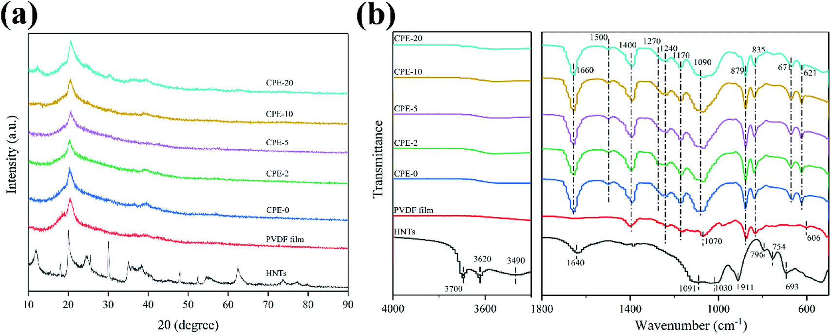 | ||
| Fig. 1 (a) XRD patterns and (b) FT-IR spectra of the HNTs, PVDF film and CPEs. | ||
Fig. 1b shows FT-IR spectra of the HNTs, PVDF film and CPEs. The FT-IR spectrum of HNTs exhibits characteristic peaks at ∼3620 and ∼3700 cm−1, which could be assigned to two Al2OH-stretching bands, where each OH connects to two Al atoms.42,43 A peak at ∼911 cm−1 corresponds to a single Al2OH bending band, confirming the existence of alumina layers.42 A broad peak at ∼3490 cm−1 is due to the SiO–H vibration, indicating the existence of the silica layers.36 In addition, peaks at ∼1091, ∼1030, and ∼796 cm−1 correspond to the Si–O–Si bending vibration, O–Si stretching vibration, and Si–O–Si stretching vibration, respectively.36 Peaks at ∼754 and ∼693 cm−1 are related to the Si–O–Al in-plane bending, reflecting the co-existence of two layers.36 A band at ∼1640 cm−1 is associated to the stretching vibration of OH groups from the absorbed water. For the PVDF film, a weak peak at ∼606 cm−1 appears, suggesting the formation of the α-phase of PVDF, which is also consistent with the XRD result.44 A characteristic peak at ∼1240 cm−1 and ∼1070 cm−1 indicates the existence of the γ-phase of PVDF.44 Peaks at 1170 and1400 cm−1 are the characteristic vibration of CF2.45 After incorporating of HNTs and LiClO4 to form CPEs, not only peaks similar with the PVDF film preserve, but also other characteristic peaks appear or disappear. As expected, peaks due to the addition of LiClO4 at ∼621 cm−1, ∼671 cm−1 and ∼1090 cm−1 are also observed in CPEs,45 but characteristic peaks belong to HNTs can only be observed in CPE-20 due to the poor signal collection at a low content of HNTs. In addition, a newly formed peak at ∼1270 cm−1 implies the formation of the β phase of PVDF, while the peak at ∼606 cm−1 disappears. Bending vibration of OH from the absorbed water appears at ∼1660 cm−1 due to the introduction of LiClO4. It should be noted that the peaks at ∼835 cm−1 and ∼879 cm−1 suggests that the structure of PVDF is still reserved after the incorporation.46 More importantly, the newly detected peak at ∼1500 cm−1 indicates the formation of C![[double bond, length as m-dash]](https://www.rsc.org/images/entities/char_e001.gif) C due to the partial dehydrofluorination.36,47 The detailed assignment of FT-IR is summarized in Table 1. Raman spectra of PVDF and CPEs also confirm the partial dehydrofluorination of PVDF chains (Fig. S2†), where the appearance of additional peaks at ∼1115 and ∼1509 cm−1 of CPEs indicates the formation of CC double bonds.19 As suggested by Nan et al., the partial dehydrofluorination of PVDF could be beneficial for the interaction between components.19
C due to the partial dehydrofluorination.36,47 The detailed assignment of FT-IR is summarized in Table 1. Raman spectra of PVDF and CPEs also confirm the partial dehydrofluorination of PVDF chains (Fig. S2†), where the appearance of additional peaks at ∼1115 and ∼1509 cm−1 of CPEs indicates the formation of CC double bonds.19 As suggested by Nan et al., the partial dehydrofluorination of PVDF could be beneficial for the interaction between components.19
| Vibration modes | Wavenumber (cm−1) | ||
|---|---|---|---|
| HNTs | PVDF film | CPEs | |
| Two Al2OH-stretching bands | 3620, 3700 | ||
| A single Al2OH bending band | 911 | ||
| SiO–H vibration | 3490 | ||
| Si–O–Si bending and stretching vibration | 1091, 796 | ||
| O–Si stretching vibration | 1030 | ||
| Si–O–Al in-plane bending | 754, 693 | ||
| Stretching vibration of OH form water | 1640 | ||
| Stretching vibration of ClO4− | 621 | ||
| Stretching vibration of C–Cl | 671 | ||
| Symmetrical vibration of Li+ and ClO4− | 1090 | ||
| Formation of CC |
1500 | ||
| Bending vibration of OH form water | 1660 | ||
| Characteristic peaks of CF2 | 1170, 1400 | 1170, 1400 | |
3.2 Ionic conductivity of CPEs
EIS measurement was performed at various temperatures to obtain the ionic conductivity and the corresponding activation energy, and the ionic conductivity is calculated according to the eqn (1),
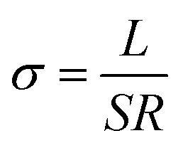 | (1) |
 | (2) |
 | ||
| Fig. 2 (a) EIS plots, (b) ionic conductivity, and (c) Arrhenius plots of CPEs. (d) The absorption–desorption curves and SEM image (inset) of HNTs. (e) A proposed mechanism for the improvement of the ionic conductivity by adding HNTs. | ||
The improvement of the ionic conductivity of CPEs could be mainly attributed to the following aspects. As has been widely recognized, HNTs exhibits a negatively-charged outer surface and positively-charged inner surface.31 This special structure forces the negatively-charged ClO4− to the lumen of HNTs,48 and facilitates the migration of Li+. Moreover, the enhanced ionic conductivity may be resulted from the interaction between HNTs and both ClO4− and PVDF segments, leading to the reduction of the crystallinity of the PVDF and thus providing amorphous regions for fast charge transfer.49,50 In addition, HNTs consist of nanotubes with high specific surface area (see Fig. 2d), which can effectively prevent the recombination of PVDF segments,51 maintaining a high degree of the disorder structure, thus facilitating the transport of Li+. However, the agglomeration of HNTs is readily to occur when increasing the content of HNTs, leading to the phase separation and reducing the probability of the interaction between HNTs and the PVDF segments.23,52 Therefore, CPE-5 exhibits the highest conductivity in this work. A proposed mechanism for the improvement of the ionic conductivity when adding HNTs is shown in Fig. 2e.
3.3 Thermal and mechanical properties
Thermal and mechanical properties are also critically important for the evaluation of CPEs. As shown in Fig. 3a, the thermal decomposition temperature of the pure PVDF film is ∼420 °C. For CPEs, the mass loss starts at ∼300 °C, suggesting the LiClO4 in CPEs interacts with PVDF. This interaction might be beneficial for the ion transfer. Before ∼300 °C, the mass loss is due to the absorbed water since LiClO4 attracts moisture, in accordance with the FT-IR results. In addition, with the increase of the content of HNTs, the mass loss starts at a lower temperature, suggesting the reduced crystallinity with enhanced interaction between HNTs and PVDF. It is worth noting that there is only sharp mass loss step at ∼300 °C for CPE-10 and CPE-20, while two steps are observed for CPE-0, CPE-2, and CPE-5. This observation suggests that the structure evolution dramatically occurs in CPE-10 and CPE-20. More importantly, the stability is undoubtedly affected with the inclusion of the LiClO4 and HNTs, but the thermal decomposition temperature is still much higher than the conventional organic liquid electrolytes, ensuring practical applications. Fig. 3b shows typical stress–strain curves of CPEs. With the addition of HNTs, the elongation of CPEs is greatly improved, yet the tensile strength and Young's modulus are reduced. Notably, CPE-5 shows good mechanical properties, whose elongation is ∼196.8%, tensile strength is ∼23.2 MPa, and Young's modulus is ∼4.3 MPa.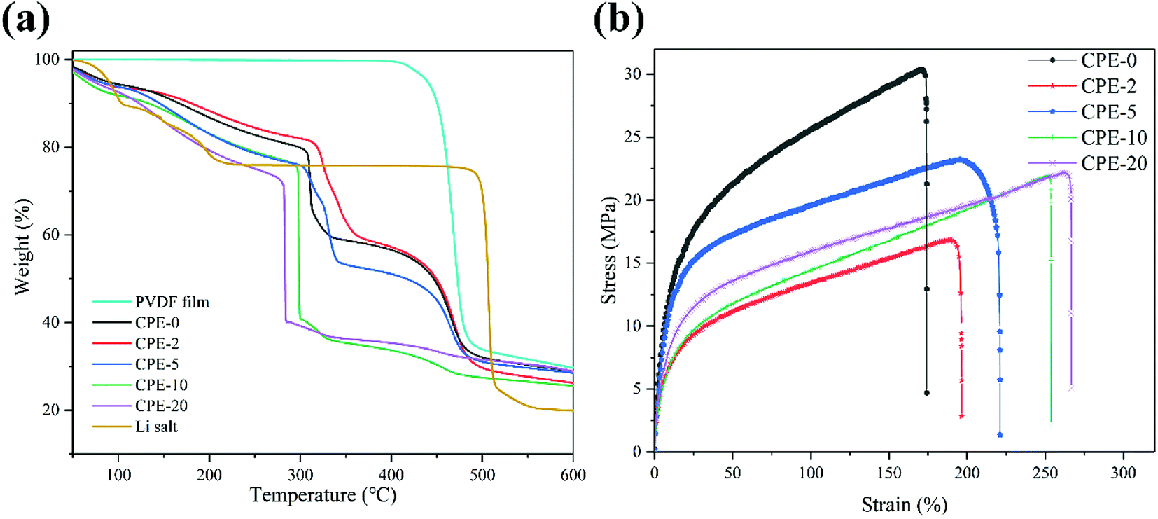 | ||
| Fig. 3 (a) Thermogravimetric analysis of the pure PVDF film, CPEs and LiClO4. (b) Stress–strain curves of CPEs. | ||
3.4 Electrochemical properties of CPEs
Before the measurement of the electrochemical properties of CPEs, SEM images of CPE-0 and CPE-5 are shown in Fig. 4. For CPE-0 and CPE-5, the surface of the film is relatively dense and smooth (Fig. 4a and b), suggesting the uniform distribution of all materials. The thickness of CPE-5 is ∼100 μm, as shown in Fig. 4c.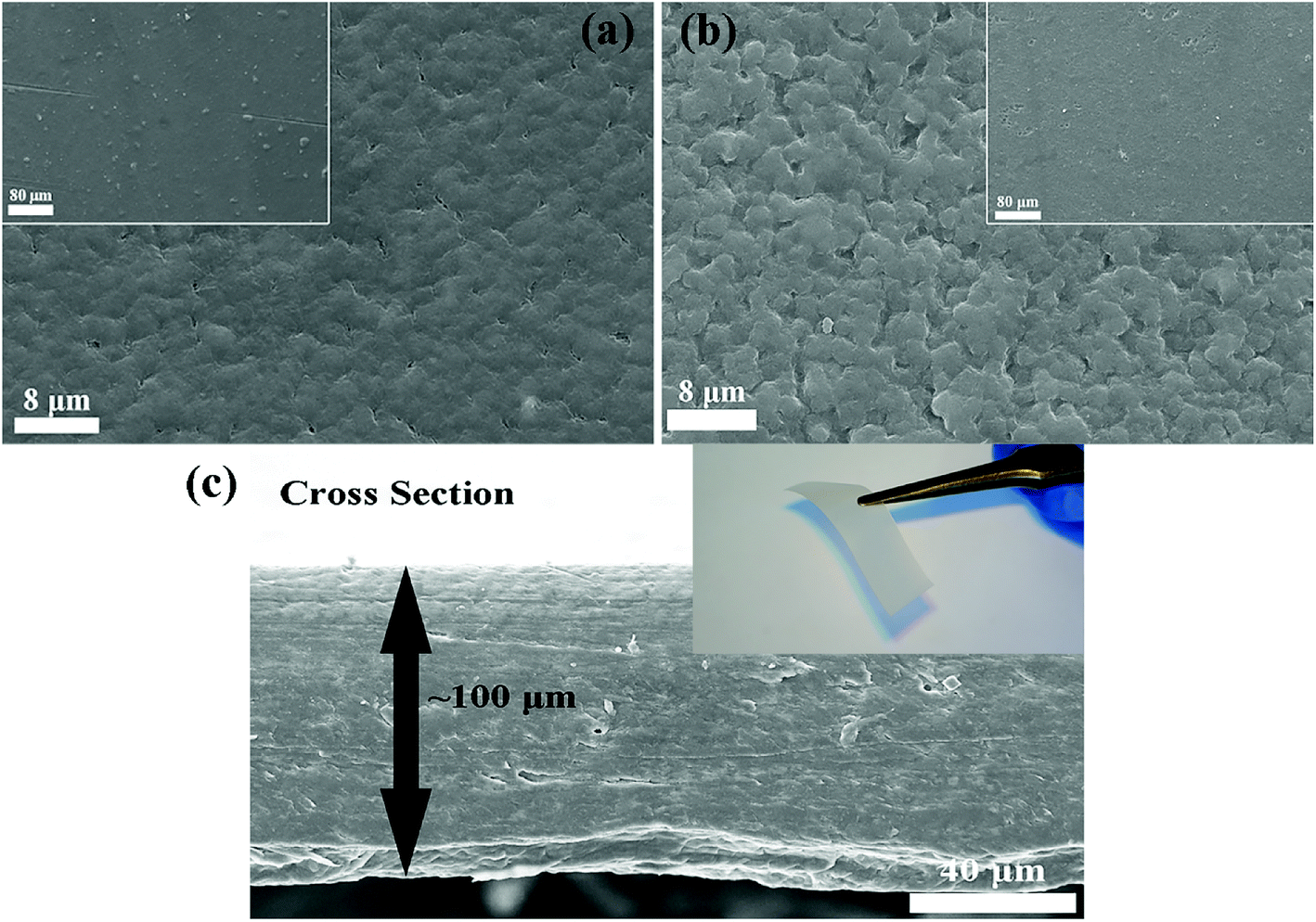 | ||
| Fig. 4 SEM images of (a) CPE-0 and (b and c) CPE-5. | ||
We firstly studied the electrochemical stability window of CPE-0 and CPE-5 by LSV, as shown in Fig. 5a. It can be observed that both CPE-0 and CPE-5 shows a high oxidation potential. CPE-0 shows an oxidation potential of ∼4.63 V vs. Li/Li+, while CPE-5 exhibits an oxidation potential of ∼4.88 V vs. Li/Li+. Besides, the Li+ transference number is of critical importance for the evaluation of CPEs. The Li+ transference number is calculated by eqn (3),
 | (3) |
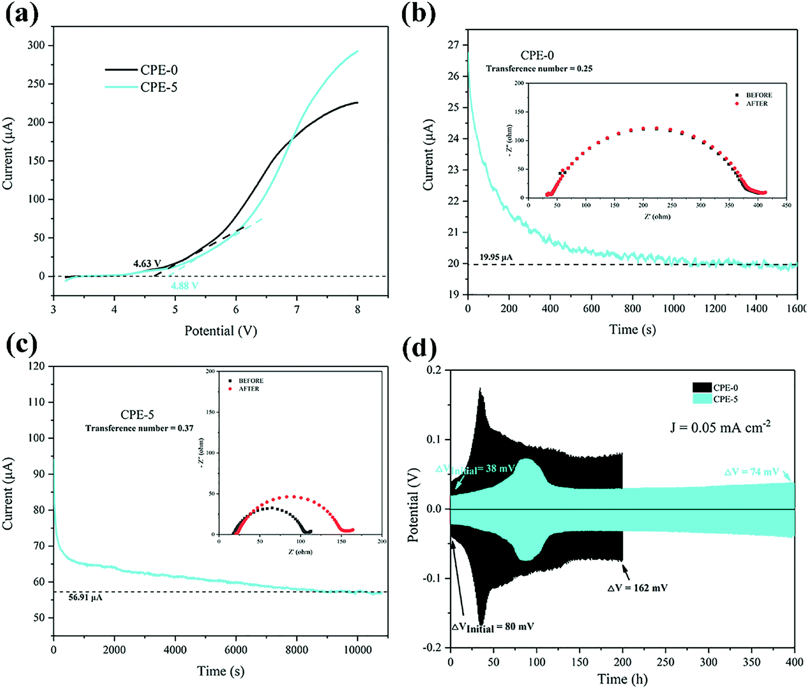 | ||
| Fig. 5 (a) LSV plots of CPE-0 and CPE-5 at a scanning rate of 10 mV s−1. (b and c) Chronoamperometry of the Li|CPEs|Li cells at a potential of 10 mV. EIS spectra of the cells before and after the polarization are shown in the inset. (d) Galvanostatic cycles with a constant current density of 0.05 mA cm−2 for the Li|CPEs|Li cells. | ||
The cell performance using CPE-5 as an electrolyte was further evaluated in a Li|CPE-5|LiMn2O4 cell, as shown in Fig. 6a. The initial discharge capacity is ∼71.9 mA h g−1 at 1C. After 23 cycles the capacity reaches the maximum (∼95.2 mA h g−1 at 1C), and the corresponding coulombic efficiency is ∼102.0%. After 250 cycles, the capacity is ∼73.5 mA h g−1. The initially increased capacity is due to the gradual activation between HNTs and PVDF.22 The increase of the impedance (see Fig. 6b) is attributed to the gradual reaction of CPE-5 with the metal lithium.19 As shown in Fig. 6c, the cell exhibits a good rate capability. Specifically, a relatively stable specific capacity of ∼89.0, ∼87.4, ∼84.8, ∼82.8, and ∼74.4 mA h g−1 is obtained at 0.5, 1, 1.5, 2, and 3.5C. Moreover, Fig. 6d shows that the battery has a low capacity during the activation process, and the 20th discharge platform has relatively high overpotential of ∼0.29 V. The capacity increases after the activation and the overpotential drops to ∼0.24 V.
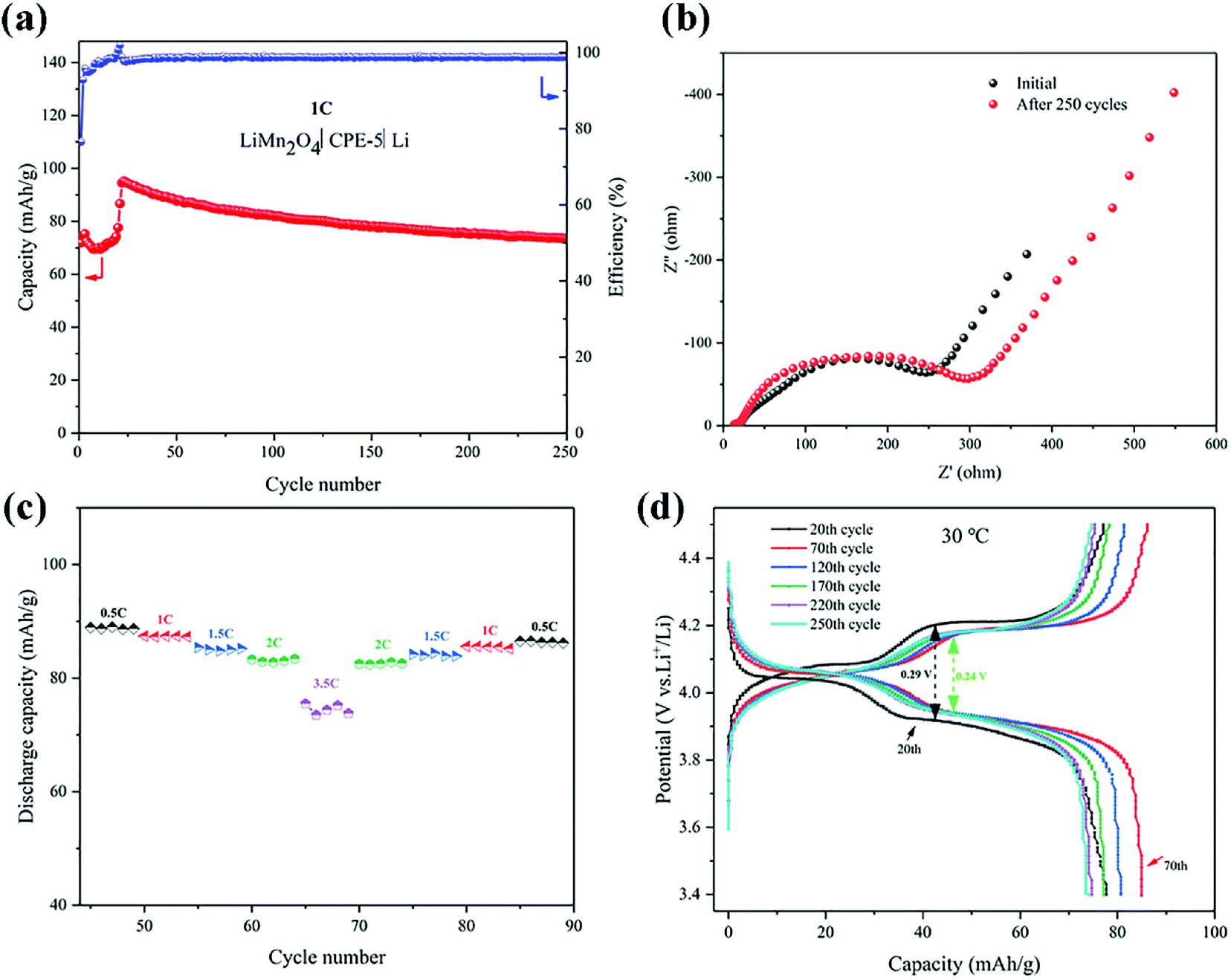 | ||
| Fig. 6 (a) Cycling performance of a Li|CPE-5|LiMn2O4 cell at 1C. (b) EIS spectra before and after 250 cycles. (c) Rate performance of a Li|CPE-5|LiMn2O4 cell. (d) Typical charge–discharge curves of a Li|CPE-5|LiMn2O4 cell. | ||
4. Conclusions
In this work, CPEs containing PVDF as the polymer matrix and HNTs as the filler were prepared via a simple solution casting method. The obtained CPEs show promising thermal and mechanical properties, as well as high conductivity thanks to the special structure. The negatively charged outer surface of HNTs provides a facile channel for Li+ transfer. In addition, the special nanotube structure and the high specific surface area could prevent PVDF segments recombination, leading to the reduction of the crystallinity and the formation of the amorphous zone, thus increasing the ionic conductivity. The interaction between HNTs, lithium salt and PVDF may also contribute to the enhancement of the ionic conductivity. Among CPEs, CPE-5 shows an ionic conductivity of as high as ∼3.5 × 10⁻⁴ S cm−1 with a transference number of 0.37 at 30 °C. The discharge capacity of a LiMn2O4|CPE-5|Li battery reaches ∼71.9 mA h g−1 at 1C in the initial cycle. After 250 charge–discharge cycles, a capacity of ∼73.5 mA h g−1 can be still maintained. This study suggests that a composite polymer electrolyte with high conductivity can be realized by introducing natural HNTs.Conflicts of interest
There are no conflicts to declare.Acknowledgements
This research is supported by the National Natural Science Foundation of China (No. 51702125 & No. 21808080), Pearl River S&T Nova Program of Guangzhou (No. 201806010054), Fundamental Research Funds for the Central Universities (No. 21616301), and the China Postdoctoral Science Foundation (No. 2017M620401).References
- M. Armand and J. M. Tarascon, Nature, 2008, 451, 652 CrossRef CAS PubMed.
- J. W. Choi and D. Aurbach, Nat. Rev. Mater., 2016, 1, 16013 CrossRef CAS.
- M. M. Thackeray, C. Wolverton and E. D. Isaacs, Energy Environ. Sci., 2012, 5, 7854 RSC.
- N. Nitta, F. Wu, J. T. Lee and G. Yushin, Mater. Today, 2015, 18, 252 CrossRef CAS.
- V. Etacheri, R. Marom, R. Elazari, G. Salitra and D. Aurbach, Energy Environ. Sci., 2011, 4, 3243 RSC.
- B. Dunn, H. Kamath and J.-M. Tarascon, Science, 2011, 334, 928 CrossRef CAS PubMed.
- Y. Kato, S. Hori, T. Saito, K. Suzuki, M. Hirayama, A. Mitsui, M. Yonemura, H. Iba and R. Kanno, Nat. Energy, 2016, 1, 16030 CrossRef CAS.
- J. Zhang, J. Zhao, L. Yue, Q. Wang, J. Chai, Z. Liu, X. Zhou, H. Li, Y. Guo and G. Cui, Adv. Energy Mater., 2015, 5, 1501082 CrossRef.
- B. Scrosati, J. Hassoun and Y.-K. Sun, Energy Environ. Sci., 2011, 4, 3287 RSC.
- A. Manthiram, X. Yu and S. Wang, Nat. Rev. Mater., 2017, 2, 16103 CrossRef CAS.
- E. Quartarone and P. Mustarelli, Chem. Soc. Rev., 2011, 40, 2525 RSC.
- J. G. Kim, B. Son, S. Mukherjee, N. Schuppert, A. Bates, O. Kwon, M. J. Choi, H. Y. Chung and S. Park, J. Power Sources, 2015, 282, 299 CrossRef CAS.
- R.-C. Xu, X.-H. Xia, S.-H. Li, S.-Z. Zhang, X.-L. Wang and J.-P. Tu, J. Mater. Chem. A, 2017, 5, 6310 RSC.
- Q. Lu, Y. B. He, Q. Yu, B. Li, Y. V. Kaneti, Y. Yao, F. Kang and Q. H. Yang, Adv. Mater., 2017, 29, 1604460 CrossRef PubMed.
- W. Zhou, S. Wang, Y. Li, S. Xin, A. Manthiram and J. B. Goodenough, J. Am. Chem. Soc., 2016, 138, 9385 CrossRef CAS PubMed.
- R. Bouchet, S. Maria, R. Meziane, A. Aboulaich, L. Lienafa, J.-P. Bonnet, T. N. Phan, D. Bertin, D. Gigmes and D. Devaux, Nat. Mater., 2013, 12, 452 CrossRef CAS PubMed.
- R.-C. Xu, X.-H. Xia, X.-L. Wang, Y. Xia and J.-P. Tu, J. Mater. Chem. A, 2017, 5, 2829 RSC.
- X.-X. Zeng, Y.-X. Yin, N.-W. Li, W.-C. Du, Y.-G. Guo and L.-J. Wan, J. Am. Chem. Soc., 2016, 138, 15825 CrossRef CAS PubMed.
- X. Zhang, T. Liu, S. Zhang, X. Huang, B. Xu, Y. Lin, B. Xu, L. Li, C. W. Nan and Y. Shen, J. Am. Chem. Soc., 2017, 139, 13779 CrossRef CAS PubMed.
- S. Das and A. Ghosh, Electrochim. Acta, 2015, 171, 59 CrossRef CAS.
- X. Tao, Y. Liu, W. Liu, G. Zhou, J. Zhao, D. Lin, C. Zu, O. Sheng, W. Zhang and H.-W. Lee, Nano Lett., 2017, 17, 2967 CrossRef CAS PubMed.
- J. Zhang, N. Zhao, M. Zhang, Y. Li, P. K. Chu, X. Guo, Z. Di, X. Wang and H. Li, Nano Energy, 2016, 28, 447 CrossRef CAS.
- W. Liu, N. Liu, J. Sun, P. C. Hsu, Y. Li, H. W. Lee and Y. Cui, Nano Lett., 2015, 15, 2740 CrossRef CAS PubMed.
- B. Liang, S. Tang, Q. Jiang, C. Chen, X. Chen, S. Li and X. Yan, Electrochim. Acta, 2015, 169, 334 CrossRef CAS.
- J. Yu, S. C. Kwok, Z. Lu, M. B. Effat, Y. Q. Lyu, M. M. Yuen and F. Ciucci, ChemElectroChem, 2018, 5, 2873 CrossRef CAS.
- B. Choi, Y. Kim and H. Shin, Electrochim. Acta, 2000, 45, 1371 CrossRef CAS.
- J. R. Kim, S. W. Choi, S. M. Jo, W. S. Lee and B. C. Kim, Electrochim. Acta, 2004, 50, 69 CrossRef CAS.
- F. Zhang, X. Ma, C. Cao, J. Li and Y. Zhu, J. Power Sources, 2014, 251, 423 CrossRef CAS.
- Z. Zhang, Y. Lai, Z. Zhang, K. Zhang and J. Li, Electrochim. Acta, 2014, 129, 55 CrossRef CAS.
- W. Xia, B. Xu, H. Duan, X. Tang, Y. Guo, H. Kang, H. Li and H. Liu, J. Am. Ceram. Soc., 2017, 100, 2832 CrossRef CAS.
- M. Liu, Z. Jia, D. Jia and C. Zhou, Prog. Polym. Sci., 2014, 39, 1498 CrossRef CAS.
- M. Du, B. Guo and D. Jia, Polym. Int., 2010, 59, 574 CAS.
- D. Fix, D. V. Andreeva, Y. M. Lvov, D. G. Shchukin and H. Möhwald, Adv. Funct. Mater., 2009, 19, 1720 CrossRef CAS.
- M. Liu, Y. Chang, J. Yang, Y. You, R. He, T. Chen and C. Zhou, J. Mater. Chem. B, 2016, 4, 2253 RSC.
- S. Barrientos-Ramírez, G. M. D. Oca-Ramírez, E. V. Ramos-Fernández, A. Sepúlveda-Escribano, M. M. Pastor-Blas and A. González-Montiel, Appl. Catal., A, 2011, 406, 22 CrossRef.
- T. Zhu, C. Qian, W. Zheng, R. Bei, S. Liu, Z. Chi, X. Chen, Y. Zhang and J. Xu, RSC Adv., 2018, 8, 10522 RSC.
- F. Dong, J. Wang, Y. Wang and S. Ren, J. Mater. Chem., 2012, 22, 11093 RSC.
- P. Martins, A. Lopes and S. Lanceros-Mendez, Prog. Polym. Sci., 2014, 39, 683 CrossRef CAS.
- P. Xu, W. Fu, Z. Cui and Y. Ding, Appl. Phys. Lett., 2018, 112, 063904 CrossRef.
- Y. Shen, M. J. Reddy and P. P. Chu, Solid State Ionics, 2004, 175, 747 CrossRef CAS.
- K. Zhu, Y. Liu and J. Liu, RSC Adv., 2014, 4, 42278 RSC.
- J. Zhang, Y. Zhang, Y. Chen, L. Du, B. Zhang, H. Zhang, J. Liu and K. Wang, Ind. Eng. Chem. Res., 2012, 51, 3081 CrossRef CAS.
- J. Liang, B. Dong, S. Ding, C. Li, B. Q. Li, J. Li and G. Yang, J. Mater. Chem. A, 2014, 2, 11299 RSC.
- X. Cai, T. Lei, D. Sun and L. Lin, RSC Adv., 2017, 7, 15382 RSC.
- N. Angulakshmi, S. Thomas, K. Nahm, A. M. Stephan and R. N. Elizabeth, Ionics, 2011, 17, 407 CrossRef CAS.
- F. Liu, M. M. Abed and K. Li, J. Membr. Sci., 2011, 366, 97 CrossRef CAS.
- A. Bottino, G. Capannelli, O. Monticelli and P. Piaggio, J. Membr. Sci., 2000, 166, 23 CrossRef CAS.
- Y. Lin, X. Wang, J. Liu and J. D. Miller, Nano Energy, 2017, 31, 478 CrossRef CAS.
- F. Croce, G. Appetecchi, L. Persi and B. Scrosati, Nature, 1998, 394, 456 CrossRef CAS.
- C. Chiang, Solid State Ionics, 2004, 175, 631 CrossRef CAS.
- S. Chung, Y. Wang, L. Persi, F. Croce, S. Greenbaum, B. Scrosati and E. Plichta, J. Power Sources, 2001, 97, 644 CrossRef.
- G.-M. Hou, M.-Q. Zhang, Y.-F. Huang and W.-H. Ruan, RSC Adv., 2016, 6, 83406 RSC.
- B. Laik, L. Legrand, A. Chausse and R. Messina, Electrochim. Acta, 1998, 44, 773 CrossRef CAS.
Footnote |
| † Electronic supplementary information (ESI) available. See DOI: 10.1039/c8ra06856a |
| This journal is © The Royal Society of Chemistry 2018 |