DOI:
10.1039/C8RA06681G
(Paper)
RSC Adv., 2018,
8, 34241-34251
Synthesis and characterization of TiO2/graphene oxide nanocomposites for photoreduction of heavy metal ions in reverse osmosis concentrate
Received
9th August 2018
, Accepted 22nd September 2018
First published on 5th October 2018
Abstract
In this study, graphene oxide (GO), titanium dioxide (TiO2) and TiO2/GO nanocomposites were synthesized as the catalysts for photoreduction of endocrine disrupting heavy metal ions in reverse osmosis concentrates (ROC). The morphology, structure and chemical composition of these catalysts were characterized by scanning electron microscopy, transmission electron microscopy, powder X-ray diffraction, Brunauer–Emmett–Teller analysis, Barrett–Joyner–Halenda, Fourier transform infrared spectroscopy and Raman spectroscopy. The photocatalytic experiments showed that TiO2/GO nanocomposites exhibit a higher photoreduction performance than pure TiO2 and GO. Under the optimal conditions, the removal rates of Cd2+ and Pb2+ can reach 66.32 and 88.96%, respectively, confirming the effectiveness of photoreduction to reduce the endocrine disrupting heavy metal ions in ROC resulted from the combined adsorption–reduction with TiO2/GO nanocomposites.
1 Introduction
Reverse osmosis (RO) membrane technology is used widely in the treatment of wastewater and potable water, from which the reverse osmosis concentrate (ROC) is produced.1 However, the treatment of ROC is still a challenge.2 The ROC contains high salinity and elevated levels of ions and organics. The organics including endocrine disrupting chemicals (EDCs), emerging contaminants, persistent organic pollutants (PPCPs), pharmaceuticals, etc., can cause significant damages to the environment. Untreated or improperly managed ROC can generate severe ecotoxicological risks and result in adverse environmental effects.3,4
In particular, EDCs consist of a large group of emerging contaminants and are widely distributed in various surface and ground waters, which can disrupt the hormonal system and generate a negative health effect on reproductive, neurological and immune systems.5,6 Generally, EDCs can be classified into five categories: pesticides (atrazine, lindane et al.), persistent organic pollutants (such as DDT and its metabolites), industrial compounds (PCBs, PBBs et al.), chemical substances (phthalates et al.) and heavy metals.7,8 Furthermore, the endocrine systems of organisms and human as well as the reproductive system could be affected by heavy metals. Additionally, cadmium (Cd) as the most toxic heavy metal was found in the ROC. Cd-based compounds are harmful and they can become concentrated in the ecosystem. Similarly, lead (Pb) causes neurological disorders and kidney damage, and can influence the intellectual development of humans.9 Heavy metals would get converted into different forms like Cd2+ and Pb2+ which are highly toxic in comparison to the metal atoms. Even if the concentration of heavy metal ions is not beyond the permissible limit, they could still cause environmental problems.10 Therefore, great attention has been paid to the removal of Cd2+ and Pb2+ from wastewater around the world in recent years. A variety of methods have been used to remove the heavy metal ions such as ion exchange, absorption, membrane filtration, precipitation, photocatalytic reduction, the electrochemical process, etc.11 Among those processes, photocatalytic reduction has been viewed as a safe, simple, efficient, nontoxic and economical method to reduce heavy metal ions.12 In particular, photocatalytic reduction exhibits unique advantages in treatment of low-metal ions-concentration wastewater.
It is well known that TiO2 is a strong and common photocatalyst due to its high photocatalytic efficiency, chemical stability and antibacterial property.13,14 It can absorb light energy to move the electrons up to higher energy levels, generating electron–hole pairs. TiO2 photocatalyst was irradiated by UV light to generate electron–holes which have a high redox ability to degrade pollutants. However, in the practical application, the photocatalytic efficiency of bare TiO2 is low due to a large band gap, the rapid recombination of photogenerated electron–hole pairs, low affinity and poor selection for contaminants.15,16
In order to enhance the photocatalytic ability of TiO2, a variety of approaches was applied to develop TiO2-based composites by designing and modifying TiO2, such as doping with metal or nonmetallic elements, coupling with the semiconductor or incorporating nanostructured carbon materials and so on.14,17,18 In particular, graphene oxide (GO) has drawn much attention as a high potential and efficient material to improve the photocatalytic efficiency of TiO2, since its large specific surface area can facilitate the distribution of TiO2.19,20 In addition, GO can serve as an electronic transfer medium, thus reducing the rate of recombination of electron–hole pairs. The charge transfer rate of electrons will be enhanced due to narrow band gap.21 What's more, the organic pollutants such as EDCs could be absorbed through π–π interactions on the surface of GO.22 Moreover, GO shows a high UV light transparency benefitted from its thin-layered structure which permits UV-light absorption by TiO2.23 Therefore, GO would improve the photocatalytic activity of TiO2 greatly. Similar to GO, rGO showed advantageous enhancement of photocatalytic activity in a number of studies because it can promote charge separation and electron transfer. Due to its outstanding properties, rGO has been investigated as an efficient carbon-based hybrid nanocomposite to improve electronic or photocatalytic performance of materials.24–26 However, the key point is the oxygenous functional groups on the GO surface, such as carboxylic (–COOH), hydroxyl (–OH) and carbonyl (C![[double bond, length as m-dash]](https://www.rsc.org/images/entities/char_e001.gif) O) groups, which played an important role in the absorption. Due to the decrease of oxygenous functional groups, rGO showed a poor adsorption capacity than GO.27,28 Therefore, GO is an ideal substrate to adsorb heavy metal ions because its strong absorption affinity. In general, various studies have already been reported for adsorption of heavy metal ions by GO and GO-based composites. Cui et al. reported the EDTA functionalized magnetic GO for removal of Pb(II), Hg(II) and Cu(II) from wastewater.29 Fang et al. demonstrated GO–NH2 as an adsorbent for the removal of Co(II) ions.30 In our study, TiO2/GO nanocomposites were used to adsorb and reduce heavy metal ions.
O) groups, which played an important role in the absorption. Due to the decrease of oxygenous functional groups, rGO showed a poor adsorption capacity than GO.27,28 Therefore, GO is an ideal substrate to adsorb heavy metal ions because its strong absorption affinity. In general, various studies have already been reported for adsorption of heavy metal ions by GO and GO-based composites. Cui et al. reported the EDTA functionalized magnetic GO for removal of Pb(II), Hg(II) and Cu(II) from wastewater.29 Fang et al. demonstrated GO–NH2 as an adsorbent for the removal of Co(II) ions.30 In our study, TiO2/GO nanocomposites were used to adsorb and reduce heavy metal ions.
TiO2/GO nanocomposites have attracted much attention for degrading pollutants recently. R. Raliya and co-workers reported that TiO2/GO suspension applied for adsorptive and photocatalytic removal of methyl orange.31 H. Yadav et al. prepared TiO2/GO photocatalysts for the degradation of benzene gas, showing a significant degradation compared to pure TiO2 nanoparticles.32 V. Bhatia and co-workers used TiO2/graphene oxide composites as a catalyst for the degradation of atenolol.33
In the present work, GO and TiO2 were synthesized by the modified Hummers method and hydro-thermal method, respectively. Then, TiO2/GO nanocomposites photocatalyst was prepared by hydro-thermal method. Meanwhile, the morphology and structure of GO, TiO2 and TiO2/GO nanocomposites were characterized by scanning electron microscopy (SEM), transmission electron microscopy (TEM), powder X-ray diffraction (XRD), Brunauer–Emmett–Teller (BET), Barrett–Joyner–Halenda (BJH), Fourier transform infrared (FTIR) spectroscopy and Raman spectroscopy. After that, the photocatalytic effects of synthesized TiO2/GO nanocomposites on heavy metal ions reduction were evaluated in batch modes under different conditions. Besides, an optimal experiment condition was obtained to maximize the reduction efficiency of heavy metal ions by TiO2/GO nanocomposites in the photocatalytic reduction reaction. The synthesis route of TiO2/GO nanocomposites and photocatalytic experiments were illustrated in Fig. 1.
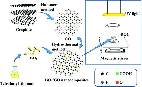 |
| | Fig. 1 The synthesis route of TiO2/GO nanocomposites and photocatalytic experiments. | |
2 Materials and methods
2.1 Synthesis of photocatalysts
2.1.1 Synthesis of GO. The modified Hummers method was used to synthesize GO.34 Firstly, 2.0 g of graphite powder and 2.0 g of NaNO3 with 96 mL of H2SO4 (98 wt%) were mixed in a beaker. Secondly, KMnO4 (12.0 g) was added to the mixture at a slow rate under stirring. Thirdly, the beaker with reactants was placed in an ice bath for 2 h to implement the reaction at 0 °C. Fourthly, the mixture was heated to 55 °C for 1.5 h. Fifthly, 80 mL of deionized (DI) water was added drop wise into the mixture with 30 minutes. Thereafter, H2O2 (15 mL, 30%) was used to react with the excess KMnO4. Remarkably, the color of the mixture was golden at this moment. The mixture solution was diluted with 200 mL of DI water, and the final resulting mixture was centrifuged and washed with DI water several times. The pH value of the mixture was adjusted nearly to 7 by dialysis and the product was dissolved with DI water at a certain proportion (1![[thin space (1/6-em)]](https://www.rsc.org/images/entities/char_2009.gif) :5–1:10). After the ultrasonic treatment, the mixture was dispersed in DI water completely. The supernatant of GO aqueous colloidal suspension was decanted and the centrifuged impurities were discarded. Then, the obtained GO aqueous colloidal suspension was added drop wise into liquid nitrogen and placed in a freeze drier for about 20 h to remove water. The final product is GO. Besides, the concentration of GO aqueous colloidal suspension was about 5 mg mL−1. For comparison, the reduced graphene oxide (rGO) was prepared by thermal treatment at 400 °C in nitrogen atmosphere according to the method described in the ref. 35.
:5–1:10). After the ultrasonic treatment, the mixture was dispersed in DI water completely. The supernatant of GO aqueous colloidal suspension was decanted and the centrifuged impurities were discarded. Then, the obtained GO aqueous colloidal suspension was added drop wise into liquid nitrogen and placed in a freeze drier for about 20 h to remove water. The final product is GO. Besides, the concentration of GO aqueous colloidal suspension was about 5 mg mL−1. For comparison, the reduced graphene oxide (rGO) was prepared by thermal treatment at 400 °C in nitrogen atmosphere according to the method described in the ref. 35.
2.1.2 Synthesis of TiO2. TiO2 was prepared by the hydro-thermal method.15 80 mL anhydrous ethanol and 2 mL C16H36O4Ti was added into a 100 mL beaker. Besides, HF (0.5 mL, 40 wt%) was added drop wise into it. HF greatly controls the formation of the (101) plane of TiO2. The mixture was stirred for about 30 min. Subsequently, the suspension was transferred into a 100 mL Teflon-lined autoclave and heated at 180 °C for 18 h. Then, the mixture was taken out when the autoclave cooled to room temperature naturally. After centrifugation, the product was washed with DI water and anhydrous ethanol several times. Then, the product was dried in a vacuum drying oven at 60 °C for 3 h. Thereafter, the white substance was obtained as TiO2.
2.1.3 Synthesis of TiO2/GO nanocomposites. Hydro-thermal method was used to prepare TiO2/GO nanocomposites. Firstly, 150 mg of TiO2 was dispersed into 150 mL of DI water in a beaker. After that, a certain volume of GO aqueous colloidal suspension was added to the above solution and treated in an ultrasonic bath for 10 min. The volumes of GO aqueous colloidal suspension were 12, 16, 20, 24 and 28 mL, corresponding to 60, 80, 100, 120 and 140 mg of GO, respectively. Finally, the mixture was added dropwise into the liquid nitrogen. Then, the mixture was freeze-dried for 20 h. The product obtained was TiO2/GO nanocomposites with various GO contents. The mass ratios of TiO2 to GO in TiO2/GO nanocomposites were 15:6, 15:8, 15:10, 15:12, 15:14, and the corresponding products were denoted as TiO2/GO-6, TiO2/GO-8, TiO2/GO-10, TiO2/GO-12, TiO2/GO-14, respectively. Moreover, titanium dioxide/reduced graphene oxide (TiO2/rGO) nanocomposites were prepared by thermal treatment at 400 °C in nitrogen atmosphere.
2.2 Characterization
The morphology and structure of GO and TiO2/GO nanocomposites was characterized by SEM (Sirion 200FEI, Netherlands) and TEM (Tecnai F20, 200 kV). The crystalline pattern of samples was investigated by XRD (Cu Kα radiation, Panalytical X PertPro). The BET surface area was determined by N2 adsorption/desorption on an ASAP2020 surface area analyzer using the adsorption date branch in the relative P/P0 pressure range going from 0.0 to 1.0. The pore size distribution of TiO2/GO nanocomposites was obtained by BJH model. In addition, the FTIR (spectral resolution of 0.09 cm−1) spectroscopy was used to determine the functional groups of GO, TiO2/GO and TiO2/rGO nanocomposites from 7800 to 40 cm−1 on a Nicolet 5700 spectrometer (Thermo, Waltham, MA, USA). Raman spectra were obtained using a Horiba Jobin Yvon LABRAM HR Evolution at 785 nm.
2.3 Photocatalytic experiments
ROC was obtained from a petrochemical wastewater treatment plant located in Shandong, China. All the photocatalytic experiments were performed at room temperature in a 500 mL Pyrex breaker. In addition, a high-pressure 500 W Hg lamp was used as the UV light source (maximum energy at 365 nm). First of all, a predetermined amount of photocatalyst was added to wastewater (250 mL). Besides, H2SO4 and NaOH were used to adjust the pH value of wastewater. Before UV irradiation, the wastewater was stirred in the dark for 0.5 h to reach adsorption/desorption equilibrium. Subsequently, irradiation started and samples were collected at a specified interval. Besides, the absorbance of Cd2+ and Pb2+ was determined by a flame atomic absorption spectrophotometer of A3 series with a Beijing Purkinje General instrument (China). And the standard curve method was adopted to determine the heavy metal ions concentration of untreated and treated samples.
3 Results and discussion
3.1 Characterization of photocatalyst
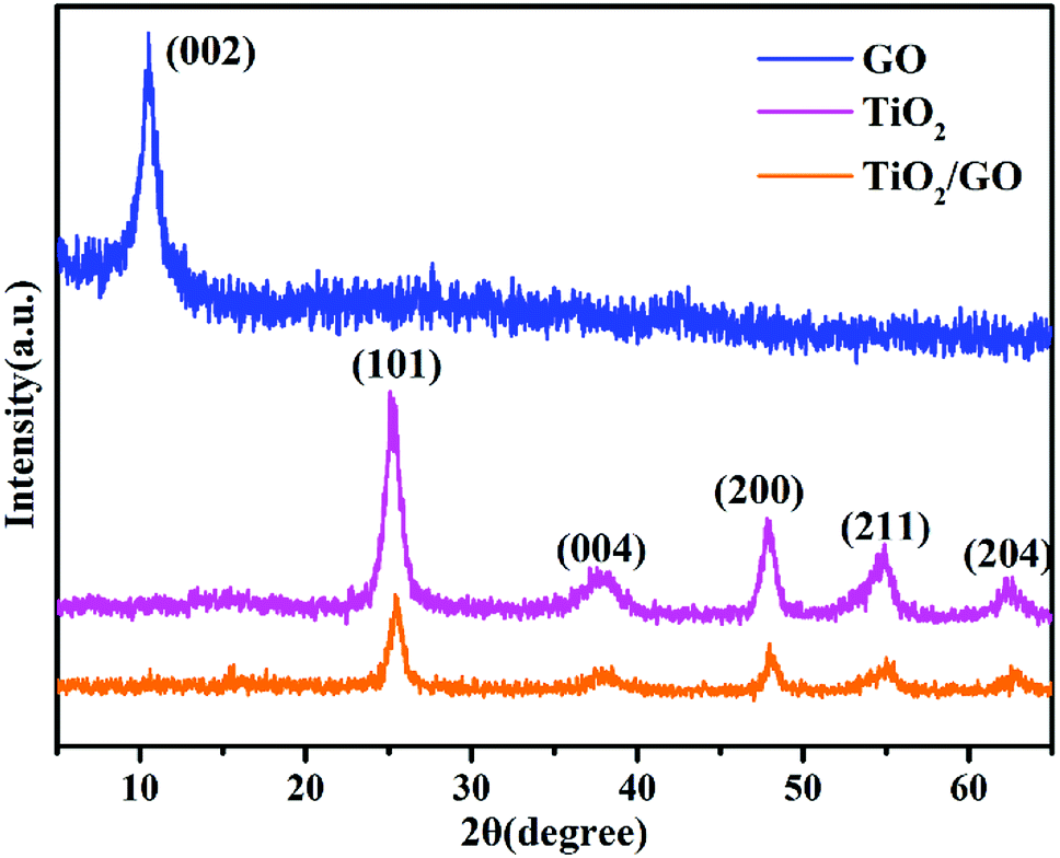
3.1.1 XRD analysis. XRD patterns related to TiO2, GO and TiO2/GO-8 nanocomposites are presented in Fig. 2. It can be seen that the XRD pattern of GO showed a strong peak at 2θ = 10.54° corresponding to the C (002) plane, indicating that the graphite was oxidized to GO successfully.23 Meanwhile, there was no characteristic peak at around 26°, which was confirmed the successful oxidation of graphite into GO. Besides, the interlayer spacing of GO is 0.84 nm, larger than the theoretical value of graphite powder (0.34 nm), probably due to the introduction of oxygen-containing functional groups.36
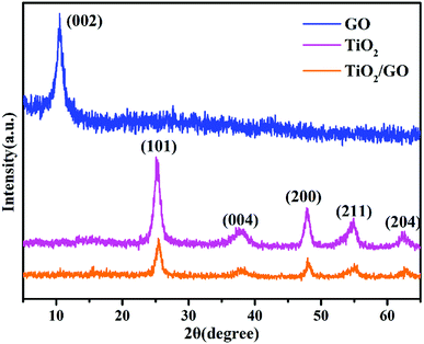 |
| | Fig. 2 XRD patterns of GO, TiO2 and TiO2/GO-8 nanocomposites. | |
From the XRD pattern of TiO2, the characteristic peaks at 2θ values of 25.28°, 37.77°, 47.99°, 54.98° and 62.63° represent the crystal planes of (101), (004), (200), (211) and (204) of anatase TiO2, respectively,37 which are in good agreement with the standard JCPDS Card no. 21-1272. Obviously, peaks of TiO2/GO-8 nanocomposites are similar to TiO2. However, the diffraction peak of GO at 2θ = 10.54° disappeared because the regular stack of GO sheets had been destroyed due to the intercalation of TiO2 nanoparticles.38
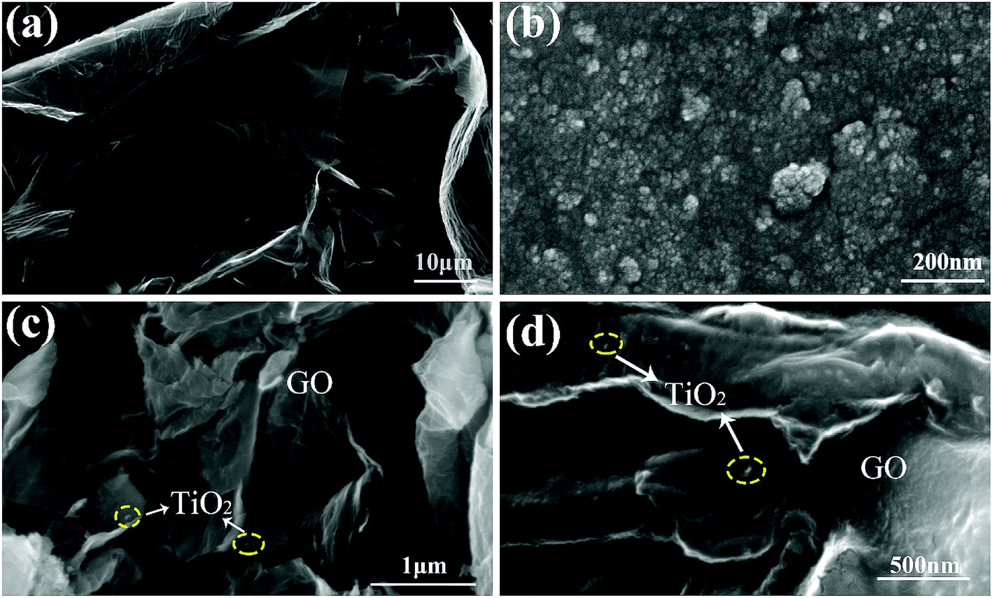
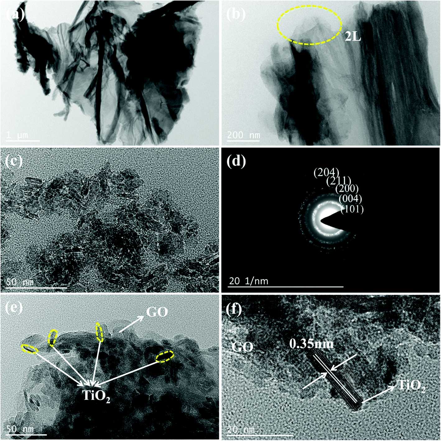
3.1.2 SEM and TEM analysis. The morphology of GO, TiO2 and TiO2/GO-8 nanocomposites was characterized by SEM and TEM. As shows in Fig. 3a, the shape of GO is irregular and GO is a thin-layered structure with wrinkles. The fold structure is formed by stacking. Fig. 4a shows the multi-layer structures due to the introduction of oxidizing functional groups. From the images in Fig. 4a and b, the special layered structure of GO was observed clearly (2 layers), implying that it was helpful to the growth of TiO2.
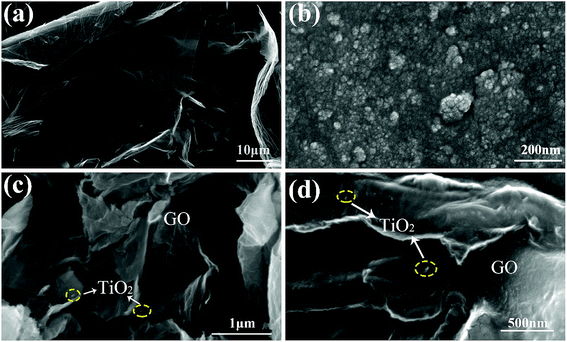 |
| | Fig. 3 SEM images of GO (a), TiO2 (b) and TiO2/GO-8 nanocomposites (c and d). | |
 |
| | Fig. 4 TEM images of GO (a and b), TiO2 with the SAED pattern (c and d), and TiO2/GO-8 nanocomposites (e and f). | |
As shown in Fig. 4c, the morphology and size of the TiO2 nanoparticles are similar. The TiO2 is a rod-like nanoparticle with the average length of about 10 nm and width of about 4 nm. The selected area electron diffraction (SAED) pattern of TiO2 (Fig. 4d) revealed that TiO2 has a polycrystalline structure according to a series of concentric rings with different radii. It has been calculated that the distances between the various diffraction rings and diffraction center are 0.352, 0.237, 0.190, 0.166 and 0.148 nm, respectively, corresponding to the lattice spacings of (101), (004), (200), (211) and (204) planes of anatase TiO2 (JCPDS Card no. 21-1272). Besides, it is consistent with the results of XRD analysis.
Fig. 3c and d shows that the layers of GO curled and the well dispersed TiO2 anchored on the GO planes. This result proved that the TiO2 was successfully loaded onto the GO planes. Most of TiO2 nanoparticles are situated on the edge of GO sheets as shown in Fig. 4e. Fig. 4f shows the lattice fringe is 0.35 nm, which corresponds to the lattice spacing of the (101) plane of anatase TiO2. It is obvious that GO barely affects the morphology and crystalline pattern of TiO2.
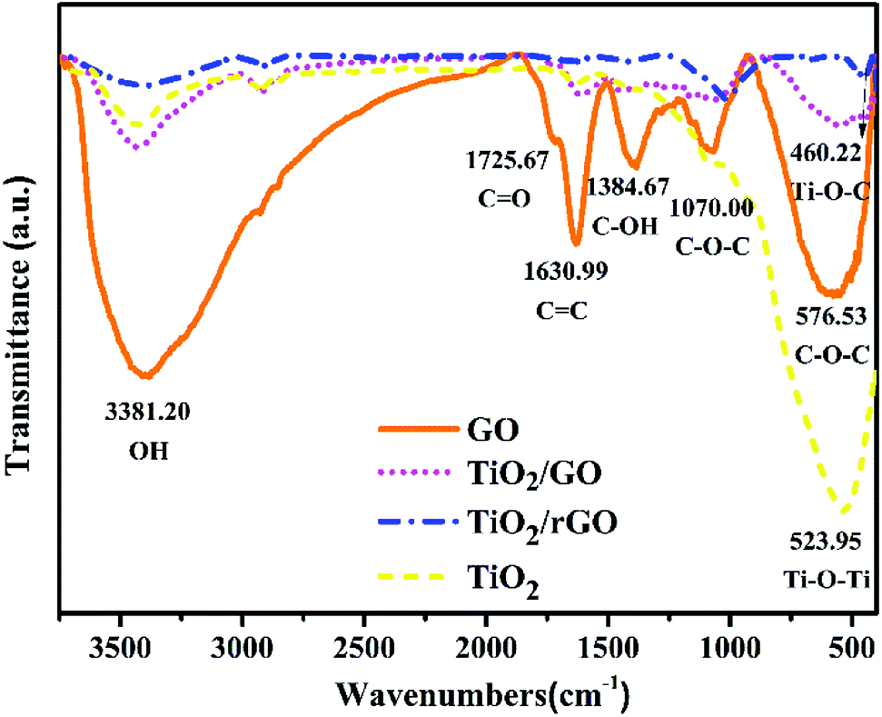
3.1.3 FTIR analysis. Fig. 5 presents the FTIR spectra of GO, TiO2/GO-8 and TiO2/rGO nanocomposites in the wavenumber range of 400–3750 cm−1. The FTIR spectrum of GO indicates that there are a large number of different oxygen-containing functional groups on GO. The strong absorption bands at 576 and 1070 cm−1 correspond to C–O–C stretching vibration. The peak near 1384 cm−1 relates to the carboxyl (C–OH) bending vibration. The presence of an absorption band around 1630 cm−1 is due to CC stretching vibration. Other bands at 1725 and 3381 cm−1 correspond to stretching vibration of oxygen containing functional groups of carboxyl (CO) and hydroxyl (OH), respectively.39 The co-existence of these two stretching vibrations shows the carboxyl (COOH) group on GO. As a result, those polar functional groups can provide anchoring sites for the adsorption of TiO2 on the GO.
 |
| | Fig. 5 FTIR spectra of GO, TiO2, TiO2/GO-8 and TiO2/rGO nanocomposites. | |
By comparison with the GO spectrum, a small amount of oxygen-containing functional groups still exist on the surface of TiO2/GO and TiO2/rGO nanocomposites. For the FTIR spectra of TiO2/GO-8 and TiO2/rGO nanocomposites, the broad band at 460.22 cm−1 was originated from the stretching Ti–O–C.40 Besides, the absorption band near 523 cm−1 corresponded to the Ti–O vibration.41 Furthermore, peak strength of TiO2/rGO nanocomposites is lower than TiO2/GO nanocomposites and some of the peaks even disappear. From the FTIR spectrum of TiO2/rGO nanocomposites, few peaks indicating the oxygen-containing functional groups can be seen after reduction. These oxygen-containing functional groups demonstrate the successful preparation of GO and provide anchoring sites for the adsorption of heavy metal ions on the TiO2/GO-8 nanocomposites. It had been confirmed that the oxygen-containing functional groups played an important role in the adsorption of heavy metal ions.42
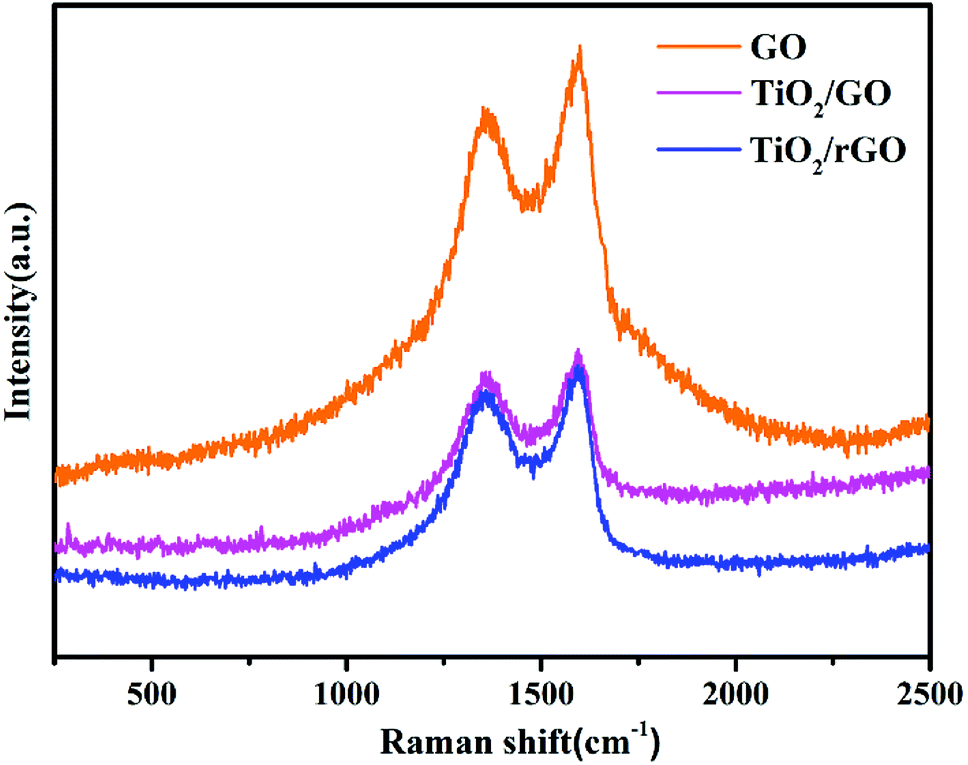
3.1.4 Raman analysis. Fig. 6 shows the Raman spectra of GO, TiO2/GO-8 and TiO2/rGO nanocomposites in the range of 250–2500 cm−1. Raman spectroscopy is used to characterize the structural defects and demonstrate the irregular structure of products. In all samples, there are two bands that can be observed obviously. The first band is the D band for sp3 in plane vibrations of bonded carbon, corresponding to the degree of irregular structure and defect in the graphite layer. Another band is the G band associated with vibrations of sp2 carbon atoms, which is bound with the symmetry and crystallization of carbon.43 In Table 1, the shifting of the D band from 1363 to 1344 cm−1 and the G band from 1600 to 1593 cm−1 showed a red shift for TiO2/GO-8 and TiO2/rGO nanocomposites, due to the introduction of oxygen-containing functional groups into GO during the strong oxidation reaction.44 These functional groups such as hydroxyl and carboxyl were bonded at the GO layer boundaries, resulting in many defects. Moreover, the D and G band values shifted towards the lower values and the D/G intensity ratio (ID/IG) decreasing from 0.927 to 0.908 showed that the GO had been well reduced to rGO.45 The D/G intensity ratio (ID/IG) roughly correlates to the amount of the graphene clusters and defects in the disordered carbon.15 The ID/IG ratios of TiO2/GO-8 and TiO2/rGO nanocomposites are 0.927 and 0.908, respectively, both of which are higher than GO (0.896). This result indicates that loading TiO2 on GO increases the defects. It may be caused by the strong chemical bonding between TiO2 and GO.21,46 Therefore, the ID/IG ratio of TiO2/GO nanocomposites is the highest among all samples, which reveals that more defects exist in TiO2/GO nanocomposites and the graphitization degree of nanocomposites is lower than TiO2/rGO nanocomposites and GO.
 |
| | Fig. 6 Raman spectra of GO, TiO2/GO-8 and TiO2/rGO nanocomposites. | |
Table 1 Comparison of the peak position and intensity of samples
| Samples |
WD (cm−1) |
WG (cm−1) |
ID |
IG |
ID/IG |
| GO |
1363 |
1600 |
925 |
1032 |
0.896 |
| TiO2/GO |
1358 |
1595 |
481 |
519 |
0.927 |
| TiO2/rGO |
1344 |
1593 |
446 |
491 |
0.908 |
3.1.5 N2 adsorption–desorption isotherms and BJH analysis. Fig. 7 shows N2 adsorption–desorption isotherms and BJH pore size distribution of TiO2/GO-8 nanocomposites. The N2 adsorption–desorption isotherms of the as-prepared TiO2/GO-8 nanocomposites exhibit type IV characteristics, which is one of the main characteristics of mesoporous materials. It is further demonstrating the existence of a large number of mesopores. Major pore size distribution of TiO2/GO-8 nanocomposites is ranged from 2 to 7 nm with a peak around 5.24 nm, which is well-defined mesoporous structure, as shown in the inset of Fig. 7. The surface area of TiO2/GO-8 nanocomposites is calculated to be 128.41 m2 g−1 based on the BET model, which is greatly larger than that of pure TiO2 (59.51 m2 g−1). The large BET surface area and mesoporous structure enhance the photogenerated electrons and holes to participate in photocatalytic activity and provide more channels for water molecule to go through, which is essential to achieve high water flux and photoreduction efficiency.
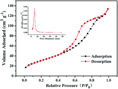 |
| | Fig. 7 N2 adsorption–desorption isotherms and BJH pore distribution curves (inset) of TiO2/GO-8 nanocomposites. | |
3.2 Photocatalytic performance of TiO2/GO nanocomposites
3.2.1. Photocatalytic reduction mechanism of TiO2/GO nanocomposites. The photocatalytic reduction mechanism of TiO2/GO nanocomposites is shown in Fig. 8. First of all, the hydroxyl ion (OH−), oxygen (O2), Cd2+ and Pb2+ in ROC are adsorbed onto the TiO2/GO surface. Under UV irradiation, TiO2 absorbs UV light energy and the electrons move up to a higher energy level. Meanwhile, the electron–hole pairs will be generated (eqn (1)). Electrons (e−) are transferred from the conduction band of TiO2 to GO, which could enhance the photocatalytic activity of TiO2. As a result, O2 will be reduced to superoxide radical anion (·O2−) due to the strong reduction ability of photogenerated electrons (eqn (2)). Meanwhile, Cd2+ and Pb2+ adsorbed on the surface of GO will be reduced to Pb and Cd, respectively (eqn (4) and (5)). Moreover, there might be another way to remove Pb2+ by the oxidation method. Residual holes within the valence band of TiO2 would react with OH− and H2O to form hydroxyl radicals (·OH) for oxidation reactions (eqn (5) and (6)). Hydroxyl radicals can oxidize Pb2+ to Pb4+, which will precipitate in the form of PbO2 (eqn (7)). Finally, reduced and oxidized products will fall off the surface of TiO2/GO nanocomposites.| | |
TiO2/GO + hv → e− + h+
| (1) |
| | |
2·OH + Pb2+ → PbO2 + 2H+
| (7) |
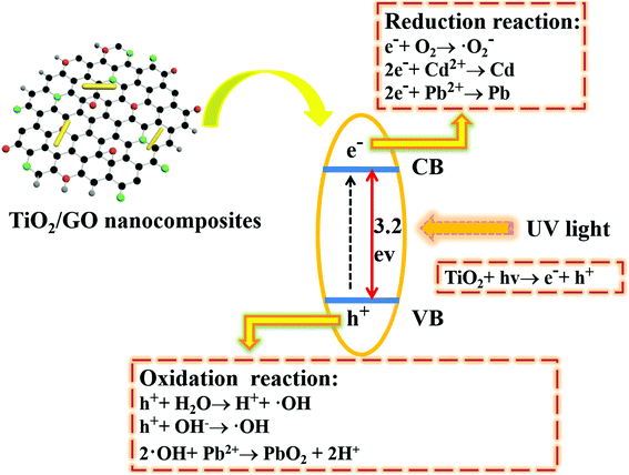 |
| | Fig. 8 Schematic diagram of the charge transfer and separation in the TiO2/GO nanocomposites under UV light irradiation and the main steps to reduce heavy metal ions. | |
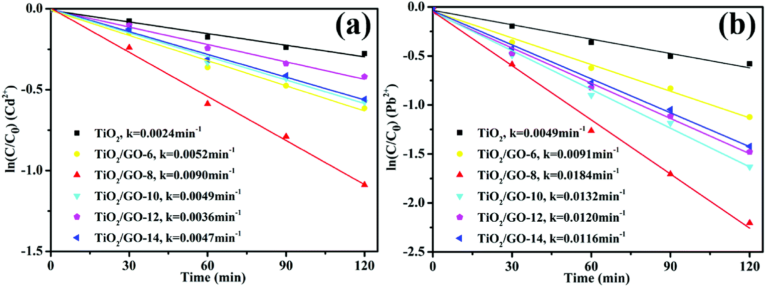
3.2.2 Photoreduction activity of materials. Fig. 9 depicts the corresponding kinetic curves for both Cd2+ and Pb2+ photocatalytic reduction followed a pseudo-first-order kinetic equation with a simplified Langmuir–Hinshelwood mode. According to the calculated rate constants of Cd2+ (Fig. 9a), the corresponding reaction rate of TiO2/GO-8 (k = 0.0090 min−1) was 3.75 times higher than that of pure TiO2 (k = 0.0024 min−1). Besides, the calculated rate constants of Pb2+ was shown in Fig. 9b, similarly, the reaction rate of TiO2/GO-8 (k = 0.0184 min−1) was about 3.75 times higher than that of pure TiO2 (k = 0.0049 min−1). It can be seen that TiO2/GO nanocomposites exhibited relative larger adsorption capacity than pure TiO2.
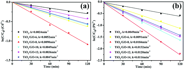 |
| | Fig. 9 The corresponding fitted reaction kinetic curves of TiO2/GO nanocomposites with different amount of GO (pH = 6.0; −ln(C/C0) = kt, where C/C0 is the concentration of heavy metal ions, k is the apparent first-order rate constant, t is the irradiation time). | |
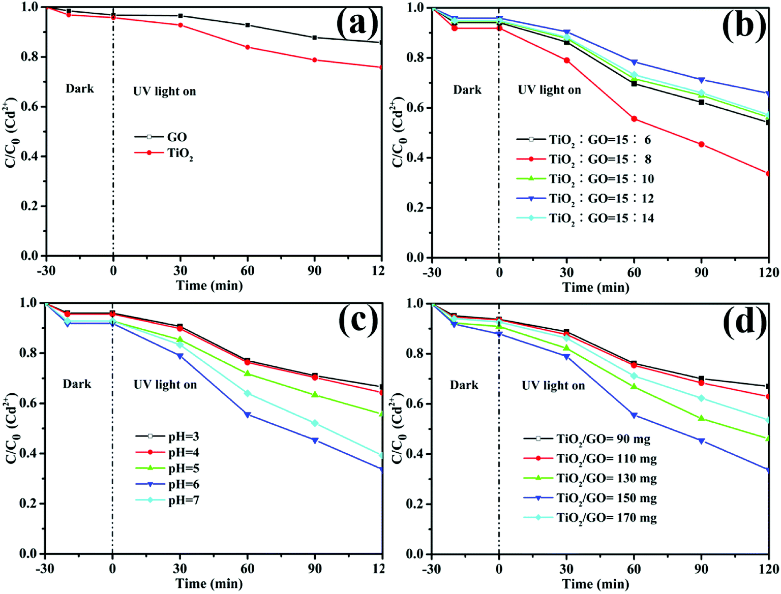
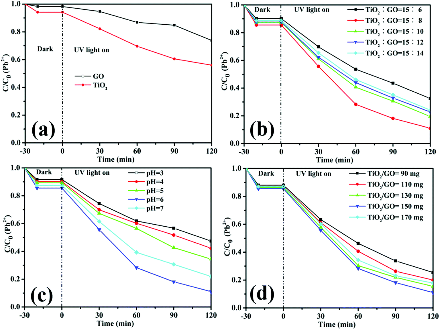
The dark absorption and photoreduction activity of Cd2+ and Pb2+ using TiO2, GO and TiO2/GO nanocomposites was studied. Fig. 10 and 11 illustrate the concentration of Cd2+ and Pb2+ under various operating conditions, respectively. The initial concentrations of Cd2+ and Pb2+ in the ROC were 0.155 and 0.334 mg L−1, respectively. Fig. 10a and 11a shows that both pure GO and TiO2 could reduce Cd2+ and Pb2+ to some extent. Moreover, compared with pure GO and TiO2, the photoreduction capability was increased significantly with the catalysis of TiO2/GO nanocomposites. There was a large specific surface area on TiO2/GO nanocomposites and the combination of GO with TiO2 led to a stronger redox ability. Besides, the functional groups of TiO2/GO nanocomposites outnumbered the unmodified TiO2, which helps the TiO2/GO nanocomposites contact fully with the heavy metal ions. Furthermore, GO had a stronger adsorption of Pb2+ than Cd2+, resulting in the higher photoreduction of Pb2+ than Cd2+. This is probably attributed to the selective adsorption of the specified heavy metal ion by GO.47
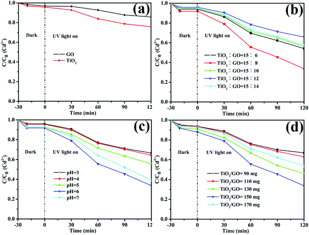 |
| | Fig. 10 The relative concentration of Cd2+ under different conditions. (a) Pure TiO2 and GO, (b) the mass ration of TiO2 to GO in TiO2/GO nanocomposites, (c) pH value and (d) the amount of TiO2/GO. | |
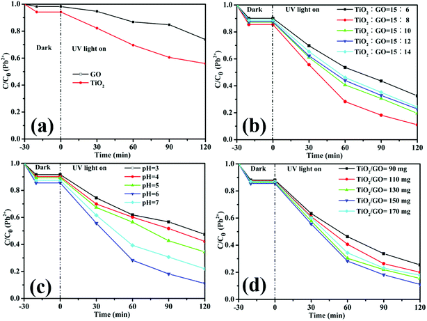 |
| | Fig. 11 The relative concentration of Pb2+ under different conditions. (a) Pure TiO2 and GO, (b) the mass ration of TiO2 to GO in TiO2/GO nanocomposites, (c) pH value and (d) the amount of TiO2/GO. | |
Fig. 10b and 11b illustrate that the photoreduction activities of Cd2+ and Pb2+ obtained at the mass ratio of TiO2 to GO of 15:8 are higher than those obtained at other mass ratios of TiO2 to GO. With the amount of GO increasing, the reaction rates and photoreduction activities of TiO2/GO nanocomposites increase firstly and then decrease. The TiO2/GO-8 nanocomposites displayed the highest photoreduction capability with maximal apparent rate constant k values of 0.0090 (Cd2+) and 0.0184 (Pb2+) min−1. GO created a large surface area to improve the photocatalytic activity of TiO2. When GO was introduced into TiO2, the absorbance edge of TiO2 shifted to the higher wavelength region due to the formation of Ti–O–C bond in TiO2/GO nanocomposites, which helps to enhance the absorption ability of the photocatalysts.21 This indicates that the introduction of appropriate amount of GO has a positive influence on improving photoreduction performance of nanocomposites. However, further increasing the amount of GO lead to a significant decrease of photoreduction activity, probably owning to the reduced catalytic active sites and increased charge carriers recombination rate caused by excessive GO loading. The higher GO content introduced into TiO2 could increase the probability of collision between photogenerated electron–hole pairs, which would increase the charge carrier recombination rate increased from the conduction band to valence band and ultimately lower the photocatalytic performance of the catalyst.32 Besides, in the TiO2/GO-10, TiO2/GO-12 and TiO2/GO-14 nanocomposites, excess black GO would absorb a lot of light, which inhibited the efficient absorption of UV irradiation light by TiO2.48 Therefore, the optimal dosage of GO is 80 mg in the hydro-thermal reaction to prepare TiO2/GO nanocomposites, and the corresponding product (TiO2/GO-8 nanocomposites) presented the best photoreduction activity. It showed a significant synergetic effect of GO with TiO2 in the photoreduction process.
Besides, the effect of pH on the reduction of Cd2+ and Pb2+ was shown in Fig. 10c and 11c, respectively. It is obvious that the pH value had a great influence on the removal rate of heavy metal ions. One reason is that the acidity can influence the surface active sites of TiO2/GO nanocomposites. Another reason is that the pH value was related to the state of heavy metal ions in the solution. Clearly, the photoreduction activity of Cd2+ and Pb2+ were both improved by increasing the pH value to 6. However, further increasing the value of pH will bring about a decrease of photoreduction activity, probably owning to that both ions would be hydrolyzed to produce hydroxide precipitation.49 Therefore, the optimum pH is 6 for photoreduce Cd2+ and Pb2+.
As shown in Fig. 10d and 11d, the photoreduction activity of Pb2+ and Cd2+ obtained at the TiO2/GO nanocomposites dosage of 150 mg are higher than those obtained at other photocatalyst dosages. The results may be explained by the surface active sites of TiO2/GO nanocomposites and the phenomenon of light scattering. Higher dosage might cause the aggregation of the photocatalyst, which could reduce the surface active sites of the TiO2/GO nanocomposites. Additionally, the increase of the photocatalyst dosage resulted in the light scattering phenomenon, which could reduce the efficiency of light radiation. Therefore, 150 mg of TiO2/GO nanocomposites exhibited the highest activity in photocatalytic reduction.
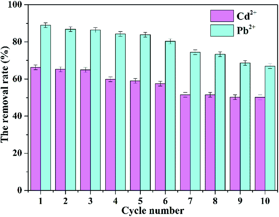
3.2.3 Photocatalytic stability of TiO2/GO nanocomposites. The performance stability of photocatalyst is an important indicator for its practical application. Therefore, the photocatalytic stability of TiO2/GO nanocomposites was investigated. TiO2/GO-8 nanocomposite was chosen to reduce heavy metal ions in the cycle reaction process, since TiO2/GO-8 nanocomposites presented the best photoreduction activity. A predetermined amount of photocatalyst was added to the original ROC wastewater. The proportion of photocatalyst to ROC wastewater was same with the first photocatalytic experiments. H2SO4 and NaOH were used to adjust the pH value of wastewater to 7. Other experimental procedures were the same as before. The photocatalyst was separated from the reaction mixture by centrifugation at 5000 rpm for 6 min after each photocatalytic experiment and then dried in vacuum at 60 °C for 6 h to recover it. After 10 cycles, TiO2/GO nanocomposites retained 50.13% yield photocatalytic reduction of Cd2+. Simultaneously, TiO2/GO nanocomposites also maintained a satisfactory removal rate of Pb2+, which was still over 66.98%. The corresponding results were shown in Fig. 12. The results showed that TiO2/GO nanocomposites possessed excellent photocatalytic stability.
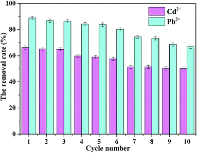 |
| | Fig. 12 Recycling tests of Cd2+ and Pb2+ for TiO2/GO-8 nanocomposites. | |
4 Conclusion
In this study, GO, TiO2 and TiO2/GO nanocomposites photocatalysts were synthesized by means of Hummers, hydro-thermal and freeze-drying method, respectively. Moreover, the characterization showed that the TiO2/GO nanocomposites had stable structures and good photocatalytic activity. Especially, GO could limit the recombination of photo-generated electron–hole pairs effectively and enhance the photocatalytic activity of TiO2 remarkably. In the photocatalytic reduction experiments, the TiO2/GO nanocomposites showed a higher photocatalytic activity than pure GO and TiO2. TiO2/GO-8 exhibit the highest reaction rate and more than 66.32% Cd2+ and 88.96% Pb2+ were reduced using a 0.6 g L−1 concentration of TiO2/GO nanocomposites at the pH 6 after 120 min irradiation. The combination of GO and TiO2 promoted the reduction of heavy metal ions. In a word, TiO2/GO nanocomposites were a favorable photocatalyst for the reduction of heavy metal ions to reduce their toxicity in ROC. This study provides a feasible method to solve the problem that low concentration heavy metal ions are difficult to reduce in sewage, thereby benefitting the human health, social development, and the reuse of wastewater.
Conflicts of interest
There are no conflicts to declare.
Acknowledgements
This work was supported by the Natural Science Foundation of Shandong Province, China (Grant No. ZR2015EL044, ZR2013BL010) and SDUT & Zibo City Integration Development Project (Grant No. 2016ZBXC116).
References
- X. Wei, P. Gu and G. Zhang, Desalination, 2014, 352, 18–26 CrossRef CAS.
- J. Lu, L. Fan and F. A. Roddick, Chemosphere, 2013, 93, 683–688 CrossRef CAS PubMed.
- G. Naidu, S. Jeong, Y. Choi and S. Vigneswaran, J. Membr. Sci., 2016, 524, 565–575 CrossRef.
- H. Luo, H. Li, Y. Lu, G. Liu and R. Zhang, Desalination, 2017, 408, 52–59 CrossRef CAS.
- J. O. Tijani, O. O. Fatoba, O. O. Babajide and L. F. Petrik, Environ. Chem. Lett., 2016, 14, 27–49 CrossRef CAS.
- C. Jung, A. Son, N. Her, K. D. Zoh, J. Cho and Y. Yoon, J. Ind. Eng. Chem., 2015, 27, 1–11 CrossRef CAS.
- M. Gmurek, M. Olak-Kucharczyk and S. Ledakowicz, Chem. Eng. J., 2017, 310, 437–456 CrossRef CAS.
- M. Llorca, M. Badia-Fabregat, S. Rodríguez-Mozaz, G. Caminal, T. Vicent and D. Barceló, Chemosphere, 2017, 184, 1054–1070 CrossRef CAS PubMed.
- M. A. P. Cechinel, S. M. A. G. U. D. A. Souza and A. U. D. Souza, J. Cleaner Prod., 2014, 65, 342–349 CrossRef CAS.
- C. F. Carolin, P. S. Kumar, A. Saravanan, G. J. Joshiba and M. Naushad, J. Environ. Chem. Eng., 2017, 5, 2782–2799 CrossRef CAS.
- C. Xiong, W. Wang, F. Tan, F. Luo, J. Chen and X. Qiao, J. Hazard. Mater., 2015, 299, 664–674 CrossRef CAS PubMed.
- R. Daghrir, P. Drogui and D. Robert, Ind. Eng. Chem. Res., 2013, 52, 3581–3599 CrossRef CAS.
- W. K. Jo, S. Kumar, M. A. Isaacs, A. F. Lee and S. Karthikeyan, Appl. Catal., B, 2016, 201, 159–168 CrossRef.
- G. Peng, A. Li, D. D. Sun and W. J. Ng, J. Hazard. Mater., 2014, 279, 96–104 CrossRef PubMed.
- C. Lai, M. M. Wang, G. M. Zeng, Y. G. Liu, D. L. Huang, C. Zhang, R. Z. Wang, P. Xu, M. Cheng, C. Huang, H. P. Wu and L. Qin, Appl. Surf. Sci., 2016, 390, 368–376 CrossRef CAS.
- L. Lin, H. Wang, W. Jiang, A. R. Mkaouar and P. Xu, J. Hazard. Mater., 2017, 333, 162–168 CrossRef CAS PubMed.
- Z. Zhao, J. Sun, S. Xing, D. Liu, G. Zhang, L. Bai and B. Jiang, J. Alloys Compd., 2016, 679, 88–93 CrossRef CAS.
- M. C. Rosu, M. Coros, F. Pogacean, L. Magerusan, C. Socaci, A. Turza and S. Pruneanu, Solid State Sci., 2017, 70, 13–20 CrossRef CAS.
- Q. Deng, C. Chen, Q. Lei, Ji. Liang, T. Zhang and J. Jiang, RSC Adv., 2018, 8, 23382–23389 RSC.
- J. Wang, R. Liu and X. Yin, J. Chem. Eng., 2018, 63, 409–416 CrossRef CAS.
- R. Atchudan, T. Edison, S. Perumal, D. Karthikeyan and Y. Lee, J. Photochem. Photobiol., A, 2017, 333, 92–104 CrossRef CAS.
- J. S. Lee, K. H. You and C. B. Park, Adv. Mater., 2012, 24, 1084–1088 CrossRef CAS PubMed.
- Y. Sang, Z. Zhao, J. Tian, P. Hao, H. Jiang, H. Liu and J. P. Claverie, Small, 2014, 10, 3775–3782 CrossRef CAS PubMed.
- L. Fan, X. Li, X. Song, N. Hu, D. Xiong, A. Koo and X. Sun, ACS Appl. Mater. Interfaces, 2018, 10, 2637–2648 CrossRef CAS PubMed.
- X. Song, X. Li, Z. Bai, B. Yan, D. Xiong, L. Lin, H. Zhao, D. Li and Y. Shao, Carbon, 2018, 133, 14–22 CrossRef CAS.
- D. Xiong, X. Li, Z. Bai and S. Lu, Small, 2018, 14, 1703419 CrossRef PubMed.
- W. Peng, H. Li, Y. Liu and S. Song, J. Mol. Liq., 2017, 230, 496–504 CrossRef CAS.
- Z. Li, F. Chen, L. Yuan, Y. Liu, Y. Zhao, Z. Chai and W. Shi, Chem. Eng. J., 2012, 210, 539–546 CrossRef CAS.
- L. Cui, Y. Wang, L. Gao, L. Hu, L. Yan, Q. Wei and B. Du, Chem. Eng. J., 2015, 281, 1–10 CrossRef CAS.
- F. Fang, L. Kong, J. Huang, S. Wu, K. Zhang, X. Wang, B. Sun, Z. Jin, J. Wang, X. Huang and J. Liu, J. Hazard. Mater., 2014, 270, 1–10 CrossRef CAS PubMed.
- R. Raliya, C. Avery, S. Chakrabarti and P. Biswas, Appl. Nanosci., 2017, 7, 253–259 CrossRef CAS.
- H. Yadav and J. Kim, J. Alloys Compd., 2016, 688, 123–129 CrossRef CAS.
- V. Bhatia, G. Malekshoar, A. Dhir and A. Ray, J. Photochem. Photobiol., A, 2017, 332, 182–187 CrossRef CAS.
- M. Nawaz, W. Miran, J. Jang and D. S. Lee, Appl. Catal., B, 2017, 203, 85–95 CrossRef CAS.
- Z. Zhang, J. Zhao, J. Zhou, Y. Zhao, X. Tang and S. Zhuo, Energy Storage Mater., 2017, 8, 35–41 CrossRef.
- W. Liu, J. Cai, Z. Ding and Z. Li, Appl. Catal., B, 2015, 174–175, 421–426 CrossRef CAS.
- J. Ge, Y. Ping, G. Liu, G. Qiao, E. J. Kim and M. Wang, Mater. Lett., 2016, 181, 216–219 CrossRef CAS.
- P. Gao, Z. Liu, M. Tai, D. D. Sun and W. Ng, Appl. Catal., B, 2013, 138, 17–25 CrossRef.
- B. Qiu, Y. Zhou, Y. Ma, X. Yang, W. Sheng, M. Xing and J. Zhang, Sci. Rep., 2015, 5, 8591–8596 CrossRef CAS PubMed.
- J. Hu, H. Li, Q. Wu, Y. Zhao and Q. Jiao, Chem. Eng. J., 2015, 263, 144–150 CrossRef CAS.
- J. Fu, G. Kyzas, Z. Cai, E. Deliyanni, W. Liu and D. Zhao, Chem. Eng. J., 2018, 335, 290–300 CrossRef CAS.
- W. Tang, G. Zeng, J. Gong, J. Liang, P. Xu, C. Zhang and B. Huang, Sci. Total Environ., 2014, 468–469, 1014–1027 CrossRef CAS PubMed.
- R. Atchudan and A. Pandurangan, Microporous Mesoporous Mater., 2013, 167, 162–175 CrossRef CAS.
- W. Yang, Y. Li and Y. Lee, Appl. Surf. Sci., 2016, 380, 249–256 CrossRef CAS.
- Y. Yang, L. Luo, M. Xiao, H. Li, X. Pan and J. Fang, Mater. Sci. Semicond. Process., 2015, 40, 183–193 CrossRef CAS.
- J. Henych, V. Štengl, A. Mattsson, J. Tolasz and L. Österlund, J. Hazard. Mater., 2018, 359, 482–490 CrossRef CAS PubMed.
- W. Peng, H. Li, Y. Liu and S. Song, J. Mol. Liq., 2017, 230, 496–504 CrossRef CAS.
- Y. Zhu, Y. Wang, W. Yao, R. Zong and Y. Zhu, RSC Adv., 2015, 5, 29201–29208 RSC.
- J. Zhao, Y. Niu, R. Ben, H. Chen, S. Zhang, J. Jin and Y. Zhang, Chem. Eng. J., 2018, 347, 574–584 CrossRef CAS.
|
| This journal is © The Royal Society of Chemistry 2018 |
Click here to see how this site uses Cookies. View our privacy policy here. 
 Open Access Article
 This Open Access Article is licensed under a Creative Commons Attribution-Non Commercial 3.0 Unported Licence
 *a
*a