Poly(oxymethylene) dimethyl ether synthesis – a combined chemical equilibrium investigation towards an increasingly efficient and potentially sustainable synthetic route†
Received
12th August 2016
, Accepted 16th December 2016
First published on 16th December 2016
Abstract
Polyoxymethylene dimethyl ethers (denoted hereon as OME) are potential sustainable fuels (e.g. as a diesel substitute). In this paper, the fundamental analysis of a potentially, sustainable synthetic OME system is presented (i.e. based on CH3OH synthesised from H2 and recycled CO2). In this context, a multicomponent thermodynamic vapour–liquid equilibrium model, based on CH3OH as the educt and source of H2CO for OME synthesis, is described. A thermodynamic equilibrium mathematical model for this complex (i.e. a 29 reaction network) CH3OH–H2CO equilibrium system is presented, capable of solving the sequential chemical and phase equilibrium, importantly considering all components in the reaction system including poly(oxymethylene) hemiformals and poly(oxymethylene) glycols. A theoretical efficiency evaluation indicates that the proposed anhydrous route is potentially more attractive than the conventional synthesis (i.e. based on dimethoxymethane and trioxane). To substantiate these theoretical investigations, a complimentary experimental batch OME synthesis is also presented, providing validation for the presented thermodynamic model. An initial kinetic analysis of the OME synthesis over different commercial catalysts is also highlighted. Our presented findings reliably describe the synthesis equilibrium with respect to our experimentally obtained results. The presented work supports further an operating OME synthesis framework based on CH3OH and H2CO and highlights the requirement for innovative process design regarding feed preparation, reactor technology, and product separation/fractions recycling.
Introduction
To counteract the negative impacts of greenhouse gas (GHG) emissions, the utilisation of CO2 as a carbon source/precursor is of critical importance in the production of chemicals, materials and fuels, particularly if society is to successfully achieve GHG reduction targets at the global (e.g. COP21) and national levels (e.g. 80% reduction by 2050 in Germany, relative to 1990).1 One of the most challenging sectors in this context is the mobility sector, which accounts for ca. 23% of global energy-related CO2 emissions (6.7 Gt (CO2) in 2010).2 Therefore liquids fuel production based on CO2 (e.g. suitable for current and future mobility modes) could play an important role in reaching emission targets in transport applications provided they can be produced sustainably and integrated with renewable energies. In this context, there have been a number of recent reports describing the conversion CO2 typically with H2 (e.g. via thermo- or electrochemical routes), followed by upgrading if necessary, to produce high purity “clean” fuels and platform chemicals.3–7 These products, typically oxygenates including methanol, dimethyl ether and more recently members of the poly(oxymethylene) dimethyl ether family (denoted hereon as MeOH, DME and OME respectively) are characterised by interesting intrinsic combustion properties (e.g. significantly reduced soot and particulate matter production), when employed in pure form or blended with conventional fuels.8–10
Regarding the low molecular weight oxygenates, MeOH, DME and dimethoxy methane (OME1) have potential disadvantages as fuels due to high vapour pressures and low viscosity, whilst conventional engines must typically be modified to use this fuels (e.g. to avoid vapour lock or injection system problems associated with DME use).8,11 Conversely, OME oligomers (chemical formula H3C–O–(CH2O)n–CH3 where n = 3–5) have successfully been blended with conventional diesel at 5–30% vol. and the resulting mixed fuel used without engine modification.12 Application of these fuel blends enhanced the cetane number and significantly reduced soot formation during combustion.13–16 These use of these fuel blends also improved overall combustion efficiency, the result of enhanced air to fuel ratios, since the OMEn (where n = 3–5) fraction contains ca. 48% covalently incorporated oxygen.
Given the ability to control in principle the oligomer chain length and in turn the resulting liquid polarity, OME have also been considered as sustainable solvents (e.g. if they are sourced from captured CO2/renewable H2), complementing the current use of OME1 as a common industrial organic solvent. Along similar lines, OME5 has been proposed, based on computation modelling studies to be particularly suitable for CO2 absorption (e.g. from natural gas streams).17 In addition, OMEs are known to present limited or no health or environmental hazards.13,14
The synthesis of OME requires a methyl end group supplier or capping source (e.g. MeOH, DME, OME1) and a formaldehyde (FA) monomer supplier (e.g. monomeric FA, poly(oxymethylene)glycols as a concentrated solution of FA in water, para-formaldehyde (p-FA), or trioxane (TRI)). Based on the selected feed, an aqueous or anhydrous synthesis route can be used, which highly influences the end product distribution and side product formation (Fig. 1). All routes are based on MeOH as the platform alcohol, which may be produced, amongst other pathways, through the direct hydrogenation of CO2, where H2 is supplied from renewable energy powered electrolysis.3,4,6,18 Therefore, the optimisation of a complete MeOH-based, OME synthesis chain facilitates the synthesis of quasi-CO2-neutral OME (e.g. for fuel or chemical industry applications).
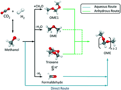 |
| | Fig. 1 Synthetic routes to polyoxymethylene dimethyl ethers (OME) based on the synthesis of CH3OH from recycled CO2 and sustainable H2via aqueous or anhydrous routes. | |
Current industrial synthesis routes (e.g. in China) to OME (where n > 2) are based on OME1 plus TRI or p-FA systems, with these precursors derived from conventional feedstocks (e.g. gas-to-liquid, coal gasification, etc.).19–27 Using MeOH and FA directly in OME synthesis could potentially provide a more efficient route to OME, as the energy intensive synthesis of TRI, p-FA or OME1 could be avoided. In this context, previous reports by Zhang et al. demonstrate OME synthesis based on MeOH and FA over a Zr-modified γ-alumina catalyst in a fixed bed reactor, with the authors describing the kinetics of this system.28,29 Likewise Burger et al. studied the thermodynamics and kinetics of this OME synthetic system over a Amberlyst®-46 catalyst in a batch reactor.30,31 Complimentarily to these works, the following report describes a multiphase chemical equilibrium thermodynamic model for OME synthesis, that includes all components for a complex aqueous reaction system (Fig. 2). To assess and validate this developed model, batch autoclave experiments were also performed with results compared to those of previous reports. The presented results and the understanding derived from both a theoretical and experimental standpoint provides the fundamental basis for further improvements in OME synthesis as well as assisting continuous process development, importantly from a sustainable synthetic chain based on CO2 and H2.
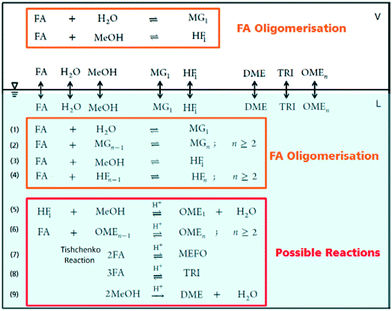 |
| | Fig. 2 OME synthesis reaction systems in liquid and vapour phases following a direct aqueous-based synthesis route. | |
Theory and background
Chemical reactions
The OME reaction system is a unique cascade based in the described case on two starting compounds, namely MeOH and FA and more than thirty components in equilibrium. The set of reactions that occur in this system and the corresponding distribution of components in each phase, following the direct aqueous-based synthesis route have been outlined (Fig. 2). In a previous report, Burger et al. explained the formation of poly(oxymethylene) hemiformals (denoted as HFn) HO–(CH2O)n–CH3 and poly(oxymethylene) glycols (denoted as MGn) HO–(CH2O)n–H in aqueous and methanolic FA solutions at values across the entire pH scale.30 In the absence of a catalyst, the majority of monomeric FA is considered bound as either HFn or MGn, with the equilibrium lying strongly in favour of the products for eqn (1) to (4) (Fig. 2). However, HFn and MGn are known to be unstable (intermediates in this context) and can be expected to decompose relatively easily towards the reactants.
In contrast, the reactions governing OME formation only occur in acidic medium and a catalyst is required to establish an acceptable rate of reaction. In acidic medium, possible side reactions involving FA may also take place to yield methyl formate (MEFO) (eqn (7)) or TRI (eqn (8)). The formation of DME from MeOH is also known to be favoured using acidic conditions/catalysts (eqn (9)).7c In the gas phase, only reactions favouring short chain MG1 and HF1 formation are reported but other components exchanging between the gas and liquid phases may also influence the overall equilibrium composition distribution.
Reaction mechanism
Two reaction mechanisms are reported in literature for the aqueous phase synthesis of OME from MeOH and FA.31 The reaction pathway is believed to proceed through an addition reaction between monomeric FA and OME oligomers as they are formed in acidic media (eqn (10) and (11)). Previous literature indicates that acetalisation of HFn dominates for the OME chain growth as in eqn (3), (4) (Fig. 2) and (12).31| |  | (10) |
| |  | (11) |
| |  | (12) |
Wang et al. analysed this mechanism using density functional theory (DFT) combined with experimental investigations over sulfonic acid functionalized ionic liquids.32 It was reported that the formation of HF1 is energetically favourable over other proposed pathways and that OME chain growth proceeds through addition of monomeric FA to the forming HFn−1 and terminating based on capping the formed carbocations with MeOH. During kinetic investigations, it was reported that the simultaneous formation of long chain OME was observed with no sign of delay due to sequential chain growth,31 and therefore an acetalisation mechanism is a more probable description of the system; an important consideration regarding the establishment of reliable equilibrium models based on a stoichiometric approach.
Theoretical efficiency
In evaluating the theoretical efficiency of an OME production process based on MeOH (e.g. derived from CO2 and H2) two routes are compared. 1) A standard or conventional route; this starts with MeOH synthesis followed by FA production via (partial) oxidation of MeOH (i.e. the FORMOX/BASF process) to yield aqueous solutions of FA.33 The resulting solution is concentrated and trimerized over an acid catalyst to produce TRI in a complex energy intensive distillation process.33,34 TRI or concentrated FA then reacts with MeOH to yield OME1. Finally, OME1 and TRI are selectively converted to higher OMEs (n ≥ 2); 2) an alternative pathway, as adopted in this work, proceeds based on MeOH dehydrogenation to anhydrous FA, an excellent feed for direct OME synthesis. Using a basic thermodynamic evaluation (Fig. 3), the respective efficiencies of these routes are compared on a basis of 1 kg (OME4) product. These calculations use the higher heating values (HHV) of the components and a simple stoichiometric evaluation. Even though the efficiency losses through the synthesis steps – more pronounced in route 1 (conventional) – are not regarded in this simplified calculation, the efficiency of route 2 (direct aqueous) is significantly higher. The direct synthesis of OME from MeOH and FA in route 2 requires 22% less H2 than route 1, consequently enhancing the potential theoretical efficiency of route 2 by 20% (with respect to route 1). In addition, the technological simplicity and synthesis energy demand of route 2 is to be noted (e.g. as compared to route 1), providing further motivation to investigate this synthesis pathway.
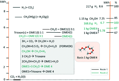 |
| | Fig. 3 Thermodynamic theoretical efficiency evaluation of proposed OME synthesis starting from CO2 and H2O (i.e. as H2 source). Conventional route 1 (black) uses a partial oxidation (i.e. FORMOX) process and TRI, compared route 2 (green; i.e. the direct aqueous route) with FA production based on MeOH dehydrogenation and direct conversion to OME4. | |
Multiphase model of the chemical equilibrium
The model algorithm
To solve chemical equilibrium challenges it is necessary to combine mass balances with reaction equilibria criteria. Stoichiometric methods described by O'Connell et al. are applied in this investigation.35 In this case, a set of R reactions (29 reactions in the present work; Fig. 4) are solved for R-number extents of reactions (ξ) within an iterative loop, following a Newton–Raphson approach. For this algorithm the reactions have to be well specified through their stoichiometric coefficients (ν). For a two phase reaction system approaching a chemical-phase equilibrium state, the following equilibrium criteria should be fulfilled (eqn (13) and (14)).| |  | (13) |
| |  | (14) |
where μi is the chemical potential of component i, vij is the stoichiometric coefficient of every component i in reaction j, fv,li is the fugacity of i components in a certain phase, yi and xi are the mole fractions in vapour and liquid phase respectively and γi is the activity coefficient of i components in liquid phase. At certain operating conditions (T, P and feed amount), the two equilibrium relations are sequentially solved, thus the chemical equilibrium compositions are also at vapour/liquid phase equilibrium (VLE). Taking into account the relatively low pressure, eqn (14) is developed considering an ideal behaviour of the gas phase as well as pressure independence of the fugacity in the liquid phase.
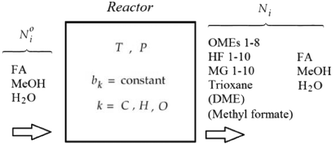 |
| | Fig. 4 The chemical equilibrium component system for a single phase OME aqueous route synthesis. | |
Model inputs
Expanding the chemical equilibrium criteria in eqn (13) towards the form of either eqn (15) or (16) highlights the required inputs needed to solve the problem. Eqn (15) and (16) are the same construction as eqn (13), but expanded in terms of the standard Gibbs energy of formation  or the reaction equilibrium constant (ln
![[thin space (1/6-em)]](https://www.rsc.org/images/entities/char_2009.gif) Kj). Ψj represents the numerical value of the function in every iteration step, which must meet a value below a pre-set tolerance.
Kj). Ψj represents the numerical value of the function in every iteration step, which must meet a value below a pre-set tolerance.| |  | (15) |
| |  | (16) |
Solving the chemical equilibrium using the target function (eqn (15)), requires the definition of  for each component i corrected at TReaction. Thus, a temperature correction relation (defined as a function of the standard enthalpy of formation
  and the standard heat capacity
  ), needs to be solved to transfer
  from standard T to the reaction condition.
It is important to note that since thermodynamic data for higher OME (n ≥ 2) nor HFn and MGn are currently defined in the literature, estimation of these values are provided based on functional group contributions first used to define the required properties (please refer to Table S1† for further details). Although estimation methods for the required properties are quite reliable, the small error associated for each property of each component accumulates and can significantly influence the equilibrium composition calculation. Poling et al. reported the sensitivity of Kj with deviations in  due to the exponential relation between them.36 On the other hand the equilibrium constant Kj is a function of temperature and can be determined experimentally (eqn (17); Table S2† for values of A and B constants used in calculation of Kj).30,37
| |  | (17) |
For phase equilibrium calculations, eqn (14) can be solved as a normal flash calculation. The excess Gibbs energy of the liquid mixture is described by the modified UNIFAC group contribution method,38 using the same UNIFAC-group distribution and interactions parameters as Hahnenstein et al., and Schmitz et al.39 The UNIFAC groups considered in this investigation are the following: (CH2O)FA, (CH2O)OME, H2O, MeOH, OME1 and MG1 along with OH, CH2, CH3O, and CH2OH. Within these, the CH2O corresponding to FA is different than the oxymethylene groups in the OME structure. There are 10 groups in total, thus all the compounds present in the mixtures are a molecular arrangement of these groups (Tables S3 and S4† for details concerning UNIFAC-group assignment and group interaction parameters (amn)).
Modelling procedure
Fig. 4 illustrates the chemical equilibrium components in a single phase. The aim of the modelling is to find a combination of moles number (Ni) for every component i that meets the target function. Ni do not change arbitrarily, but is instead coupled through the stoichiometry of the reactions. The algorithm therefore solves for R-number of independent extents of reaction at kth step (Δξ(k)l), from which the next moles number (N(k+1)i) can be obtained (i.e.eqn (18)) until the target function is fulfilled. These changes are moderated by the damping factor, ζ.| |  | (18) |
The elementary mass balance (bk) represents the total amount of k = C, H and O atoms, which are constant throughout the whole calculation (i.e. the mass balance constraint), defined by the initial mole number (N0i), multiplied by the elementary matrix (aki) for k elements and i components (eqn (19)).
| |  | (19) |
With the pre-defined constraint and target functions, the algorithm functions through three steps: (1) an initialisation step – all input data is fed to the model and ε of the target function is defined. This step requires an initial estimation of the equilibrium composition Ni that agrees with the elementary mass balance bk; (2) Iterative loop solving is used to find Ni that meets the target function 15 (or 16). The value of Δξ(k)l is computed using a Taylor series expansion of the target function for the (K + 1)th iteration and truncating after the linear term.
where the Hessian matrix (
R ×
R)
Ωjl is defined as follows giving
eqn (20).
| |  | (20) |
Eqn (20) therefore can be then solved for R increments of Δξ(k)l. Step (3) is a convergence, whereby the routine finally ends when all Ψj (R × 1) < ε. A typical value for the tolerance could be between 10−4 and 10−5. After the chemical equilibrium loop converges, the phase equilibrium loop starts. Coupling with the phase equilibrium calculation does not impact significantly on the thermodynamic consideration and requires minimal additional computational effort. The chemical-phase criteria (i.e.eqn (13) and (14)), are solved by assuming that the reactions occur in one phase only. This assumption is supported by the fact that the chemical potentials (μi) are combinations of fugacities, and the phase equilibrium criteria requires the same value of fugacity for each component in all phases.35 The strategy to solve the chemical-phase calculation is described (Fig. 5). The initial mole number (Ni) overall compositions (zi) estimation are generated by assuming reaction in one phase only and solving the previous single-phase reaction equilibrium calculation.
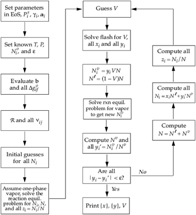 |
| | Fig. 5 Algorithm to compute chemical-phase equilibrium for several components i and reactions j at fixed T and P.24 | |
At the core of the iteration, the phase equilibrium is calculated by assuming a vapour fraction (V) as an initial estimation and then fitting the liquid and vapour compositions as a product of the Rachford-Rice equation.35 After determining the phase equilibrium, the mole numbers (Ni) are distributed into the calculated liquid (Nli) and vapour (Nvi) fractions, followed by a one-phase chemical equilibrium reaction performed considering an appropriate reaction phase to generate new Nvi (or Nli) values. Thus new yi (or xi) are iteratively improved until the compositions do not vary more than the chosen tolerance (ε) conserving the elementary mass balance.
Experimental
Chemicals and materials
Methanol (ROTISOLV®, purity >99.9%) and para-formaldehyde (n = 8–100, purity >95%) were purchased from Carl Roth GmbH. OME1 (purity ≥99%) was purchased from Sigma Aldrich. OME(n=2) (purity = 98.6%), OME3 (purity >99%), OME(n=4) (purity = 97%) were supplied by ASG Analytik Service GmbH. MEFO was purchased (97% purity (3% methanol)) from Alfa Aesar. Anhydrous sodium sulphite (Na2SO3; Bioultra grade, purity ≥98%) and 1.0 M HCl(aq) (Fluka standard grade solution) were purchased from Sigma Aldrich. All chemicals were used without further purification. Amberlyst™-36 (A36) (wet, Dp = 600–850 μm) was purchased from Rohm and Haas.21 DOWEX™ 50WX2 (DW50X2) (Dp = 37–74 μm) was purchased from DOW chemicals. Catalysts were dried overnight at 100 mbar under vacuum at 70 °C before use. Reaction mixtures were prepared by dissolving p-FA in MeOH at a p-FA/MeOH ratio of 1.5 (g g−1) corresponding to maximum FA solubility in methanolic solution. p-FA was dissolved by stirring and heating gradually for 4 h until reaching 80 °C. The solution was then left overnight at this temperature until a clear solution was obtained.40
Analysis
The quantitative analysis of the obtained product mixtures was performed using an Agilent 7890A gas chromatograph equipped with a flame ionisation detector (GC-FID) and auto sampler (0.4 μl sample volume). Samples were injected onto a DB-5 ms column (dimensions: 30 m × 250 μm × 0.5 μm) using He (g) as the carrier gas (flow: 4.1 mL min−1 at ca. 2 bar). The GC inlet temperature was set at 270 °C and operated in split mode (split ratio = 20). Chromatograms were obtained using a programmed oven temperature ramp (i.e. 35 to 270 °C, over 16 min). Calibration of the GC was achieved using pure OME1, OME(n=2–4) and standard mixtures of the pure components in MeOH. For MEFO, a 97% purity sample was used. OME5 was calibrated based on extrapolation and relating the chromatogram area per mass fraction as a linear function of carbon number in the OME molecule.30 As a complimentary qualitative analysis, an Agilent 6890A GC was also employed equipped with a CP-SIL5 (30 m × 8 μm) column and a Thermal Conductivity Detector (TCD). Samples were analysed using He as the carrier gas, an oven temperature ramp of 40 to 280 °C, and a column pressure ramp of 35–60 psi. FA was analysed based on a Na2SO3 volumetric titration method, using 1 M HCl(aq) as titre and thymolphthalein as indicator.41 The absolute deviation between the FA content measured in this work and the available literature experimental measurements, as well as the simulation results was ≤2%.
Experimental setup
To perform the acid catalysed synthesis of OME, an autoclave with 500 mL volume was used, equipped with a stainless steel reactor cylinder (Pmax = 100 bar). Reaction temperature was controlled using a fixed electrical heating jacket and integrated thermocouple (i.e. K-type thermocouple; accuracy ± 1.5 K). An integrated magnetic stirrer was also used (Fig. 6). Pressure was measured using a diaphragm pressure indicator (accuracy ± 0.24 bar) a cylindrical sintered stainless steel (AISI 316TI) filter (F1) with 10 μm pore size is mounted on the sampling line and positioned near to the reactor base to assure sample withdrawal without catalyst particles. To cool the withdrawn samples, a quartz glass double jacket condenser connected to a thermal bath was used (cooling medium = Glysofor® (Wittig Umweltchemie)). A set of ball valves (BV) and needle valves (NV) was designed to allow feed and catalyst loading, sample withdrawal and pressure regulation in the reaction system (Fig. 6).
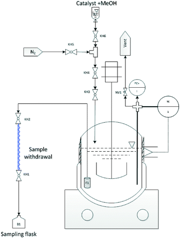 |
| | Fig. 6 Experimental setup used for OME synthesis equilibrium study i.e. (KH = Kugelhahn (german) / = BV = Ball Valve (BV) (english)). | |
Experimental procedure
The feed mixture was prepared externally in an electrically heated glass flask with a magnetic stirrer and reflux condenser to assure a clear reactant solution. Prior to loading, the autoclave was pre-heated and flushed with N2 until the reaction temperature of 80 °C was reached. The educts were then added to the autoclave reactor. The system was then sealed and brought to a steady state before initial sample withdrawal (t = 0 min). The catalyst (e.g. A36) was then loaded with ca. 10 mL MeOH in the loading line and introduced to the reactor using N2 flow (at ca. 3 bar). Samples were withdrawn for analysis at defined time intervals under reactor pressures. A flush of 3 mL was dispensed before each sample to rinse the sampling line. The reaction mixture was kept at constant T and stirring rate along the planned test interval (t ≥ 180 minutes). Samples analysed after longer test intervals showed constant equilibrium compositions. Experiments were performed using the two commercially available acid catalysts (i.e. D50WX2 and A36; Table 1).
Table 1 Summary of the parameters of the experimental runs
| Test # |
Test 1 |
Test 2 |
| Temperature (°C) |
80 |
80 |
| Pressure (bar) |
3.5 |
3.1 |
| Catalyst |
D50WX2 |
A36 |
| Cat. load (g gmix−1) |
0.5% |
0.5% |
| Reactant mix. load (g) |
200 |
200 |
|
p-FA/MeOH (g g−1) |
1.5 |
1.5 |
Results and discussion
Model validation
To validate the afore-described equilibrium model for OME synthesis, the set of experiments test-1 and test-2 (Table 1) were performed under the described reaction conditions. As comparative datasets, two previously published works performed at similar reaction conditions were selected; A) Burger et al. investigated the equilibrium experimentally under almost identical conditions, using Amberlyst®-46 as the catalyst (T = 75 °C, catalyst loading = 0.6% g gmix−1).30 B) Arnold et al. also reported OME synthesis experiments under the same conditions as reported here, using DOWEX®-50WX2 as catalyst (loading = 0.1% g gmix−1).40 In the current study, DME was excluded from the equilibrium mixture as it was not experimentally detected using the selected catalysts. The performance of the experiments under slightly higher pressure also aided to validate one phase and two phase simulations, as emphasised by an insignificant vapour fraction (V ≈ 0). The previously reported experiments (i.e.ref. 30 and 40) varied in the reactor setup, feed preparation method and experimental procedure, but all examples equilibrium was established, enabling a fair comparison.
The equilibrium compositions from the developed model in comparison with the results obtained from experiments test-1 and test-2, along with previously published data are compared (Fig. 7 and 8). Based on a parity plot analysis, a good agreement between all the considered components with model results was observed, except for MeOH (Fig. 8). The starting measured concentration of MeOH in previously reported literature was also found to vary from the measured initial MeOH concentration as in this work. In the equilibrium mixture, MeOH is mainly bound in the form of the unstable HFn. Depending on the analytical technique the free MeOH measured could vary (e.g. using GC), potentially providing an explanation for this observed deviation. Furthermore, the maximum arithmetic mean value of the absolute deviations between experimental measurements of OME in this work and previously published data did not exceed 0.5 wt%. These preliminary results demonstrate that the constructed model can reliably be employed to describe the equilibrium composition of this reaction system under different conditions.
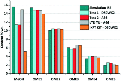 |
| | Fig. 7 Comparison of the experimental chemical equilibrium compositions of test-1 and test-2 with previous simulation and values from ref. 30 and 40. Reaction conditions: FA/MeOH (g g−1) = 1.5; 0.5% (0.1% for ref. 40) g gmix−1 catalyst load; T = 80 °C (75 °C for ref. 30). | |
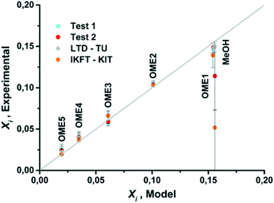 |
| | Fig. 8 Parity plot for mass fractions of OME1, OME(n=2–5) and MeOH for model and experimental results. | |
The reaction progress of experiments test-1 and test-2 are available as ESI† (test-1: Table S5, Fig. S1; test-2: Table S6, Fig. S2). The equilibrium compositions over D50WX2 were reached in ca. 20 min, while it took almost 1 h to be reached over the A36 catalyst. The observed higher reaction rates using the D50WX2 catalyst were attributed to the considerably smaller particle size and also the differing acid strengths/active site access (e.g. porosity).40 It is considered that these results provide a good basis for the kinetic study of different catalytic systems (i.e. to be investigated in the future).
Parametric study
After the model validation, parametric studies were performed to determine the influence of T, feed ratio and H2O content in the feed on the equilibrium composition. The OME formation reactions are slightly exothermic (Δhj ≈ −25 mol−1). Simulations for T indicate that the influence of this parameter on the equilibrium compositions at different FA/MeOH feed ratios are negligible regarding the production of OME(n=3–5), (i.e. when varying T by 35 °C; Fig. 9(a)).
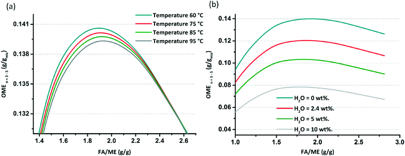 |
| | Fig. 9 (a) Effect of temperature increase on the OME (n = 3–5) composition at equilibrium. (b) Effect of water content in the feed (wt%) on the OME (n = 3–5) composition at equilibrium. | |
The influence of H2O content on the equilibrium composition distribution is more significant than T. Using an anhydrous feed doubles the target OME chain productivity when compared with a feed with a 10 wt% H2O content. In an MeOH/p-FA feed, ca. 2.4 wt% H2O is present, which limits the OME(n=3–5) yield (Fig. 9(b)). Referring to these results, the objective to achieve the highest OME(n=3–5) yield is defined to have a water free feed and operating as close as possible to a feed ratio of 1.9 FA/MeOH (g g−1). To establish this reaction, an innovative process is required to control the appropriate feed composition; whilst an OME synthesis reactor is required that enables operation in the vicinity of theoretical maximum. The maximum yield at equilibrium of the target OME chain (gOME(3−5) gproduct−1) under the optimum simulated conditions and anhydrous feed is ca. 14%, which is significantly low on an absolute basis. The main reasons for the low yield are (a) the limited conversion of MeOH and FA, since they also share equilibrium reactions to form MGn and HFn, (b) most of the converted educts to OME are in the OME1 and OME(n=2) components (>35% gOME(1−2) gproduct−1) and (c) the poor selectivity towards OME(n=3–5). It is proposed that the appropriate design and operation of a continuous process, which enables short OME oligomers to be recycled, supported by continuous H2O and OME(n=3–5) separation will lead to significantly enhanced overall yield. Furthermore, complimentary catalyst development, particularly given the highly polar environment of the equilibrium reactions and the importance of the interaction between the growing OME chain and supported acid catalyst, will presumably aid to improve overall synthesis productivity.
Conclusions
In this paper, the development, design and validation of the synthesis of OME based on MeOH and FA was investigated (e.g. as derived from a CO2 hydrogenation platform). The theoretical efficiency evaluation demonstrated that a proposed anhydrous route is potentially more attractive than a conventionally performed synthesis based on feeds of OME1 and TRI. A thermodynamic equilibrium mathematical model was developed and demonstrated to be capable of solving the sequential chemical and phase equilibrium, importantly considering all components in the reaction system including HFn and MGn. The equilibrium constants required for model convergence were successfully derived based on experimental and published data. Batch reaction experiments were performed using an autoclave-based test setup to enable the validation of the developed model. Two commercial polymer supported (Brønsted; namely –SO3H) acid catalysts were employed in the experimental evaluation of the equilibrium. Model results showed a strong and positive agreement with experimental results from this work and also with previously published datasets. After the model validation, a parametric study was performed to enable identification of the optimum operating conditions for OME synthesis, highlighting the significant impact of H2O content in the educts feed to the reactor and the importance of employing an anhydrous feed for maximising the yield of OME(n=3–5). Conversely, reaction temperature was found not to significantly influence the reaction equilibrium. A feed FA/MeOH (g g−1) ratio of approximately 1.9 was identified as potentially providing the highest yield of the target OME chain length (i.e. n = 3–5), although further work is required concerning process design if this high educt ratio is to be successfully achieved.
This study also highlights the operating framework for OME synthesis based on MeOH and FA and the necessity of innovative process regarding feed preparation, reactor technology, product separation/fractions recycling and potentially new catalyst development. With this understanding, a concept for an efficient continuous process for OME synthesis is to be developed and tested, whilst alternative feed mixtures are also being investigated within the framework of OME synthesis. Importantly, the presented results, synthetic model and system relies on the use of MeOH as educt, as a source of FA and in turn OME, providing a potentially sustainable route to higher value, higher energy content fuels, based on CO2 utilisation and renewable energy powered H2 production.
Acknowledgements
The project team is thankful to the “Leistungzentrum Nachhaltigkeit Freiburg” for funding.42 RJW is grateful to the Fraunhofer Society and Fraunhofer ISE for providing financial support via the Attract programme.
References
-
(a) M. Mikkelsen, M. Jørgensen and F. C. Krebs, Energy Environ. Sci., 2010, 3, 43–81 RSC;
(b) L. Mennicken, A. Janz and S. Roth, Environ. Sci. Pollut. Res., 2016, 23(11), 11386–11392 CrossRef CAS PubMed;
(c) J. Rogelj, M. den Elzen, N. Höhne, T. Fransen, H. Fekete, H. Winkler, R. Schaeffer, F. Sha, K. Riahi and M. Meinshausen, Nature, 2016, 534, 631–639 CrossRef CAS PubMed;
(d) N. S. Lewis, Energy Environ. Sci., 2016, 9, 2172–2176 RSC.
-
(a)
Intergovernmental Panel on Climate Change, Climate Change 2014: Mitigation of Climate Change: Working Group III Contribution to the IPCC Fifth Assessment Report, Cambridge University Press, Cambridge, UK, 2014 Search PubMed;
(b)
CO2 Emissions from Fuel Combustion, Highlight Report, International Energy Agency, Paris, France, 2015 Search PubMed.
-
(a) F. Pontzen, W. Liebner, V. Gronemann, M. Rothaemel and B. Ahlers, Catal. Today, 2011, 171(1), 242–250 CrossRef CAS;
(b) M. Aresta, A. Dibenedetto and A. Angelini, Chem. Rev., 2014, 114(3), 1709–1742 CrossRef CAS PubMed;
(c) A. J. Martín, G. O. Larrazábal and J. Pérez-Ramírez, Green Chem., 2015, 17, 5114–5130 RSC.
-
(a) H. Goehna and P. Koenig, CHEMTECH, 1994, 24(6), 36–39 CAS;
(b) M. Peters, B. Köhler, W. Kuckshinrichs, W. Leitner, P. Markewitz and T. E. Müller, ChemSusChem, 2011, 4, 1216–1240 CrossRef CAS PubMed;
(c) E. Frei, A. Schaadt, T. Ludwig, H. Hillebrect and I. Krossing, ChemCatChem, 2014, 6(6), 1721–1730 CrossRef CAS.
-
(a) W. Wang, S. Wang, X. Ma and J. Gong, Chem. Soc. Rev., 2011, 40, 3703–3727 RSC;
(b) G. A. Olah, Angew. Chem., Int. Ed., 2013, 52(1), 104–107 CrossRef CAS PubMed.
-
(a) O.-S. Joo, K.-D. Jung, I. Moon, A. Y. Rozovskii, G. I. Lin, S.-H. Han and S.-J. Uhm, Ind. Eng. Chem. Res., 1999, 38(5), 1808–1812 CrossRef CAS;
(b) R. W. Dorner, D. R. Hardy, F. W. Williams and H. D. Willauer, Energy Environ. Sci., 2010, 3, 884–890 RSC.
-
(a) K.-W. Jun, W.-J. Shen and K.-W. Lee, Bull. Korean Chem. Soc., 1999, 20(9), 993–998 CAS;
(b) T. Sakakura, J. C. Choi and H. Yasuda, Chem. Rev., 2007, 107(6), 2365–2387 CrossRef CAS PubMed;
(c) S. Abate, K. Barbera, G. Centi, P. Lanzafame and S. Perathoner, Catal. Sci. Technol., 2016, 6, 2485–2501 RSC.
- J. Burger, M. Siegert, E. Ströfer and H. Hasse, Fuel, 2010, 89(11), 3315–3319 CrossRef CAS.
-
Soot in Combustion Systems and Its Toxic Properties, ed. J. Lahaye and G. Prado, Springer, Boston, MA, USA, 1983 Search PubMed.
-
(a) W. Ying, L. Genbao, Z. Wei and Z. Longbao, Fuel Process. Technol., 2008, 89(12), 1272–1280 CrossRef;
(b) B. Lumpp, D. Rothe, C. Pastötter, R. Lämmermann and E. Jacob, MTZ Worldwide, 2011, 72, 198–203 CrossRef.
- M. Werner and G. Wachtmeister, MTZ Worldwide, 2010, 71(7–8), 70–72 CrossRef.
-
(a) Z. Wang, H. Liu, J. Zhang, J. Wang and S. Shuai, Energy Procedia, 2015, 75, 2337–2344 CrossRef CAS;
(b)
K. Gaukel, M. Härtl, G. Wachtmeister, J. Burger, W. Maus and E. Jacob, The Fuel OME2: An Example of the pathway to Emission Neutral Vehicles with Internal Combustion Engine, 37th Wiener Motorensymposium, Fortschritt-Berichte VDI, Reihe 12, Nr. 796, 2016 Search PubMed.
- A. Feiling, M. Münz and C. Beidl, ATZextra Worldwide, 2016, 21(11), 16–21 CrossRef.
-
W. Maus, E. Jacob, M. Härtl, P. Seidenspinner and G. Wachtmeister, Synthetic Fuels - OME1: A Potentially Sustainable Diesel Fuel, 35th Wiener Motorensymposium, Fortschritt-Berichte VDI, Reihe 12, Nr. 777, 2014 Search PubMed.
- M. Härtl, P. Seidenspinner, E. Jacob and G. Wachtmeister, Fuel, 2015, 153, 328–335 CrossRef.
- R. Wang, Z. Wu, Z. Qin, C. Chen, H. Zhu, J. Wu, G. Chen, W. Fan and J. Wang, Catal. Sci. Technol., 2016, 6(4), 993–997 CAS.
- J. Burger, V. Papaioannou, S. Gopinath, G. Jackson, A. Galindo and C. S. Adjiman, AIChE J., 2015, 61(10), 3249–3269 CrossRef CAS.
-
(a) W. Wang, S. Wang, X. Ma and J. Gong, Chem. Soc. Rev., 2011, 40, 3703–3727 RSC;
(b) E. V. Kondratenko, G. Mul, J. Baltrusaitis, G. O. Larrazábal and J. Pérez-Ramírez, Energy Environ. Sci., 2013, 6, 3112–3135 RSC;
(c) A. Goeppert, M. Czaun, J. P. Jones, G. K. S. Prakash and G. A. Olah, Chem. Soc. Rev., 2014, 43, 7995–8048 RSC.
- J. Burger, E. Ströfer and H. Hasse, Ind. Eng. Chem. Res., 2012, 51(39), 12751–12761 CrossRef CAS.
- W. H. Fu, X. M. Liang, H. Zhang, Y. M. Wang and M. Y. He, Chem. Commun., 2015, 51(8), 1449–1452 RSC.
- L. Wang, W.-T. Wu, T. Chen, Q. Chen and M.-Y. He, Chem. Eng. Commun., 2014, 201(5), 709–717 CrossRef CAS.
- J. Wu, H. Zhu, Z. Wu, Z. Qin, L. Yan, B. Du, W. Fan and J. Wang, Green Chem., 2015, 17(4), 2353–2357 RSC.
- Q. Wu, M. Wang, Y. Hao, H. Li, Y. Zhao and Q. Jiao, Ind. Eng. Chem. Res., 2014, 53(42), 16254–16260 CrossRef CAS.
- Y. Zhao, Z. Xu, H. Chen, Y. Fu and J. Shen, J. Energy Chem., 2013, 22(6), 833–836 CrossRef CAS.
- Y. Zheng, Q. Tang, T. Wang, Y. Liao and J. Wang, Chem. Eng. Technol., 2013, 36(11), 1951–1956 CrossRef CAS.
- Y. Zheng, Q. Tang, T. Wang and J. Wang, Chem. Eng. Sci., 2015, 134, 758–766 CrossRef CAS.
-
(a)
L. P. Lautenschütz, New findings in the optimisation of oxymethylene diethylether oligomer synthesis from dimethoxymethane
and trioxane/(“Neue Erkenntnisse in der Syntheseoptimierung oligomerer Oxymethylen-dimethylether aus Dimethoxymethan und Trioxan”), Dissertation, University of Heidelberg, URN:nbn:de:bsz:16-heidok-192102, 2015 Search PubMed;
(b) L. Lautenschütz, D. Oestreich, P. Seidenspinner, U. Arnold, E. Dinjus and J. Sauer, Fuel, 2016, 173, 129–137 CrossRef.
- J. Zhang, M. Shi, D. Fang and D. Liu, React. Kinet., Mech. Catal., 2014, 113(2), 459–470 CrossRef CAS.
- J. Zhang, D. Fang and D. Liu, Ind. Eng. Chem. Res., 2014, 53(35), 13589–13597 CrossRef CAS.
- N. Schmitz, F. Homberg, J. Berje, J. Burger and H. Hasse, Ind. Eng. Chem. Res., 2015, 54(25), 6409–6417 CrossRef CAS.
- N. Schmitz, J. Burger and H. Hasse, Ind. Eng. Chem. Res., 2015, 54(50), 12553–12560 CrossRef.
- F. Wang, G. Zhu, Z. Li, F. Zhao, C. Xia and J. Chen, J. Mol. Catal. A: Chem., 2015, 408, 228–236 CrossRef.
-
G. Reuss, W. Disteldorf, A. O. Gamer and A. Hilt, in Ullmann's Encyclopedia of Industrial Chemistry, Wiley-VCH Verlag GmbH & Co. KGaA, Weinheim, Germany, 2000, ch. Formaldehyde, p. 744 Search PubMed.
- T. Grützner, H. Hasse, N. Lang, M. Siegert and E. Ströfer, Chem. Eng. Sci., 2007, 62(18–20), 5613–5620 CrossRef.
-
J. P. O'Connell and J. M. Haile, Thermodynamics: Fundamentals for applications, Cambridge University Press, New York, USA, 2005 Search PubMed.
-
B. E. Poling, J. M. Prausnitz and J. P. O'Connell, The properties of gases and liquids, 5th edn, McGraw-Hill, New York, USA, 2001, ch. 4, p. 3.4 Search PubMed.
-
C. Kuhnert, Vapour-Liquid-Equilibrium in multicomponent Formaldehyde Containing Systems (“Dampf-Flüssigkeits-Gleichgewichte in mehrkomponentigen formaldhydhaltigen Systemen”), Shaker, Aachen, Germany, 2004, ISBN-3-8322-2689-3 Search PubMed.
- A. Jakob, H. Grensemann, J. Lohmann and J. Gmehling, Ind. Eng. Chem. Res., 2006, 45(23), 7924–7933 CrossRef CAS.
-
(a) C. Kuhnert, M. Albert, S. Breyer, I. Hahnenstein, H. Hasse and G. Maurer, Ind. Eng. Chem. Res., 2006, 45(14), 5155–5164 CrossRef CAS;
(b) N. Schmitz, A. Friebel, E. von Harbou, J. Burger and H. Hasse, Fluid Phase Equilib., 2016, 425, 127–132 CrossRef CAS.
-
U. Arnold, L. Lautenschütz, D. Oestreich and J. Sauer, Production of Oxygenate Fuels from Biomass-derived Synthesis Gas, Reprints 2015-2 of the DGMK-Conference “Synthesis Gas Chemistry”, October 7–9, 2015, Dresden, Germany, p. 127 Search PubMed.
-
J. F. Walker, Formaldehyde, American Chemical Society Monograph Series, Reinhold Publ. Corp., New York, 1944 Search PubMed.
-
http://www.leistungszentrum-nachhaltigkeit.de/ (last accessed November 2016).
Footnote |
| † Electronic Supplementary Information (ESI) available: Tables for thermodynamic standard properties sources from reported literature; thermodynamic phase and chemical equilibrium model parameters; experimental results for tests test-1 and test-2. See DOI: 10.1039/c6re00145a |
|
| This journal is © The Royal Society of Chemistry 2017 |
Click here to see how this site uses Cookies. View our privacy policy here. 


 or the reaction equilibrium constant (ln
![[thin space (1/6-em)]](https://www.rsc.org/images/entities/char_2009.gif) Kj). Ψj represents the numerical value of the function in every iteration step, which must meet a value below a pre-set tolerance.
Kj). Ψj represents the numerical value of the function in every iteration step, which must meet a value below a pre-set tolerance.

 for each component i corrected at TReaction. Thus, a temperature correction relation (defined as a function of the standard enthalpy of formation
  and the standard heat capacity
  ), needs to be solved to transfer
  from standard T to the reaction condition.
 due to the exponential relation between them.36 On the other hand the equilibrium constant Kj is a function of temperature and can be determined experimentally (eqn (17); Table S2† for values of A and B constants used in calculation of Kj).30,37


