 Open Access Article
Creative Commons Attribution 3.0 Unported Licence
Surface modification of carbon cloth anodes for microbial fuel cells using atmospheric-pressure plasma jet processed reduced graphene oxides
Shih-Hang Chang *a,
Bo-Yen Huanga,
Ting-Hao Wanb,
Jian-Zhang Chen
 *b and
Bor-Yann Chena
aDepartment of Chemical and Materials Engineering, National I-Lan University, I-Lan 260, Taiwan. E-mail: shchang@niu.edu.tw
bGraduate Institute of Applied Mechanics, National Taiwan University, Taipei City 10617, Taiwan. E-mail: jchen@ntu.edu.tw
First published on 15th December 2017
Abstract
In this study, we report on an easy, rapid, economical, and environmentally friendly method for surface modification of carbon cloth anodes applicable in microbial fuel cells (MFCs) by screen-printing reduced graphene oxide (rGO) followed by calcining using an atmospheric-pressure plasma jet (APPJ). Screen printing of rGO and APPJ treatment significantly increased the surface area of the effective materials for bacterial adhesion. The combination of screen printing of rGO and APPJ treatment also made the carbon cloth highly hydrophilic, which benefits the growth of bacteria on the surface of the carbon cloth. The rGO and APPJ-treated modified MFCs exhibited a maximum power density of 10.80 ± 0.19 mW m−2, whereas that of the unmodified MFCs was 6.02 ± 0.01 mW m−2. Both screen printing of rGO and APPJ treatment can be used for large-area surface modification, which is promising for manufacturing large-scale MFC stacks.
Introduction
Microbial fuel cells (MFCs) are promising for the generation of bioelectricity via the treatment of wastewater, because they can convert chemically bound energy into biomass-based electricity with the help of electrochemically active bacteria.1–4 It has been demonstrated that the surface characteristics of the anode electrodes are critical to the performance of MFCs.5 Among various types of electrodes, carbonaceous electrodes have gained much attention and shown considerable potential in MFC applications. Carbonaceous electrodes are commonly used in MFCs because of their advantages of high chemical stability, relatively low cost, good conductivity, and excellent biocompatibility.5,6 However, the undesirable hydrophobic property of the carbonaceous electrodes normally causes a poor electron transfer efficiency. Thus, surface modifications of the carbonaceous electrodes are inevitably needed to enhance the power performance of MFCs.7–13Recently, graphene has been widely used for the surface modification of carbonaceous electrodes because of its good biocompatibility, large specific surface area for accommodating microbes, high electronic conductivity, and efficient electron transfer between bacteria and the electrode surface.14,15 However, monolayer graphene sheets normally agglomerate or form multilayer graphite owing to the strong π–π stacking.15 Graphene oxide (GO) is a derivative of graphene that possesses abundant epoxy and hydroxyl functional groups on the basal planes and carbonyl and carboxyl groups on the sheet edges. GO also exhibits hydrophilic properties and is useful for large-scale applications.16 However, the electrical properties of GO are generally poor, limiting its application in MFCs. Therefore, additional reducing processes, such as hydrazine vapor or thermal annealing treatments, are considered to remove the oxygen groups on GO and obtain reduced graphene oxide (rGO) with good electrical characteristics.17–19
Several studies have demonstrated that MFCs configured with rGO-modified electrodes exhibit better electrochemical performance than those configured with unmodified electrodes.16,20–24 Gnana kumar et al.16 proposed a simple, environmentally benign, time- and cost-efficient approach for the preparation of nanocomposites comprising polypyrrole (PPy) and rGO. The rGO/PPy nanocomposite significantly increased the electron transfer efficiency and the intimate contact between the microorganisms and electrode. Liu et al.20 reported a novel MFC anode fabricated by electrochemically coating rGO first and coating polyaniline (PANI) nanofibers afterward on the surface of carbon cloth. Combining the advantages of PANI and rGO yields a maximum power density of 1390 mW m−2, which is three times larger than that of the MFCs with the normal carbon cloth anode. Li et al.21 proposed a three-dimensional rGO–Ni foam as an anode for MFCs, which provided a large accessible surface area for microbial colonization and a uniform macroporous scaffold for effective mass diffusion of the culture medium. Tai et al.22 fabricated melamine sponges coated with rGO and carbon nanotubes, which provide a large electrically conductive surface for microorganism growth and electron transfer in MFCs. Mehdinia et al.23 and Garino et al.24 both reported that using microwave-assisted synthesized rGO/SnO2 nanocomposites as the anode material of MFCs could effectively improve their power generation. In this study, we also proposed an environmentally friendly, time-saving, economic surface modification process to fabricate rGO-modified electrodes. Instead of synthesizing form chemical reactants, we used screen-printing process and atmospheric pressure plasma jet (APPJ) calcining to deposit rGO on the surface of carbon cloth anode. According to our previous studies,25–27 rGO paste can be easily screen-printed on the surface of substrates for applications in dye-sensitized solar cells and supercapacitors. However, the adhesion between the rGO paste and the substrate is generally poor, and, therefore, further thermal annealing is needed to calcine rGO on the substrate surface and burn the undesired organic residues. Compared to traditional annealing processes using a furnace, the APPJ process for surface modification is a clean, nontoxic, environmentally friendly process, which is crucial for improving the effectiveness of MFCs.25–27 Moreover, the APPJ surface modification technique can also introduce carboxyl and ammonium functional groups on the surface of carbon cloth. These promote the formation of anodic biofilms and the adhesion of bacteria.28 Therefore, the aim of this study is to combine the advantages of screen-printing of rGO and the APPJ calcining process to enhance the power generation capabilities of MFCs.
Experimental
Membrane-free air-cathode single-chamber MFCs were constructed in cylindrical tubes made of polymethyl methacrylate (cell sizing: ID = 54 mm, L = 96 mm) with an operating volume of 220 mL. A carbon cloth (CeTech Co. Ltd., Taiwan) with a projected area of approximately 22.9 cm2 on one side was used as the anode. The air cathode was nearly identical in size to the anode and consisted of a polytetrafluorethylene diffusion layer (CeTech, Taiwan) on the air-facing side. The microbe used in this study was Aeromonas hydrophila NIU01. The culture medium in the MFCs used in this study was Luria–Bertani (LB) broth medium (tryptone: 10, yeast extract: 5, and sodium chloride: 10 (all in units of g L−1)). The carbon cloth electrodes used in this study were purchased from CeTech, Taiwan. The procedure for the preparation of the rGO paste and the details of the screen-printing method are described in detail elsewhere.25–27 rGO amounting to 0.1 g (purity 99%, thickness < 5 nm, sheet diameter: 0.1–5 μm, Golden Innovation Business Co., Ltd.) was mixed with 3.245 g of terpineol (anhydrous, #86480, Fluka), 0.4698 g of ethanol, 1.4 g of 10 wt% ethyl cellulose (5–15 mPa s, #46070, Fluka) ethanolic solution, and 1.8 g of 10 wt% ethyl cellulose (30–50 mPa s, #46080, Fluka) ethanolic solution. The mixture was stirred at 450 rpm for 24 h using a magnetic stirrer. Finally, a 4 mL mixture was concentrated for 5 min using a rotatory evaporator operated at 55 °C to obtain the rGO pastes. After screen-printing the rGO paste, the carbon cloth was calcined by APPJ. The APPJ was carried out at a 4 mm s−1 constant scanning rate, 275 V operation voltage, 25 kHz repetition frequency, and 30 standard liters per minute N2 flow rate.The surface morphology and the microbial colonization on the surface of the carbon cloths were examined using a 5136MM (Tescan) scanning electron microscope (SEM). The wettability properties of the surface of the carbon cloths were determined using an FTA125 (First Ten Angstroms) contact angle instrument. The surface chemical compositions of the carbon cloth electrodes were analyzed by a K-Alpha (Thermo Scientific) X-ray photoelectron spectroscopy (XPS) with a monochromatic Al Kα radiation source of 1468.6 eV. The power density and current density of the MFC were determined using an ECW-5600 (Jiehan) workstation. All the MFC experimental tests were carried out at ambient temperature. The internal resistance of the MFC was measured by electrochemical impedance spectroscopy (EIS) using a ZIVE SP1 (WonAtech) potentiostat.
Results
Fig. 1(a)–(d) show the top-view SEM images of the untreated, APPJ-treated, screen-printed rGO, and screen-printed rGO with APPJ calcining (rGO & APPJ-treated) carbon cloths, respectively. Fig. 1(a) shows that the carbon cloth comprises smooth carbon fibers with a diameter of approximately 10 μm. Fig. 1(b) demonstrates that the carbon fibers are not damaged after the APPJ treatment. Fig. 1(c) shows that the carbon cloth is uniformly and densely covered by the screen-printed rGO flakes; only a few carbon fibers are visible. Besides, the surface morphology of the screen-printed rGO carbon cloth is rough with abundant porosity. Compared with the SEM image of the screen-printed rGO, Fig. 1(d) shows the presence of a larger number of carbon fibers on the surface of the rGO & APPJ-treated carbon cloth, suggesting that some of the rGO flakes and the organic binder in the rGO paste were burned out during the APPJ treatment. Meanwhile, the surface morphology of rGO changed from flake-like to sponge-like because of the APPJ treatment.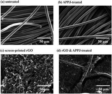 | ||
| Fig. 1 SEM micrographs of the (a) untreated, (b) APPJ-treated, (c) screen-printed rGO, and (d) rGO & APPJ-treated carbon cloths. | ||
Fig. 2(a) and (b) show the magnified images of the screen-printed rGO (Fig. 1(c)) and the rGO & APPJ-treated (Fig. 1(d)) carbon cloths, respectively. Fig. 2(a) reveals that the screen-printed rGO flakes merely adhere to the surface of the carbon fibers. However, Fig. 2(b) shows that the rGO flakes are sintered on the surface of the carbon fibers. Although some of the screen-printed rGOs were burned during the APPJ treatment, Fig. 2 demonstrates that the adhesion between rGO and the carbon cloth improved after the APPJ treatment.
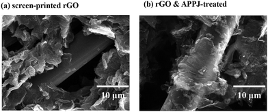 | ||
| Fig. 2 Magnified SEM images of the (a) screen-printed rGO and the (b) rGO & APPJ-treated carbon cloths. | ||
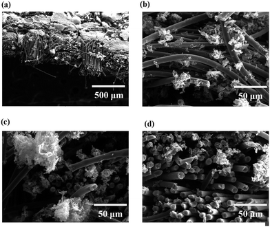
Fig. 3(a) shows the cross-sectional SEM image of the rGO & APPJ-treated carbon cloth. Fig. 3(b), (c) and (d) present the magnified SEM images of Fig. 3(a) at the surface, center, and bottom regions, respectively. Fig. 3 shows that most of the rGO flakes were deposited on the surface of the carbon cloth, as the rGO pastes were only screen-printed on one side of the carbon cloth. Nevertheless, as shown in Fig. 3(c) and (d), some rGO also percolated the center of the carbon cloth. This implies that the screen-printing of rGO not only provides contact areas on the surface of the carbon cloth, but also increases the surface area of the interior of the carbon cloth for the formation of biofilms.
Fig. 4 shows the results of water contact angle measurements of the untreated, APPJ-treated, screen-printed rGO, and rGO & APPJ-treated carbon cloths. As shown in Fig. 4, the untreated and screen-printed rGO carbon cloths exhibit high water contact angles of 127.9 ± 11.4° and 123.5 ± 11.8°, respectively. On the contrary, the water contact angles of both the APPJ-treated and the rGO & APPJ-treated carbon cloths were approximately zero, indicating that the surfaces of the APPJ-treated carbon cloths are extremely hydrophilic. The high hydrophilicity characteristic favors the biosorption of bacteria on the surface of electrodes.28
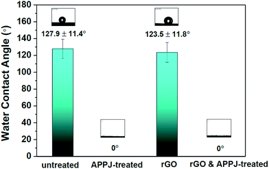 | ||
| Fig. 4 Water contact angles of the untreated, APPJ-treated, screen-printed rGO, and rGO & APPJ-treated carbon cloths. | ||
Fig. 5(a)–(d) show the C 1s XPS spectra results of the untreated, APPJ-treated, screen-printed rGO, and rGO & APPJ-treated carbon cloths, respectively. Fig. 5(a) reveals that the C 1s characteristic peak of the untreated carbon cloth can be deconvoluted into a major sp3 C–C peak (284.8 eV) and a minor C–O peak (286.1 eV). The origin of the C–O peak is attributed to the contamination on the surface of the carbon cloth. Fig. 5(b) demonstrates that, except of the C–C and C–O peaks, the APPJ-treated carbon cloth exhibited additional C![[double bond, length as m-dash]](https://www.rsc.org/images/entities/char_e001.gif) O (287.3 eV) and COOH peaks (288.7 eV). Fig. 5(c) shows that the screen-printed rGO carbon cloth comprises sp3 C–C, sp2 C–C, C–O, C
O (287.3 eV) and COOH peaks (288.7 eV). Fig. 5(c) shows that the screen-printed rGO carbon cloth comprises sp3 C–C, sp2 C–C, C–O, C![[double bond, length as m-dash]](https://www.rsc.org/images/entities/char_e001.gif) O, and COOH peaks at approximately 284.8, 284.4, 286.1, 287.3, and 288.7 eV, respectively. The significant sp2 C–C peak at approximately 284.4 eV is attributed to graphene in the screen-printed rGO. The significant C–O and C
O, and COOH peaks at approximately 284.8, 284.4, 286.1, 287.3, and 288.7 eV, respectively. The significant sp2 C–C peak at approximately 284.4 eV is attributed to graphene in the screen-printed rGO. The significant C–O and C![[double bond, length as m-dash]](https://www.rsc.org/images/entities/char_e001.gif) O peaks correspond to ethyl cellulose in the organic binder. The minor COOH peak is assigned to oxygen bonded to carbon at the edges of the rGO sheets.29–31Fig. 5(d) shows that the rGO & APPJ-treated carbon cloth also consists of sp3 C–C, sp2 C–C, C–O, C
O peaks correspond to ethyl cellulose in the organic binder. The minor COOH peak is assigned to oxygen bonded to carbon at the edges of the rGO sheets.29–31Fig. 5(d) shows that the rGO & APPJ-treated carbon cloth also consists of sp3 C–C, sp2 C–C, C–O, C![[double bond, length as m-dash]](https://www.rsc.org/images/entities/char_e001.gif) O, and COOH peaks at approximately 284.8, 284.4, 286.1, 287.3, and 288.7 eV, respectively. However, compared with those of the peaks in the screen-printed rGO carbon cloth, the intensities of the C–O and the sp3 C–C peaks in the rGO & APPJ-treated carbon cloth are significantly lower. Besides, it is clear from Fig. 5(d) that the intensity of the sp2 C–C peak is higher than that of the sp3 C–C peak. These results suggest that most of the organic binder in the rGO was burned out during the APPJ treatment. In addition, the carbonyl and the carboxyl functional groups observed on the surface of the rGO & APPJ-treated carbon cloth were introduced during the APPJ treatment.28
O, and COOH peaks at approximately 284.8, 284.4, 286.1, 287.3, and 288.7 eV, respectively. However, compared with those of the peaks in the screen-printed rGO carbon cloth, the intensities of the C–O and the sp3 C–C peaks in the rGO & APPJ-treated carbon cloth are significantly lower. Besides, it is clear from Fig. 5(d) that the intensity of the sp2 C–C peak is higher than that of the sp3 C–C peak. These results suggest that most of the organic binder in the rGO was burned out during the APPJ treatment. In addition, the carbonyl and the carboxyl functional groups observed on the surface of the rGO & APPJ-treated carbon cloth were introduced during the APPJ treatment.28
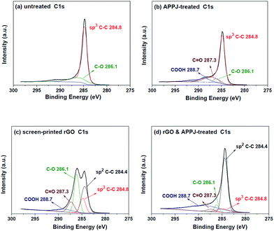 | ||
| Fig. 5 C 1s XPS spectra of the surfaces of (a) untreated, (b) APPJ-treated, (c) screen-printed rGO, and (d) rGO & APPJ-treated carbon cloths. | ||
Fig. 6(a)–(d) show the N 1s XPS spectra of the untreated, APPJ-treated, screen-printed rGO, and rGO & APPJ-treated carbon cloths, respectively. Fig. 6(a) shows that the characteristic N 1s peak was not observed on the surface of the untreated carbon cloth. Fig. 6(b) shows that APPJ-treated carbon cloth exhibits a significant N 1s peak, which can be deconvoluted into a major C–N peak (399.3 eV) and a minor NR4+ peak (401.3 eV), which were introduced during the N2-APPJ treatment. Fig. 6(c) shows that the screen-printed rGO carbon cloth also does not exhibit the characteristic N 1s peak. However, after the APPJ calcining, as shown in Fig. 6(d), the rGO & APPJ-treated carbon cloth showed the characteristic N 1s peak with a major C–N peak and a minor NR4+ peak. According to Fig. 5 and 6, we can conclude that the chemical bonding on the surface of the carbon cloth was effectively modified from major sp3 C–C and minor C–O to dominant sp2 C–C with abundant carbonyl, carboxyl, and ammonium functional groups after the rGO & APPJ treatment.
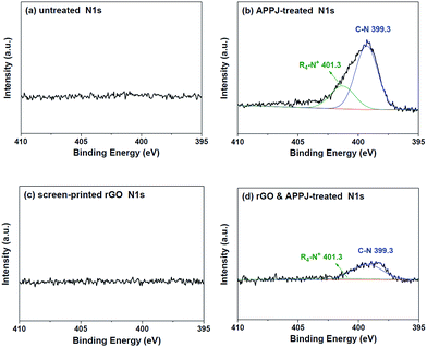 | ||
| Fig. 6 N 1s XPS spectra of the surfaces of (a) untreated, (b) APPJ-treated, (c) screen-printed rGO, and (d) rGO & APPJ-treated carbon cloths. | ||
Fig. 7(a)–(c) show the SEM images of the surfaces of the untreated, APPJ-treated, screen-printed rGO, and rGO & APPJ-treated carbon cloths, respectively, after immersing in the chamber of the MFC for 24 h. The SEM results of the screen-printed rGO carbon cloth are not shown herein, because the screen-printed rGO flakes peeled off from the surface of the carbon cloth after immersing in the chamber of the MFC. This is attributed to the poor adhesion between the screen-printed rGO and the carbon cloth before the APPJ calcining (Fig. 2(a)). Fig. 7(a) and (b) show that some microorganisms adhered on the surfaces of the untreated and the APPJ-treated carbon cloths. In addition, Fig. 7(b) shows that fragmentary biofilms formed between the APPJ-treated carbon fibers. Fig. 7(c) reveals that abundant microorganisms colonized on the surface of the rGO & APPJ-treated carbon cloth. Besides, the morphologies of rGO and the carbon fibers cannot be clearly identified in Fig. 7(c), implying that the surfaces of rGO and the carbon fibers are completely covered with the biofilm. Thus, we demonstrated that rGO & APPJ treatment can effectively facilitate the growth of microorganisms and the formation of biofilms on the surface of carbon cloth.
 | ||
| Fig. 7 SEM micrographs of the (a) untreated, (b) APPJ-treated, and (c) rGO & APPJ-treated carbon cloths after immersing in the chamber of the MFC for 24 h. | ||
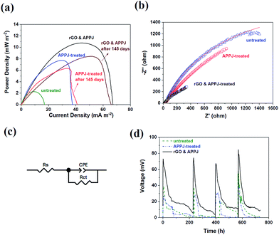
Fig. 8(a) shows the power density response curves of the MFCs configured with the untreated, APPJ-treated, and rGO & APPJ-treated carbon cloth electrodes. According to Fig. 8(a), the highest power densities of the MFCs configured with the untreated, APPJ-treated, and rGO & APPJ-treated carbon cloth electrodes were approximately 6.02 ± 0.01, 7.70 ± 0.15, and 10.80 ± 0.19 mW m−2, respectively. Fig. 8(a) also shows the power density response curves of the identical MFCs configured with the APPJ-treated and rGO & APPJ-treated carbon cloth electrodes measured after 145 days. The highest power densities of the MFCs configured with the APPJ-treated and rGO & APPJ-treated carbon cloth electrodes slightly decreased to approximately 6.24 ± 0.10 and 8.44 ± 0.06 mW m−2, respectively. This suggests that the MFCs configured with the APPJ-treated and rGO & APPJ-treated carbon cloth electrodes both exhibit good durability performance. Fig. 8(b) shows the results of the EIS measurements of the MFCs configured with the different electrodes. The figure shows a single capacitive loop, which could be fitted by the constant phase element (CPE) circuit model, in which the circuit comprises a CPE in parallel with a charge-transfer resistance (RCT), as demonstrated in Fig. 8(c). The impedance of the CPE can be calculated as ZCPE = 1/T(jω)φ.28,32 The Z-View® software was used in this study to fit the impedance of the CPE, in which φ is defined as CPE-P and T is defined as CPE-T. The RCT values of the untreated, APPJ-treated, and rGO & APPJ-treated carbon cloth electrodes are 5827.9, 5323.3, and 972.1 Ω, respectively, indicating that the rGO & APPJ treatment can effectively improve the charge transfer efficiency of the MFC. Fig. 8(d) shows the open-circuit voltage (OCV) results of the MFCs configured with the untreated, APPJ-treated, and rGO & APPJ-treated carbon cloth electrodes determined at an external resistance of 1000 Ω. Fig. 8(d) reveals that the MFC configured with the rGO & APPJ-treated carbon cloth electrode possessed a good durability performance for more than 700 h.
Discussion
In this study, we combined the advantages of screen-printing of rGO and APPJ treatment to enhance the power generation of MFCs. According to the electrochemical measurements shown in Fig. 8(a), the power density generated from the MFC is approximately 80% higher after the rGO & APPJ treatment. Further, the EIS results shown in Fig. 8(b) reveal that the total internal resistance of the MFC configured with the rGO & APPJ-treated carbon cloth electrode (972.1 Ω) is much lower than that of the unmodified MFC (5827.9 Ω). This implies that the efficiency of the transfer of electrons from bacteria to electrodes is improved by the rGO & APPJ treatment. The charge transfer resistance of the carbon cloth was reduced after rGO & APPJ treatment because of the combined efforts of good electrical conductivity and high surface area of the deposited rGO, improving the interfacial properties between the electrolyte and electrode and lowering the internal resistance and mass transfer losses.33–37 The improved electricity generation capability of the MFC configured with the rGO & APPJ-treated carbon cloth electrode can also be attributed to the increased surface area and the introduction of hydrophilic functional groups. As demonstrated in Fig. 1 to 3, the screen-printed rGO flakes significantly increase the surface area of the carbon cloth because of their high specific surface areas and porous structures. Moreover, the surface morphology of the screen-printed rGO changed from flake-like to sponge-like after the APPJ calcining, further increasing the surface area of rGO. The high surface area of the rGO & APPJ-treated carbon cloth electrode facilitates bacterial colonization and formation of biofilms, as demonstrated in Fig. 7, escalating the extracellular electron transfer efficiency and the power generation capability of the MFC. Further, according to the XPS results shown in Fig. 5 and 6, the chemical bonds on the surface of the rGO & APPJ-treated carbon cloth consisted of sp2 C–C, carbonyl, carboxyl, and ammonium functional groups. The higher intensity of the sp2 C–C peak implies that the rGO & APPJ surface modifications improved the electron transfer in the carbon cloth. The carbonyl, carboxyl, and ammonium functional groups contribute to the hydrophilic property of the rGO & APPJ-treated carbon cloth, as shown in Fig. 4, which promotes biocompatibility for the growth of microorganisms.38 Additionally, the carboxyl functional group promotes the transfer of electrons from the bacteria to the electrodes, because of the hydrogen bonding with the membrane-bound peptide bonds in bacterial cytochromes associated with the intracellular electron transfer chain.39 The positive charge of the ammonium functional groups also helps in the formation of biofilms and the adhesion of bacteria on the surface of the carbon cloth.40APPJ has been found to be highly reactive with carbonaceous materials.25,26,41–43 Reactive plasma species in nitrogen APPJ react vigorously with ethyl cellulose (EC) and rGOs. The reactivity is even higher with EC than with rGOs. In this reaction of nitrogen APPJ with rGO pastes that contain ECs, we can typically observe the reduction in C–O bonding contents that is contributed by ECs (as evidenced by XPS), in a shorter processing time. This reduction in C–O bonding content after nitrogen APPJ processing is also observed in this study (Fig. 5). C–C bonding content is mainly contributed by rGOs and carbon fibers of the carbon cloth. As the APPJ processing time is further increased, the rGOs are damaged and oxidized/evaporated.25,26 In this case, with rGOs on the carbon cloth, the C–C peak remains at a high level after APPJ processing because of the presence of carbon fibers (which are typically approximately 10 μm in diameter) on the carbon cloth. Using optical emission spectroscopy (OES) to control the processing time properly, we can burn ECs while retaining much of the rGOs.43 The optimal APPJ processing time is typically within 15 s. Furthermore, this APP process and screen-printing of rGO can be performed on substrates with various types of materials, including porous and solid ones. This provides high flexibility in material deposition and surface modification processes. This nitrogen APPJ processing of screen-printed rGO pastes is economically favorable in terms of the thermal budget in materials processing. In our previous paper,42 we estimated that this ultrashort APPJ processing time (11 s) can render an estimated energy consumption per unit area of 1.1 kJ cm−2, which is only one-third of that consumed in a conventional furnace calcination process. This is, therefore, a time- and energy-saving process beneficial for future mass production. Moreover, APPJ treatment can easily introduce abundant hydrophilic functional groups on the surface of the carbon cloth, which are formed from the nitrogen and oxygen atoms in the atmosphere instead of exogenous chemicals.28 This indicates that APPJ is an environmentally friendly process, which is important for the growth of microorganisms in MFCs. Compared with other graphene-based surface modification techniques, the screen-printing of rGO & APPJ treatment is time saving and cost effective, consumes low energy, and is suitable for large-area processing. Therefore, the screen printing of the rGO & APPJ treatment process is promising for the manufacture of large-scale MFC stacks for practical engineering applications.
Conclusions
This study investigated the surface and electrochemical properties of carbon cloth electrodes surface-modified by screen printing of rGO and APPJ treatment for applications in MFCs. The SEM results showed that the screen-printed rGO was deposited on the surface of the carbon cloth as well as percolated into the central region, providing more surface area for the adhesion of bacteria. The subsequent APPJ calcining not only burned the organic binder in the rGO paste, but also enhanced the adhesion between rGO and the carbon cloth. The wettability measurements revealed that the carbon cloth was highly hydrophilic after rGO & APPJ treatment. The XPS results showed the presence of abundant carbonyl, carboxyl, and ammonium hydrophilic functional groups on the surface of the rGO & APPJ-treated carbon cloth. These hydrophilic functional groups improve the biocompatibility, facilitate the transfer of electrons from the attached bacteria to the electrodes, and assist in the formation of biofilms on the surface of the carbon cloth. The electrochemical measurements demonstrated that the highest power density of the MFC significantly increased from 6.02 ± 0.01 to 10.80 ± 0.19 mW m−2 after the rGO & APPJ treatment. The EIS analysis showed that the total internal resistance of the MFC was significantly reduced after the rGO & APPJ treatment. The screen printing of rGO followed by the APPJ calcining is a clean, time-saving, and economical surface modification process. The possibility of easy large-area surface modification using both screen printing of rGO and APPJ calcining is ideal for the manufacture of large-scale MFC stacks with maximized power generation.Conflicts of interest
There are no conflicts to declare.Acknowledgements
The authors gratefully acknowledge the financial support provided by the Ministry of Science and Technology (MOST), Taiwan, under Grant No. MOST 104-2221-E-197-004-MY3 (S. H. Chang), 105-2221-E-002-047-MY3 (J. Z. Chen) and 106-2221-E-197-202-MY3 (B. Y. Chen).Notes and references
- B. Logan, B. Hamelers, R. Rozendal, U. Schröder, J. Keller, S. Freguia, P. Aelterman, W. Verstraete and K. Rabaey, Environ. Sci. Technol., 2006, 40, 5181–5192 CrossRef CAS PubMed.
- B. E. Logan and M. Elimelech, Nature, 2012, 488, 313–319 CrossRef CAS PubMed.
- B. E. Logan and K. Rabaey, Science, 2012, 337, 686–690 CrossRef CAS PubMed.
- C. Santoro, C. Arbizzani, B. Erable and I. Ieropoulos, J. Power Sources, 2017, 356, 225–244 CrossRef CAS PubMed.
- M. Zhou, M. Chi, J. Luo, H. He and T. Jin, J. Power Sources, 2011, 196, 4427–4435 CrossRef CAS.
- P. Y. You and S. K. Kamarudin, Chem. Eng. J., 2017, 309, 489–502 CrossRef CAS.
- Y. C. Yong, X. C. Dong, M. B. Chan-Park, H. Song and P. Chen, ACS Nano, 2012, 6, 2394–2400 CrossRef CAS PubMed.
- V. S. Sarathi and K. S. Nahm, Biosens. Bioelectron., 2013, 43, 461–475 CrossRef PubMed.
- Y. Wang, B. Li, D. Cui, X. Xiang and W. Li, Biosens. Bioelectron., 2014, 51, 349–355 CrossRef CAS PubMed.
- J. Liu, J. Liu, W. He, Y. Qu, N. Ren and Y. Feng, J. Power Sources, 2014, 265, 391–396 CrossRef CAS.
- W. Liu, S. Cheng and J. Guo, Appl. Surf. Sci., 2014, 320, 281–286 CrossRef CAS.
- H. F. Cui, L. Du, P. B. Guo, B. Zhu and J. H. Luong, J. Power Sources, 2015, 283, 46–53 CrossRef CAS.
- Y. Hindatu, M. S. M. Annuar and A. M. Gumel, Renewable Sustainable Energy Rev., 2017, 73, 236–248 CrossRef CAS.
- H. Yuan and Z. He, Nanoscale, 2015, 7, 7022–7029 RSC.
- F. Yu, C. Wang and J. Ma, Materials, 2016, 9, 807 CrossRef PubMed.
- G. Gnana kumar, C. Joseph Kirubaharan, S. Udhayakumar, K. Ramachandran, C. Karthikeyan, R. Renganathan and K. S. Nahm, ACS Sustainable Chem. Eng., 2014, 2, 2283–2290 CrossRef CAS.
- J. Ito, J. Nakamura and A. Natori, J. Appl. Phys., 2008, 103, 113712 CrossRef.
- A. Das, S. Pisana, B. Chakraborty, S. Piscanec, S. Saha, U. Waghmare, K. S. Novoselov, H. R. Krishnamurthy, A. K. Geim, A. C. Ferrari and A. K. Sood, Nat. Nanotechnol., 2008, 3, 210–215 CrossRef CAS PubMed.
- S. Stankovich, D. A. Dikin, G. H. B. Dommett, K. M. Kohlhaas, E. J. Zimney, E. A. Stach, R. D. Piner, S. T. Nguyen and R. S. Ruoff, Nature, 2006, 442, 282–286 CrossRef CAS PubMed.
- J. X. Hou, Z. L. Liu and P. Y. Zhang, J. Power Sources, 2013, 224, 139–144 CrossRef CAS.
- H. Wang, G. Wang, Y. Ling, F. Qian, Y. Song, X. Lu, S. Chen, Y. Tong and Y. Li, Nanoscale, 2013, 5, 10283–10290 RSC.
- H. T. Chou, H. J. Lee, C. Y. Lee, N. H. Tai and H. Y. Chang, Bioresour. Technol., 2014, 169, 532–536 CrossRef CAS PubMed.
- A. Mehdinia, E. Ziaei and A. Jabbari, Int. J. Hydrogen Energy, 2014, 39, 10724–10730 CrossRef CAS.
- N. Garino, A. Sacco, M. Castellino, J. A. Muñoz-Tabares, A. Chiodoni, V. Agostino, V. Margaria, M. Gerosa, G. Massaglia and M. Quaglio, ACS Appl. Mater. Interfaces, 2016, 8, 4633–4643 CAS.
- T. H. Wan, Y. F. Chiu, C. W. Chen, C. C. Hsu, I. C. Cheng and J. Z. Chen, Coatings, 2016, 6, 44 CrossRef.
- F. H. Kuok, C. Y. Liao, T. H. Wan, P. W. Yeh, I. C. Cheng and J. Z. Chen, J. Alloys Compd., 2017, 692, 558–562 CrossRef CAS.
- C. H. Yang, F. H. Kuok, C. Y. Liao, T. H. Wan, C. W. Chen, C. C. Hsu, I. C. Cheng and J. Z. Chen, Mater. Res. Express, 2017, 4, 025504 CrossRef.
- S. H. Chang, J. S. Liou, J. L. Liu, Y. F. Chiu, C. H. Xu, B. Y. Chen and J. Z. Chen, J. Power Sources, 2016, 336, 99–106 CrossRef CAS.
- A. Lerf, H. He, M. Forster and J. Klinowski, J. Phys. Chem. B, 1998, 102, 4477–4482 CrossRef CAS.
- C. Mattevi, G. Eda, S. Agnoli, S. Miller, K. A. Mkhoyan, O. Celik, D. Mastrogiovanni, G. Granozzi, E. Garfunkel and M. Chhowalla, Adv. Funct. Mater., 2009, 19, 2577–2583 CrossRef CAS.
- W. Cai, R. D. Piner, F. J. Stadermann, S. Park, M. A. Shaibat, Y. Ishii, D. Yang, A. Velamakanni, S. J. An, M. Stoller, J. An, D. Chen and R. S. Ruoff, Science, 2008, 321, 1815–1817 CrossRef CAS PubMed.
- J. B. Jorcin, M. E. Orazem, N. Pebere and B. Tribollet, Electrochim. Acta, 2006, 51, 1473–1479 CrossRef CAS.
- G. Gnana kumar, C. Joseph Kirubaharan, S. Udhayakumar, C. Karthikeyan and K. S. Nahm, Ind. Eng. Chem. Res., 2014, 53, 16883–16893 CrossRef CAS.
- G. Gnana kumar, Z. Awan, K. S. Nahm and J. S. Xavier, Biosens. Bioelectron., 2014, 53, 528–534 CrossRef CAS PubMed.
- G. Gnana kumar, S. Hashmi, C. Karthikeyan, A. GhavamiNejad, M. Vatankhah-Varnoosfaderani and F. J. Stadler, Macromol. Rapid Commun., 2014, 35, 1861–1865 Search PubMed.
- M. V. Kannan and G. Gnana kumar, Biosens. Bioelectron., 2016, 77, 1208–1220 CrossRef CAS PubMed.
- C. Joseph Kirubaharan, K. Santhakumar, G. Gnana kumar, N. Senthilkumar and J. H. Jang, Int. J. Hydrogen Energy, 2015, 40, 13061–13070 CrossRef.
- T. H. Han, S. Y. Sawant, S. J. Hwang and M. H. Cho, RSC Adv., 2016, 6, 25799–25807 RSC.
- X. Tang, K. Guo, H. Li, Z. Du and J. Tian, Bioresour. Technol., 2011, 102, 3558–3560 CrossRef CAS PubMed.
- S. A. Cheng and B. E. Logan, Electrochem. Commun., 2007, 9, 492–496 CrossRef.
- T. H. Wan, C. C. Lee, C. W. Chen, C. C. Hsu, I. C. Cheng and J. Z. Chen, J. Electrochem. Soc., 2017, 164, H931–H935 CrossRef CAS.
- H. W. Liu, S. P. Liang, T. J. Wu, H. Chang, P. K. Kao, C. C. Hsu, J. Z. Chen, P. T. Chou and I. C. Cheng, ACS Appl. Mater. Interfaces, 2014, 6, 15105–15112 CAS.
- J. Z. Chen, C. C. Hsu, C. Wang, W. Y. Liao, C. H. Wu, T. J. Wu, H. W. Liu, H. Chang, S. T. Lien, H. C. Li, C. M. Hsu, P. K. Kao, Y. J. Yang and I. C. Cheng, Coatings, 2015, 5, 26–38 CrossRef CAS.
| This journal is © The Royal Society of Chemistry 2017 |

