
 Open Access Article
 This Open Access Article is licensed under a Creative Commons Attribution-Non Commercial 3.0 Unported Licence
Low-crystalline mesoporous CoFe2O4/C composite with oxygen vacancies for high energy density asymmetric supercapacitors†
Yan Zhao‡
a,
Yuanguo Xu‡ a,
Jie Zengb,
Biao Kong‡*b,
Xiwen Gengc,
Dongwei Lic,
Xiang Gaoc,
Kang Liangd,
Le Xu‡a,
Jiabiao Lian‡a,
Shuquan Huang‡a,
Jingxia Qiu‡a,
Yunpeng Huang‡a and
Huaming Li‡*a
a,
Jie Zengb,
Biao Kong‡*b,
Xiwen Gengc,
Dongwei Lic,
Xiang Gaoc,
Kang Liangd,
Le Xu‡a,
Jiabiao Lian‡a,
Shuquan Huang‡a,
Jingxia Qiu‡a,
Yunpeng Huang‡a and
Huaming Li‡*a
aInstitute for Energy Research, Jiangsu University, Zhenjiang 212013, PR China. E-mail: lhm@ujs.edu.cn
bDepartment of Chemistry, Shanghai Key Lab of Molecular Catalysisand Innovative Materials, iChEM, Fudan University, Shanghai 200433, PR China. E-mail: bkong@fudan.edu.cn
cNational Supercomputer Research Center of Advanced Materials, Advanced Materials Institute, Shandong Academy of Sciences, Jinan 250014, P. R. China
dSchool of Chemical Engineering, The University of New South Wales, Sydney, NSW 2052, Australia
First published on 7th December 2017
Abstract
Recently, nano/micro-scale Fe-based ferrites with high electrochemical performances have attracted extensive attention. However, almost all the mixed Fe-based oxide research paid close attention to the crystalline phase, despite the low-crystalline or amorphous phase possessing excellent electrochemical performance. Herein, a low-crystalline mesoporous cobalt ferrite and carbon composite (L-CoFe2O4/C) material with high surface area and superior electrical conductivity was prepared via a simple citric acid assisted sol–gel approach and calcination process. The L-CoFe2O4/C electrode exhibits an unprecedented specific capacitance (600 F g−1 at 1 A g−1), which precedes some of the reported mixed Fe-based ferrite electrodes and their crystalline counterparts. The excellent electrochemical performance can mainly be attributed to the sufficient diffusion and reaction of electrolyte ions, more surface defects (e.g. oxygen vacancies) for redox reactions, and the predominant electro-conductivity of the composite during the charging/discharging process. Moreover, an L-CoFe2O4/C-based asymmetric supercapacitor exhibited high energy density and power density, and outperformed most of the reported mixed Fe-based symmetric and asymmetric supercapacitors. These findings promote new opportunities for low-crystalline Fe-based metal oxides as high performance energy storage devices.
Introduction
Owing to the increasing and urgent concern about environmental pollution and the rapidly growing demand for clean energy generation and storage, advanced energy storage devices such as supercapacitors and rechargeable batteries have received much attention in recent years.1–5 Because of the high power density, fast charging–discharging rate and excellent cycling stability, supercapacitors have drawn great research recognition as one of the most favorable candidates for the next generation of energy storage devices, such as portable electronics, medical devices and other back-up power devices.6,7 However, the low energy density of supercapacitors greatly hinders their further practical applications. Therefore, there is an urgent need to explore high performance supercapacitors with high power and energy density.7,8 According to the energy calculation formula E = 1/2CV2, the energy density of supercapacitors can be improved by increasing the capacitance (C) of the electrode material, the operation voltage window (V), or both.9 Thus, the physical and chemical properties of electrode materials are of great importance. Moreover, the incorporation of carbon materials not only facilitates the enhancement of the specific capacitance of the composites, but also results in a higher electrical conductivity and better structural mechanical stability than those of the monomers.10 When combined with carbon-based electrodes to construct asymmetric supercapacitors, the operation voltage window of supercapacitors can be further enlarged.11,12Among various pseudocapacitor electrode materials, spinel ferrites have attracted great interest due to their remarkable catalytic, magnetic, optical, and electrical properties.13–15 Recently, MnFe2O4,16,17 NiFe2O4 (ref. 18 and 19) and ZnFe2O4 (ref. 20–23) have been reported as excellent supercapacitor electrodes. Additionally, cobalt spinel ferrite (CoFe2O4) with a high theoretical capacity (916 mA h g−1) has been regarded as a good choice for anode materials because of the synergic effect between Co and Fe.25,26 It may be feasible to tune the energy density and working voltage of CoFe2O4 with Co and Fe by varying the metal content. The conductivity of CoFe2O4 is also better than that of the single components.27–29 Recently, Sankar et al. fabricated CoFe2O4 porous particles for supercapacitor electrodes with a specific capacitance of 125 F g−1 at 0.5 A g−1.30 The CoFe2O4//rGO hybrid supercapacitor presented a low energy density of 12.14 W h kg−1 at 3 mA. Lokhande et al. prepared CoFe2O4 nanoflakes using a low cost chemical bath deposition (CBD) method.31 However, the maximum specific capacitance was only 366 F g−1 at 5 mV s−1. Although Wang et al. successfully prepared high-performance cobalt ferrite/graphene/polyaniline nanocomposites (767.7 F g−1 at 0.1 A g−1) via a hydrothermal method and in situ polymerization process, the specific capacitance of the composite at a high current density was still very low (329.8 F g−1 at 3 A g−1).25 The reported CoFe2O4 nanostructures for the pseudocapacitors presented unsatisfactory electrical properties, probably due to the intrinsic low electrical conductivity, severe aggregation of the nanoparticles and large volume variation during the charging/discharging process.24–26,30,31 Therefore, the electrochemical properties of CoFe2O4 nanostructures should be enhanced and the complex fabrication strategies should be simplified.26 What’s more, the reported energy densities still need further improvement.
To solve the aforementioned issues, two strategies can be utilized: firstly, the particle size can be decreased to nanometer size, or nanocomposites with sufficient space and higher electrical properties to buffer the volume change and enhance the conductivity can be designed and fabricated;32 secondly, the mass balance between the positive and negative material can be optimized, which is crucial to the modification of the final energy density.33
Herein, we report a mesoporous low-crystalline cobalt ferrite oxide combined with carbon (L-CoFe2O4/C) as an asymmetric supercapacitor electrode material, synthesized via a citric acid assisted sol–gel method and heat treatment process. The high surface area of the mesoporous L-CoFe2O4/C can provide additional pores and spaces for an electrolyte to diffuse with low transfer limitation. The introduction of carbon in the composite material facilitates electron transfer within the framework, which can significantly improve the electrode material’s conductivity. The detected oxygen vacancies and the low crystalline nature in the electrode material were found to improve the wettability and expose more active sites which are accessible for the electrolyte on the surface, which allows the reversible redox reaction to take place at the interface of the electrode material and the electrolyte. The obtained L-CoFe2O4/C supercapacitor electrode material displayed excellent specific capacitances, great structural stability and good cycling stability, which exceed those of some of the previously reported complex Fe-based electrodes as well as their crystalline counterparts. Additionally, the L-CoFe2O4/C-based asymmetric supercapacitor exhibited a higher electrochemical performance than that of the majority of mixed Fe-based asymmetric and symmetric supercapacitor devices reported in the literature. This work could pave a new way for the fabrication of advanced low-crystalline Fe-based electrode materials for high performance supercapacitors.
Experimental
Preparation of the CoFe-precursor, CoFe2O4 and the L-CoFe2O4/C composite
CoFe2O4 and the L-CoFe2O4/C composite were prepared via a citric acid assisted sol–gel method and a subsequent calcination process. Typically, 10 mmol ferric nitrate was firstly dissolved in 50 mL distilled water. Then, 5 mmol cobalt nitrate powder was slowly added into the solution with vigorous magnetic stirring for another 30 min. After that, 0.30 mol L−1 citric acid (50 mL) solution was dropped into the former solution under magnetic stirring. The mixed solution was reacted at 60 °C for 1 h and then heated at 90 °C for 1 day. The resulting powder was collected and labeled as CoFe-precursor. Finally, the powder was annealed at 300 °C, 400 °C and 700 °C for 4 h in air with a heating rate of 10 °C min−1, and labeled as L-CoFe2O4/C, CoFe2O4-400, and CoFe2O4-700, respectively.Preparation of the positive and negative electrodes
Four CoFe-based electrodes and an activated carbon (AC) electrode were fabricated by pasting a homogeneous slurry of the active material (L-CoFe2O4/C, CoFe2O4-400, CoFe2O4-700, CoFe-precursor or AC), carbon black and poly(tetrafluoroethylene) with a mass ratio of 72![[thin space (1/6-em)]](https://www.rsc.org/images/entities/char_2009.gif) :23:5 into a porous nickel foam current collector (1 × 4 cm2). The as-obtained electrodes were further dried at 140 °C for 3 h to completely evaporate the solvent. After drying, the nickel foam coated with the active material was pressed at 10 MPa to obtain the final electrode.
:23:5 into a porous nickel foam current collector (1 × 4 cm2). The as-obtained electrodes were further dried at 140 °C for 3 h to completely evaporate the solvent. After drying, the nickel foam coated with the active material was pressed at 10 MPa to obtain the final electrode.
Assembly of the L-CoFe2O4/C//AC asymmetric supercapacitor
The prepared AC electrode and the L-CoFe2O4/C electrode were directly used as negative and positive electrodes. 2 M KOH solution was used as an electrolyte. A full cell was assembled with the above mentioned two electrodes, and one piece of porous polymer membrane was used as the separator.Characterization
The X-ray diffraction (XRD) patterns of the samples which were thoroughly ground in a mortar were collected using a Bruker D8 diffractometer with Cu-Kα radiation, λ = 1.5418 Å. The morphology and microstructure of the samples were investigated using scanning electron microscopy (SEM Hitachi, Japan, 30 kV) and transmission electron microscopy (TEM Hitachi H-800, Hitachi Corp). HRTEM images were recorded on a TSL, AMETEK high-resolution transmission electron microscope. The vibrational properties were characterized by Raman scattering (T6400, excitation-beam wavelength: 514.5 nm). X-ray photoelectron spectroscopy (XPS) was carried out on a Kratos AXIS Ultra DLD. The thermal stability of the samples was measured by thermal gravimetric analysis (TGA) under flowing air at a heating rate of 10 K min−1 on the TA Instrument SDT Q600. A Quantachrome Autosorb 6B system was used to characterize the specific surface areas and pore structures of the electrode materials. The Brunauer–Emmett–Teller (BET) method was utilized to calculate the specific surface area of each sample.Electrochemical measurements
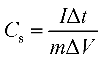
Electrochemical tests were conducted with 2 M KOH aqueous solution as the electrolyte at ambient temperature. The electrodes were measured in a three-electrode electrochemical cell, where the as-synthesized material was used as the working electrode, and the reference electrode and the counter electrode were a Hg/HgO electrode and a platinum plate, respectively. The specific capacitances of the asymmetric supercapacitor were measured in a two-electrode system. Cyclic voltammetry (CV) and galvanostatic charge–discharge (GCD) measurements were performed on a CHI-660E electrochemical workstation at room temperature. The electrochemical impedance spectrum (EIS) of the material was obtained in the frequency range of 100 kHz to 0.01 Hz with an AC potential amplitude of 5 mV and zero DC voltage. The specific capacitances (Cs) of the electrodes can be calculated using eqn (1):34,35
 | (1) |
 | (2) |
 | (3) |
 | (4) |
Results and discussion
As shown in Scheme 1, the formation mechanism of the mesoporous CoFe2O4 and L-CoFe2O4/C composite samples can be illustrated as follows: firstly, the salts of cobalt ions and iron ions were mixed together to form a uniform solution. Then, citric acid was used as a chelating agent to coordinate to the metal ions and enhance the speed of the chemical reaction. It is worth mentioning that the presence of citric acid in the reaction plays a crucial role in the formation of the CoFe-precursor.38 The citric acid produces abundant carboxyl groups in the hydrolyzation process, in a role that is similar to that of trisodium citrate dehydrate.39–41 After that, a gel of the CoFe-precursor was obtained by evaporation of water, and the complex of ferric citrate and cobalt citrate as the main carbon resources is obtained. When annealed at low temperature, the CoFe-precursor decomposed into carbon dioxide and water with a large amount of carbon left due to the fractionated pyrolysis and oxidation of the 3D CoFe-precursor at a high heating rate of 10 °C min−1 in a limited reaction time, which produced the mesoporous structure and the carbon framework. At the same time, defects, such as oxygen vacancies, can be generated in the inverse spinel structure of CoFe2O4. It is noted that if the precursor is heated at a high temperature, the remaining carboxyl groups are directly converted into carbon dioxide. Therefore, the porous carbon framework is destroyed. This deduction can be verified from the TG and DSC analysis in Fig. S1.† The analysis was conducted in a temperature range from 40 °C to 800 °C at an annealing rate of 10 °C min−1. Two obvious weight losses occurred in the temperature ranges of 100 °C to 200 °C and 270 °C to 360 °C, corresponding to the loss of free water and crystalline water, and the decomposition of the metal complex, respectively. The fastest weight loss rate was seen at 320.9 °C, which indicates the presence of residual carbon at 300 °C. Almost no weight loss was detected above 360 °C, indicating the complete formation of high crystalline CoFe2O4.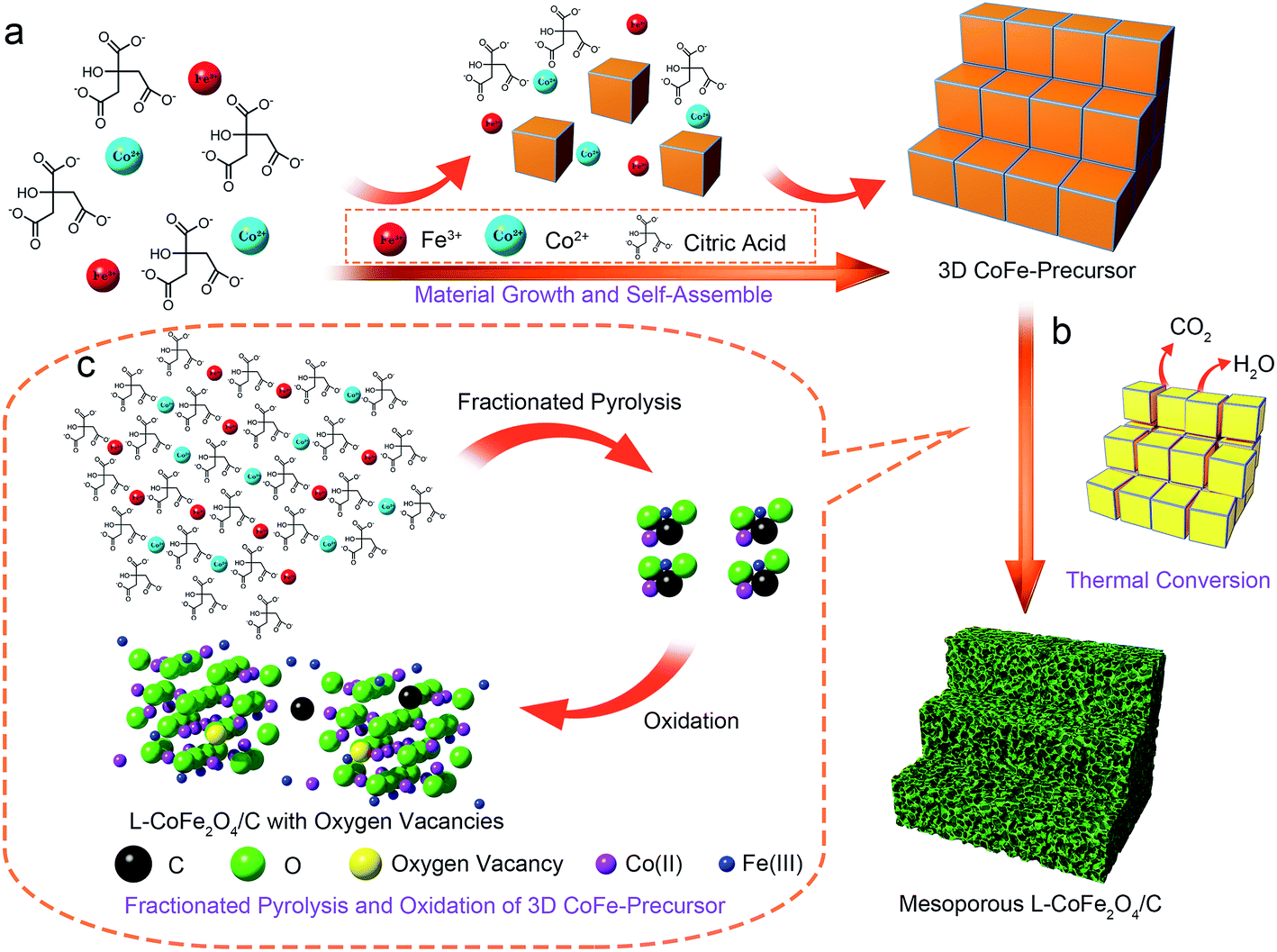 | ||
| Scheme 1 A schematic illustration of the procedures for constructing the mesoporous L-CoFe2O4/C composite nanostructures. | ||
The SEM images of the CoFe-precursor, L-CoFe2O4/C, CoFe2O4-400 and CoFe2O4-700 samples are shown in Fig. S2.† It can be demonstrated that the as-synthesized samples are composed of a large number of irregular blocks with sizes ranging from tens of nanometers to tens of micrometers. The surface of the CoFe-precursor was very smooth, which is different from L-CoFe2O4/C and CoFe2O4-based oxides. As the annealing temperature rises, the size of the CoFe2O4-based materials became smaller and more uniform. This may be attributed to the enlarged average pore diameters and the decreased specific surface area and pore volume of the samples, which is verified by the BET result described later.
The surface areas, pore volumes and average pore sizes of the samples were investigated using the nitrogen adsorption/desorption technique (Fig. S3†). The data are summarized in Table 1. The sample of L-CoFe2O4/C exhibited a type IV isotherm with an obvious hysteresis loop as shown in Fig. S3a,† confirming the formation of the open pores, generated from the decomposition of the trapped cobalt ferrite precursor and the removal of water. However, almost no open pores were detected in the samples of CoFe-precursor and CoFe2O4-700, indicating the low surface areas of the two samples. The average pore diameters of the CoFe-precursor, L-CoFe2O4/C, CoFe2O4-400 and CoFe2O4-700 from the Barrett–Joyner–Halenda (BJH) plot (Fig. S3b†) were calculated to be 3.06, 5.43, 9.77 and 17.4 nm, respectively, which classified the materials as mesoporous structures. Interestingly, the BET specific surface area and pore volume of L-CoFe2O4/C were observed to be 131 m2 g−1 and 0.196 cm3 g−1, respectively, which were significantly higher than the values obtained for the CoFe-precursor (9.12 m2 g−1 and 0.007 cm3 g−1), CoFe2O4-400 (63.8 m2 g−1 and 0.154 cm3 g−1) and CoFe2O4-700 (3.46 m2 g−1 and 0.012 cm3 g−1). These results may be ascribed to the higher degree of crystallinity during the temperature rise, which significantly enhances the pore sizes at the cost of decreasing the surface area and pore volume.42,43 The quite large surface area, high pore volume and the mesopores of the L-CoFe2O4/C sample could be favorable for improving the electrochemical performance by reducing the ion transport limitation in electrodes.44
| Materials | Surface area (cm2 g−1) | BJH average pore size (nm) | Pore volume (cm3 g−1) |
|---|---|---|---|
| L-CoFe2O4/C | 131 | 5.43 | 0.196 |
| CoFe2O4-400 | 63.8 | 9.77 | 0.154 |
| CoFe2O4-700 | 3.46 | 17.4 | 0.012 |
| CoFe-precursor | 9.12 | 3.06 | 0.007 |
Fig. 1a clearly displays a typical TEM image of the porous structure of the L-CoFe2O4/C blocks which could be suitable for the in-depth diffusion of the electrolyte. High-resolution transmission electron microscopy (HRTEM) images of L-CoFe2O4/C are shown in Fig. 1b and c, revealing the presence of CoFe2O4 and carbon. Moreover, the composite has a fringe spacing of 0.25 nm, corresponding to the (311) plane of the spinel cubic CoFe2O4. The selected area electron diffraction (SAED) pattern of L-CoFe2O4/C also reflects the crystallinity with ring planes corresponding to the (311), (222), (400), (422), (440), and (533) planes of the spinel system (Fig. 1d). Energy dispersive X-ray spectroscopy confirmed the presence of Co, Fe, C and O. The atomic ratio of Co:Fe:O:C is 4.37:7.18:29.26:59.18, which is consistent with the XRD result. The elemental mapping analysis of a typical mesoporous L-CoFe2O4/C composite also clearly revealed the elemental distributions of Fe, Co, C, and O (Fig. 1f–i). The tightly connected carbon around CoFe2O4 can not only be regarded as the framework of the composite, but also to facilitate the electron transport and finally enhance the electrical conductivity.
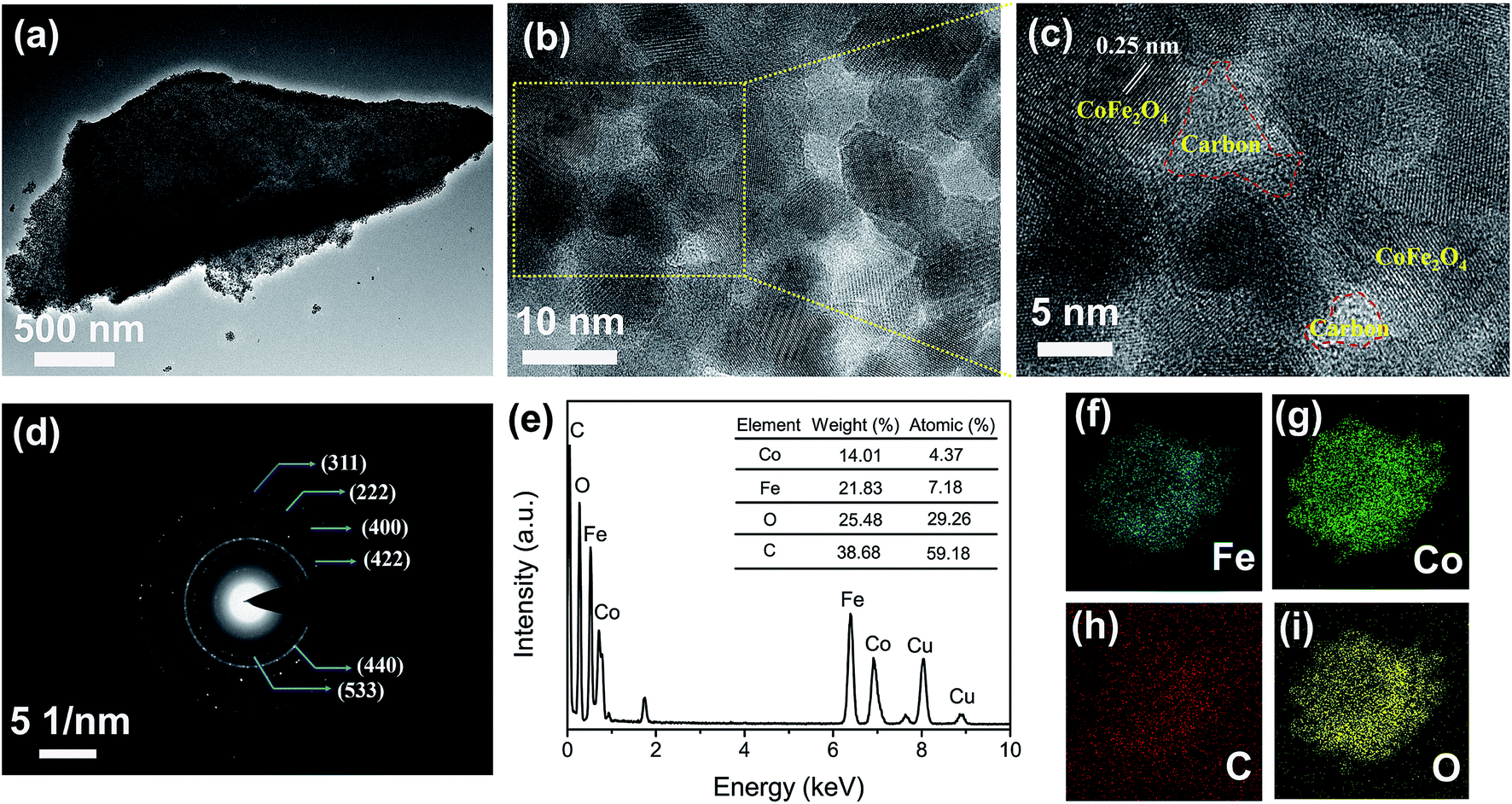 | ||
| Fig. 1 (a) The typical TEM image of the mesoporous L-CoFe2O4/C composite. (b) An HRTEM image and (c) an enlarged HRTEM image of the mesoporous L-CoFe2O4/C composite. (d) The SAED pattern and (e) EDX data of the mesoporous L-CoFe2O4/C composite. (f–i) Elemental mappings of a typical mesoporous L-CoFe2O4/C composite, revealing the elemental distributions of Fe, Co, C, and O. | ||
Fig. 2a shows the XRD patterns of the as-prepared nanostructures annealed at various temperatures. The sample without heat treatment shows no peak at the diffraction angles ranging from 10° to 80°, proving the amorphous nature of the CoFe-precursor. The as-prepared sample annealed at low temperature only exhibits four humps at 35.7°, 43.4°, 57.1° and 62.7°, indicating that the sample of L-CoFe2O4/C generally has low crystallinity.45 The broad peaks of L-CoFe2O4/C indicate the small size of the particles, which is consistent with the calculated results by the Brunauer–Emmett–Teller (BET) methods. As the annealing temperature increases, these peaks become narrower and sharper. The diffraction peaks of the CoFe2O4-400 and CoFe2O4-700 samples at 18.4° (111), 30.2° (220), 35.6° (311), 37.3° (222), 43.2° (400), 53.7° (422), 57.1° (511), 62.7° (440), 71.2° (620), 74.2° (533), 75.2° (622) and 79.2° (444) can be attributed to the spinel cubic structure of CoFe2O4 (JCPDS no. 22-1086). The Raman spectrum of the spinel L-CoFe2O4/C blocks is shown in Fig. S4.† Four Raman active modes (T12g, Eg, T32g, and A1g) can be detected, which are different from those of the CoFe-precursor and attributed to the existence of CoFe2O4.
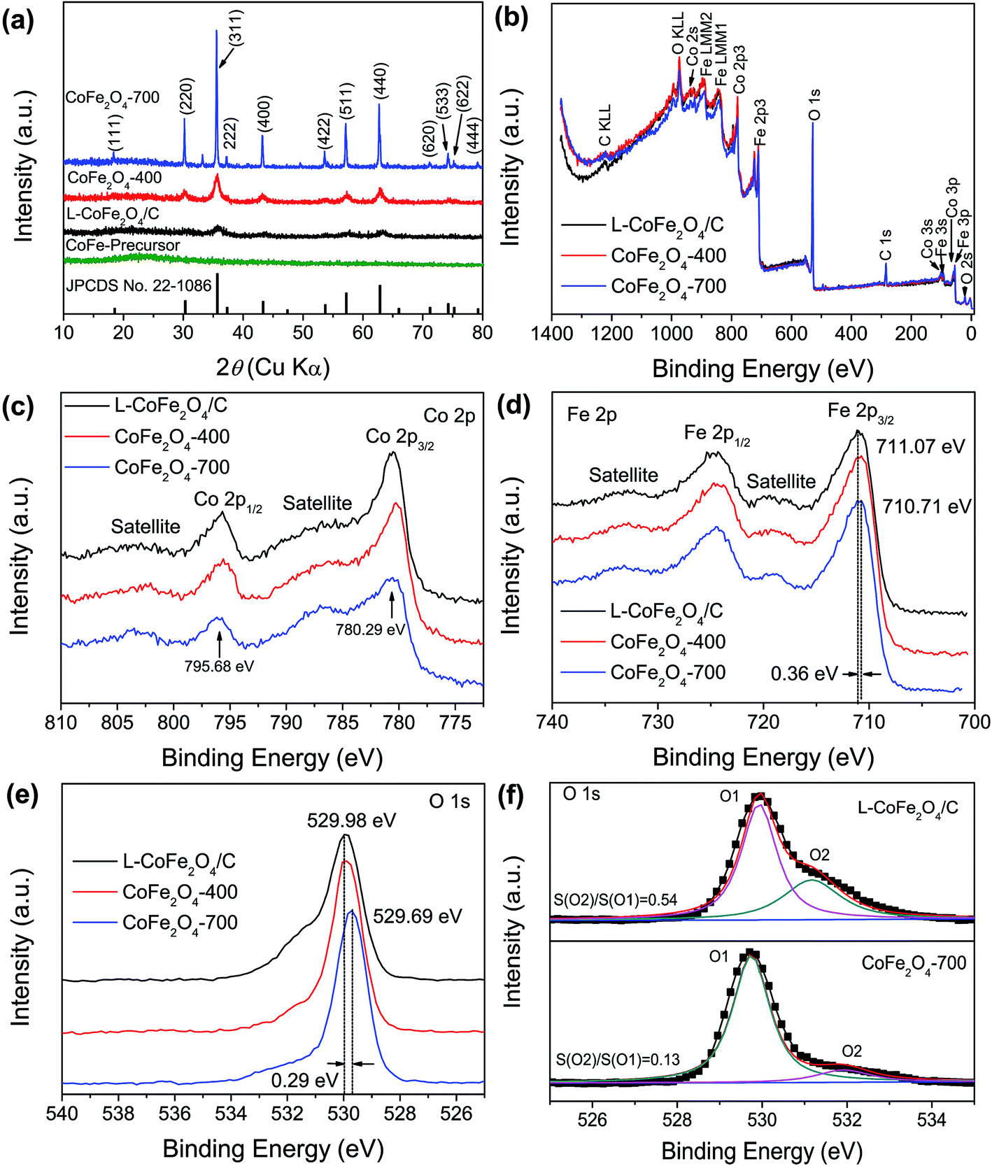 | ||
| Fig. 2 (a) XRD patterns of the as-prepared mesoporous L-CoFe2O4/C composite, CoFe2O4-400 and CoFe2O4-700 samples. (b) The full XPS spectra, and high resolution (c) Co 2p, (d) Fe 2p and (e) O 1s XPS spectra of the mesoporous L-CoFe2O4/C composite, CoFe2O4-400 and CoFe2O4-700. (f) The Gaussian fitting high resolution O 1s XPS spectra of the L-CoFe2O4/C composite and CoFe2O4-700. | ||
XPS was performed to investigate the change of surface bonding energy, as well as the electronic valence band position of the samples. Fig. 2b shows a full-survey-scan spectrum of the samples. Co, O, and Fe can be obviously identified with the binding energies of Co 2p, O 1s, and Fe 2p electrons, revealing the presence of CoFe2O4 samples (Fig. 2c–e). Fig. 2c shows the normalized Co 2p core level XPS spectra of the L-CoFe2O4/C, CoFe2O4-400 and CoFe2O4-700 samples. The two strong peaks centered at binding energies of 795.68 and 780.29 eV are consistent with the typical values for CoFe2O4.46,47 These indicate the presence of Co2+ in the sample.48 The Fe 2p core level XPS spectra of the samples are shown in Fig. 2d, and exhibit two characteristic peaks at about 724 and 711 eV, corresponding to the Fe 2p1/2 and Fe 2p3/2 spin–orbit peaks of CoFe2O4, respectively, revealing a valence state of Fe3+ in the samples. It is worth noticing that the Fe 2p3/2 binding energy for L-CoFe2O4/C is negatively shifted by 0.36 eV (711.1 eV) as compared to the Fe 2p3/2 peak (710.7 eV) of CoFe2O4-700, which implies that the Fe3+ species exist in more than one coordination environment. Clearly, the negative shift of binding energies can be ascribed to the strong interaction between the host CoFe2O4 and carbon.49 Meanwhile, the O 1s XPS signal in Fig. 2e reveals the different coordination environment of the O 1s species. The main peak (O1) at around 530 eV and the other weak peak (O2) at about 532 eV are attributed to the typical metal–oxygen bonds and the defects with low oxygen, respectively (Fig. 2f). Moreover, the two fitting peaks of L-CoFe2O4/C and CoFe2O4-700 indicate that both of them can be resolved into two Gaussian peaks. The high peak area ratio for L-CoFe2O4/C indicates a larger amount of defects such as oxygen vacancies at the surface, which can significantly improve the conductivity and accelerate the kinetics of surface redox reactions, and thus will enhance the energy storage performance.13,49
With the advantages of the internal mesoporous structure and low crystalline nature of L-CoFe2O4/C, the as-obtained L-CoFe2O4/C sample can be used as an electrode material for supercapacitors to provide remarkable energy storage properties. Fig. 3a shows the CV curves of the L-CoFe2O4/C electrode at different scan rates in the potential range of 0 to 0.5 V. The CV curves with a couple of redox peaks imply that the capacitance characteristics are mainly controlled by faradaic reactions.50,51 Even at higher scan rates, the CV curves retained a typical pseudocapacitive behavior, indicating an excellent electrochemical performance. The redox process may be:
| CoFe2O4 + H2O + OH− ↔ CoOOH + 2FeOOH + e− | (5) |
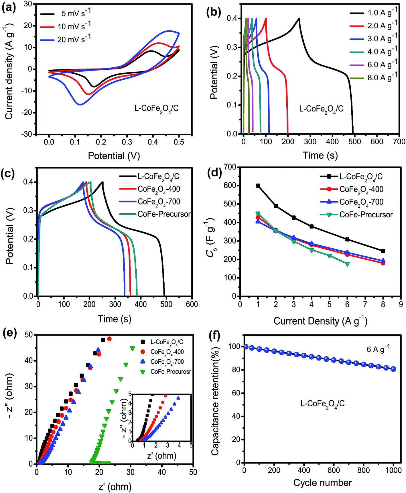 | ||
| Fig. 3 (a) The CV curves of the mesoporous L-CoFe2O4/C composite electrode at different scan rates. The GCD curves of (b) the mesoporous L-CoFe2O4/C composite electrode at various current densities and (c) a comparison of the mesoporous L-CoFe2O4/C composite, CoFe2O4-400, CoFe2O4-700 and CoFe-precursor electrodes at a current density of 1 A g−1. (d) The specific capacitance of the mesoporous L-CoFe2O4/C composite, CoFe2O4-400, CoFe2O4-700 and CoFe-precursor electrodes at different current densities. (e) A comparison of the Nyquist plots of the mesoporous L-CoFe2O4/C composite, CoFe2O4-400, CoFe2O4-700 and CoFe-precursor electrodes at an initial potential of 0 V, and the enlarged EIS at the high frequency region (inset). (f) The cycling performance of the mesoporous L-CoFe2O4/C composite electrode at a current density of 6 A g−1. | ||
Moreover, the pair of redox peaks is nearly symmetrical, revealing great reversibility of the redox reactions in the electrode. The current density increased along with the increase of scan rate with a minor shape change, indicating good kinetic reversibility.52 The redox peaks of the bare Ni foam (Fig. S5†) were observed, but the small specific capacitance suggests a negligible contribution of Ni foam to the overall capacitance.
As shown in Fig. 3b, the galvanostatic charge–discharge (GCD) measurements of the L-CoFe2O4/C electrode were obtained at various current densities, and they further demonstrate the pseudocapacitor nature of the material. Fig. 3c presents the GCD curves of the L-CoFe2O4/C, CoFe2O4-400, CoFe2O4-700 and CoFe-precursor electrodes at a current density of 1 A g−1. It can be seen that the discharging time of the L-CoFe2O4/C electrode is much longer than that of the CoFe2O4-400, CoFe2O4-700 and CoFe-precursor electrodes, signifying a relatively higher specific capacitance. This might be due to the relatively high surface area of the L-CoFe2O4/C electrode material, which could facilitate the electron transfer between the electrolyte and electrode and the super wettability of the electrode during the charge/discharge process. Fig. 3d shows the specific capacitances of the three electrodes. The L-CoFe2O4/C electrode exhibits specific capacitances of 600, 489.5, 426.75, 379, 309 and 246 F g−1 at the discharge current densities of 1, 2, 3, 4, 6 and 8 A g−1, respectively. In addition, the maximum specific capacitances of the four CoFe-based electrodes were calculated to be 600, 450, 428 and 404 F g−1 at a current density of 1 A g−1. Obviously, L-CoFe2O4/C exhibited the best specific capacitance. We deduced that the higher crystallinity after the annealing process may hinder the electron diffusion between the active materials and current collectors.33,46 The excellent specific capacitances are superior to those of some of the reported CoFe2O4 and MnFe2O4 based electrodes (Table 2).17,25,30,31,47
| Materials | Cs (F g−1) | P (kW kg−1) | E (W h kg−1) | Ref. |
|---|---|---|---|---|
| a RGO: reduced graphene oxide; PANI: polyaniline; MG: MnFe2O4/graphene; MGP: MnFe2O4/graphene/PANI; AC: activated carbon. | ||||
| MnFe2O4//LiMn2O4 | 50 (1 A g−1) | 1.8 | 5.5 | 16 |
| MGP//AC | 48.5 (0.5 mA cm−2) | ∼0.5 | 17 | 17 |
| ZnFe2O4//ZnFe2O4 thin film | 32.22 (1 A g−1) | 0.277 | 4.5 | 22 |
| CoFe2O4 nanoparticles//RGO | 38 (3 mA cm−2) | 0.643 | 12.14 | 30 |
| MG//MG | 0.4 | 5 | 61 | |
| MGP//MGP | 307.2 (0.1 A g−1) | ∼0.1 | 13.5 | 62 |
| L-CoFe2O4/C//AC | 160 (0.25 A g−1) | 5.76 (6.53 W h kg−1) | 14.38 (0.72 kW kg−1) | Our work |
In order to further explain the obvious difference in specific capacitances among the three electrodes, electrochemical impedance spectroscopy (EIS) analysis was performed, as shown in Fig. 3e. The electrolyte diffusion impedance (Rs), charge transfer resistance (Rct) and Warburg resistance (Zw) showed similar tends in all of the samples at a lower frequency. Interestingly, as the annealing temperature increased, the interfacial Rct also increased from 0.42 Ω to 0.67 Ω, 0.85 Ω and 17.3 Ω. It can be inferred that the L-CoFe2O4/C electrode possessed a smaller resistance with a good ion response and superior electronic conductivity compared to the CoFe2O4-400, CoFe2O4-700 and CoFe-precursor electrodes. In addition, the small value of Rs shown in the inset of Fig. 3e, also pointed toward the same trend, and validated that the L-CoFe2O4/C electrode retained better capacitive behavior with lower diffusion resistance compared to the other two samples.53 The superior conductivity of the L-CoFe2O4/C electrode can be attributed to the existence of graphitized carbon in the composite. As shown in Fig. 3f, the cycling stability of the as-obtained L-CoFe2O4/C electrode material was evaluated by repeated charging–discharging measurements at a current density of 6 A g−1 for 1000 cycles. A gradually decreasing trend was observed after 1000 cycles and 80.8% of the initial capacitance was retained, indicating better cycling lifespan and excellent electrochemical activity. The decline of the specific capacitance for L-CoFe2O4/C might be due to mechanical expansion derived from the repeating ion intercalation/deintercalation on the surface of the electrode materials.54
In brief, the excellent electrochemical properties of the L-CoFe2O4/C electrode can be firstly attributed to the low-crystalline mesoporous structure, which may promote electrolyte access and provide more channels for ion and electron transfer. Moreover, the low crystallinity, as well as the void spaces, may facilitate the transportation of electrolyte ions and withstand the volume change during the charge/discharge process. Thirdly, the oxygen vacancies of the L-CoFe2O4/C can expose more active sites which are accessible for the electrolyte, which is helpful for the redox reactions. In addition, the existence of a large amount of carbon all over the complex can lead to better electron conductivity, which results in an enhancement of the electrochemical properties.
To achieve high energy density and power density simultaneously, an asymmetric supercapacitor was fabricated by utilizing the L-CoFe2O4/C electrode as the anode. Activated carbon was chosen as the cathode due to its stable electrochemical performance (Fig. S6†). The specific capacitances of the activated carbon electrode were calculated from its GCD curves, and it exhibited a maximum specific capacitance of 328 F g−1 at 0.2 A g−1, which is more competitive than those of the reference supercapacitors.55–57
The schematic illustration of the L-CoFe2O4/C//AC asymmetric supercapacitor configuration is shown in Fig. 4a. The mass balance is calculated using the following equation, where C represents the specific capacitance and ΔV is the potential range during the charge/discharge process for the anode (+) and cathode (−), respectively. The obtained mass ratio between the positive and negative material is ca. 0.65.58,59
 | (6) |
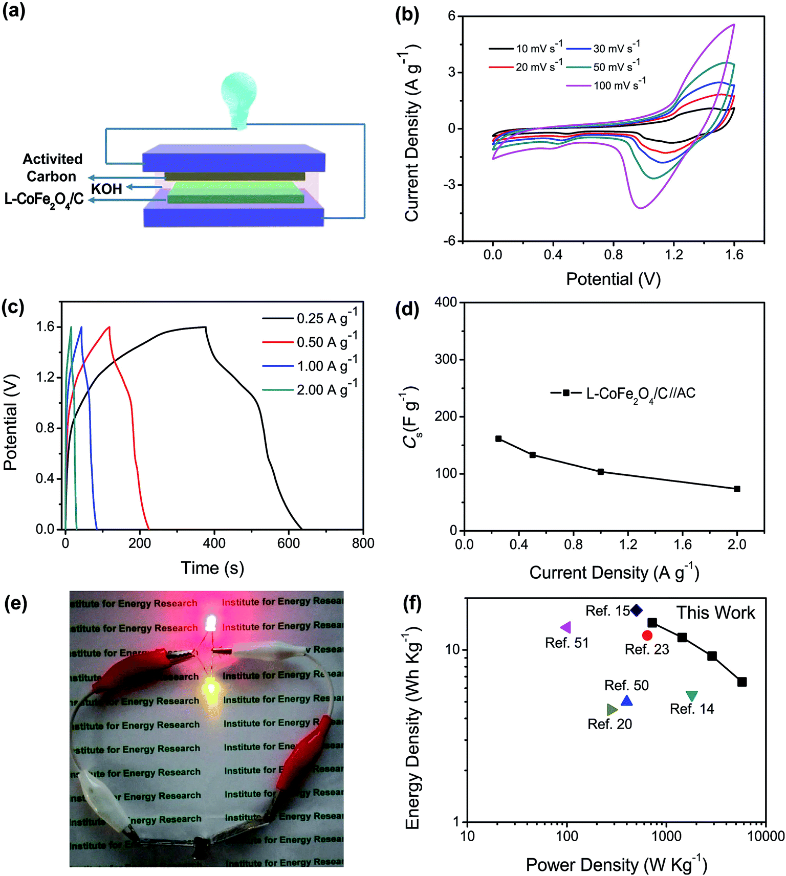 | ||
| Fig. 4 (a) The schematic illustration of the asymmetric supercapacitor configuration. (b) CV curves of the L-CoFe2O4/C//AC asymmetric supercapacitor at different scan rates. (c) GCD curves and (d) specific capacitances of the L-CoFe2O4/C//AC asymmetric supercapacitor at different current densities. (e) The red and yellow LEDs in parallel illuminated by two assembled L-CoFe2O4/C//AC asymmetric supercapacitor devices connected in series. (f) The Ragone plot of the L-CoFe2O4/C//AC asymmetric supercapacitor device in comparison with complex Fe-based asymmetric supercapacitors reported in the literature. | ||
According to their respective potential windows, the operating potential window of the asymmetric supercapacitor can be extended to 1.6 V due to the contribution of both the anode and cathode materials. Fig. 4b shows the CV curves of the L-CoFe2O4/C//AC asymmetric supercapacitor at various scan rates. It was obvious that all of the curves of the asymmetric supercapacitor maintained the same shapes without gradual deviation, showing the excellent supercapacitive performance.
The GCD curves of the as-assembled L-CoFe2O4/C//AC asymmetric supercapacitor shown in Fig. 4c at current rates from 0.25 to 2.0 A g−1 prove the supercapacitive behaviors. The supercapacitor delivered a maximum specific capacitance of 160 F g−1 at 0.25 A g−1 (Fig. 4d). This value is significantly better than that of previously reported supercapacitors (Table 2), such as: CoFe2O4//rGO (38 F g−1 at 3 mA cm−2),30 ZnFe2O4//Ni(OH)2 (118 F g−1 at 5 mA cm−2),60 MnFe2O4//LiMn2O4 (50 F g−1 at 1 A g−1),16 ZnFe2O4//ZnFe2O4 (32.22 F g−1 at 1 A g−1)22 and ZnFe2O4//Ni(OH)2 (93 F g−1 at 0.6 mA cm−2).20 The coulombic efficiency of the L-CoFe2O4/C//AC asymmetric supercapacitor shown in Fig. S7† remains at about 95.5% during the charge/discharge process. Two L-CoFe2O4/C//AC supercapacitors in series can easily illuminate two commercial light-emitting diode (LED) indicators (Fig. 4e), suggesting good electrochemical properties for energy storage applications.
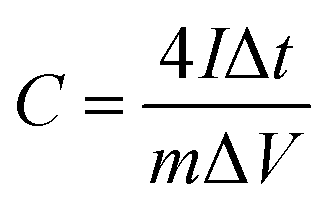
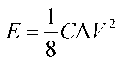
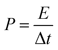
The energy/power densities were calculated from eqn (2)–(4). It can be seen that the maximum energy density of the L-CoFe2O4/C//AC asymmetric supercapacitor reaches 14.38 W h kg−1 at a power density of 0.72 kW kg−1 and the maximum power density is 5.76 kW kg−1 at 6.53 W h kg−1 (Fig. 4f). A rough comparison of the energy/power densities shown in Fig. 4f and listed in Table 2 indicates the superiority of our L-CoFe2O4/C//AC asymmetric supercapacitor compared with some of the mixed Fe-based asymmetric/symmetric supercapacitor devices, such as ZnFe2O4//ZnFe2O4 thin film,22 CoFe2O4 particles//rGO,30 MnFe2O4/graphene//MnFe2O4/graphene,61 MnFe2O4//LiMn2O4,16 and MnFe2O4/graphene/PANI//MnFe2O4/graphene/PANI.62 Fig. S8† shows the cycling life of the L-CoFe2O4/C//AC asymmetric supercapacitor at a current density of 1 A g−1. The specific capacitance was still about 76.6% after 800 charge–discharge cycles, demonstrating the superior cycling stability. The morphology and structure of the anode material are also preserved after over 800 cycles (inset of Fig. S8 and S9†). These combined results demonstrate the outstanding performance of the L-CoFe2O4/C//AC asymmetric supercapacitor and the electroactive material in practical applications.
Conclusions
In summary, the mesoporous low-crystalline CoFe2O4/C nanostructures were prepared by a facile citric acid assisted sol–gel approach and further heat treatment process. The mesoporous L-CoFe2O4/C composite displays a high surface area and superior electronic conductivity. Compared with the amorphous CoFe-precursor and the crystalized CoFe2O4 electrodes, the obtained mesoporous L-CoFe2O4/C electrode exhibits an excellent electrochemical performance, which can be attributed to the low-crystalline mesoporous structures, oxygen vacancies and carbon combination of the L-CoFe2O4/C. In addition, an L-CoFe2O4/C//AC asymmetric supercapacitor exhibits high energy density and power density, and exceeds most of the reported mixed Fe-based symmetric and asymmetric supercapacitors. The wide availability and great electrochemical properties of mesoporous L-CoFe2O4/C, combined with our convenient approach, make it appropriate for high performance energy storage devices in the future.Conflicts of interest
The authors declare that they have no competing interests.Acknowledgements
The authors would like to thank Doctor XieHuiqi from Fudan University for his characterization support. This work is financially supported by the National Natural Science Foundation of China for Youths (No. 51603092, 21506077 and 21705027), Natural Science Foundation of Jiangsu Province for Youths (BK20160537), the China Postdoctoral Science Foundation (No. 2016M591777 and 2016M590415), Jiangsu University Scientific Research Funding (15JDG160), the National Key R&D Program of China (No. 2017YFA0206901 and 2017YFA0206900), the Natural Science Foundation of Shandong Province (No. ZR2016HQ11) and a Project Funded by the Priority Academic Program Development of Jiangsu Higher Education Institutions.Notes and references
- M. Acerce, D. Voiry and M. Chhowalla, Nat. Nanotechnol., 2015, 10, 313–318 CrossRef CAS PubMed.
- P. Pachfule, D. Shinde, M. Majumder and Q. Xu, Nat. Chem., 2016, 8, 718–724 CrossRef CAS PubMed.
- B. Kong, C. Selomulya, G. F. Zheng and D. Y. Zhao, Chem. Soc. Rev., 2015, 44, 7997–8018 RSC.
- H. Jiang, H. X. Zhang, Y. Fu, S. J. Guo, Y. J. Hu, L. Zhang, Y. Liu, H. L. Liu and C. Z. Li, ACS Nano, 2016, 10, 1648–1654 CrossRef CAS PubMed.
- B. Kong, L. Zu, C. Peng, Y. Zhang, W. Zhang, J. Tang, C. Selomulya, L. Zhang, H. Chen, Y. Wang, Y. Liu, H. He, J. Wei, X. Lin, W. Luo, J. Yang, Z. Zhao, Y. Liu, J. Yang and D. Zhao, J. Am. Chem. Soc., 2016, 138, 16533 CrossRef CAS PubMed.
- B. Kong, J. Tang, Z. X. Wu, C. Selomulya, H. T. Wang, J. Wei, Y. C. Wang, G. F. Zheng and D. Y. Zhao, NPG Asia Mater., 2014, 6, e117 CrossRef CAS.
- M. S. Zhu, Y. Huang, Y. Huang, Z. X. Pei, Q. Xue, H. F. Li, H. Y. Geng and C. Y. Zhi, Adv. Funct. Mater., 2016, 26, 4481–4490 CrossRef CAS.
- Y. Zhao, M. Chen and L. M. Wu, Nanotechnology, 2016, 27, 342001 CrossRef PubMed.
- Y. Z. Zhang, T. Cheng, Y. Wang, W. Y. Lai, H. Pang and W. Huang, Adv. Mater., 2016, 28, 5242–5248 CrossRef CAS PubMed.
- H. Jiang, P. S. Lee and C. Z. Li, Energy Environ. Sci., 2013, 6, 41–53 CAS.
- Q. Y. Lv, S. Wang, H. Y. Sun, J. Luo, J. Xiao, J. W. Xiao, F. Xiao and S. Wang, Nano Lett., 2016, 16, 40–47 CrossRef CAS PubMed.
- Y. Zhao, L. F. Hu, S. Y. Zhao and L. Wu, Adv. Funct. Mater., 2016, 26, 4085–4093 CrossRef CAS.
- Z. Y. Zhang, W. Y. Li, R. J. Zou, W. P. Kang, Y. S. Chui, M. F. Yuen, C.-S. Lee and W. J. Zhang, J. Mater. Chem. A, 2015, 3, 6990–6997 CAS.
- L. R. Hou, L. Lian, L. H. Zhang, G. Pang, C. Z. Yuan and X. G. Zhang, Adv. Funct. Mater., 2015, 25, 238–246 CrossRef CAS.
- B. Senthilkumar, R. K. Selvan, P. Vinothbabu, I. Perelshtein and A. Gedanken, Mater. Chem. Phys., 2011, 130, 285–292 CrossRef CAS.
- Y.-P. Lin and N.-L. Wu, J. Power Sources, 2011, 196, 851–854 CrossRef CAS.
- K. V. Sankar and R. K. Selvan, J. Power Sources, 2015, 275, 399–407 CrossRef CAS.
- P. T. Sen and A. De, Electrochimi. Acta, 2010, 55, 4677–4684 CrossRef CAS.
- Z. Wang, X. Zhang, Y. Li, Z. T. Liu and Z. P. Hao, J. Mater. Chem. A, 2013, 1, 6393–6399 CAS.
- A. Shanmugavani and R. KalaiSelvan, RSC Adv., 2014, 4, 27022–27029 RSC.
- X. W. Hu, S. Liu, B. T. Qu and X. Z. You, ACS Appl. Mater. Interfaces, 2015, 7, 9972–9981 CAS.
- S. S. Raut and B. R. Sankapal, Electrochimi. Acta, 2016, 198, 203–211 CrossRef CAS.
- M. M. Vadiyar, S. C. Bhise, S. K. Patil, S. S. Kolekar, A. R. Shelke, N. G. Deshpande, J.-Y. Chang, K. S. Ghule and A. V. Ghule, Chem. Commun., 2016, 52, 2557–2560 RSC.
- Y. X. Zhang, X. D. Hao, Z. P. Diao, J. Li and Y. M. Guan, Mater. Lett., 2014, 123, 229–234 CrossRef CAS.
- P. Xiong, H. J. Huang and X. Wang, J. Power Sources, 2014, 245, 937–946 CrossRef CAS.
- Z. Wang, W. Jia, M. L. Jiang, C. Chen and Y. D. Li, Nano Res., 2016, 9, 2026–2033 CrossRef CAS.
- Y. Xiang, H. Wu, K. H. L. Zhang, M. Coto, T. Zhao, S. Chen, B. T. Dong, S. Y. Lu, A. Abdelkader, Y. Z. Guo, Y. F. Zhang, S. J. Ding, K. Xi and G. X. Gao, J. Mater. Chem. A, 2017, 5, 8062–8069 CAS.
- B. T. Dong, M. Y. Li, C. H. Xiao, D. W. Ding, G. X. Gao and S. J. Ding, Nanotechnology, 2017, 28, 055401 CrossRef PubMed.
- G. X. Gao, S. Y. Lu, B. T. Dong, Z. C. Zhang, Y. S. Zheng and S. J. Ding, J. Mater. Chem. A, 2015, 3, 4716–4721 CAS.
- K. V. Sankar, R. K. Selvan and D. Meyrick, RSC Adv., 2015, 5, 99959–99967 RSC.
- V. S. Kumbhar, A. D. Jagadale, N. M. Shinde and C. D. Lokhande, Appl. Surf. Sci., 2012, 259, 39–43 CrossRef CAS.
- H. B. Li, M. H. Yu, F. X. Wang, P. Liu, Y. Liang, J. Xiao, C. X. Wang, Y. X. Tong and G. W. Yang, Nat. Commun., 2013, 4, 1894 CrossRef CAS PubMed.
- H. B. Li, Y. Q. Gao, C. X. Wang and G. W. Yang, Adv. Energy Mater., 2015, 5, 1401767–1401775 CrossRef.
- H. Wu, Z. Lou, H. Yang and G. Z. Shen, Nanoscale, 2015, 7, 1921–1926 RSC.
- R. Z. Li, Y. M. Wang, C. Zhou, C. Wang, X. Ba, Y. Y. Li, X. T. Huang and J. P. Liu, Adv. Funct. Mater., 2015, 25, 5384–5394 CrossRef CAS.
- S. Gao, Y. F. Sun, F. C. Lei, L. Liang, J. W. Liu, W. T. Bi, B. C. Pan and Y. Xie, Angew. Chem., 2014, 53, 12789–12793 CrossRef CAS PubMed.
- Y. F. Ai, X. W. Geng, Z. Lou, Z. M. Wang and G. Z. Shen, ACS Appl. Mater. Interfaces, 2015, 7, 24204–24211 CAS.
- J. Deng, Y. S. Shao, N. Y. Gao, C. Q. Tan, S. Q. Zhou and X. H. Hu, J. Hazard. Mater., 2013, 262, 836–844 CrossRef CAS PubMed.
- G. X. Gao, S. Y. Lu, B. T. Dong, W. Yan, W. Wang, T. Zhao, C. Y. Lao, K. Xi, R. V. Kumar and S. J. Ding, J. Mater. Chem. A, 2016, 4, 10419–10424 CAS.
- G. X. Gao, S. Y. Lu, B. T. Dong, Y. Xiang, K. Xi and S. J. Ding, J. Mater. Chem. A, 2016, 4, 6264–6270 CAS.
- G. X. Gao, H. B. Wu, B. T. Dong, S. J. Ding and X. W. Lou, Adv. Sci., 2015, 2, 1400014 CrossRef PubMed.
- N. D. Kim, H. J. Yun, I. Nam, I. K. Song and J. Yi, Curr. Appl. Phys., 2012, 12, 1139–1143 CrossRef.
- Y. Fu, J. M. Song, Y. Q. Zhu and C. B. Cao, J. Power Sources, 2014, 262, 344–348 CrossRef CAS.
- J. P. Wang, S. L. Wang, Z. C. Huang and Y. M. Yu, J. Mater. Chem. A, 2014, 2, 17595–17601 CAS.
- D. B. Do, N. D. Phu, N. V. Hung, L. H. Hoang, L. T. M. Oanh, D. M. Thanh and N. V. Minh, IEEE Trans. Magn., 2014, 50, 1–4 CrossRef.
- J. Z. Chen, J. L. Xu, S. Zhou, N. Zhao and C.-P. Wong, Nano Energy, 2016, 21, 145–153 CrossRef CAS.
- M. Y. Zhu, X. Zhang, Y. Zhou, C. H. Zhuo, J. C. Huang and S. J. Li, RSC Adv., 2015, 5, 39270–39277 RSC.
- M. Zhang, X. Yang, X. F. Kan, X. Wang, L. Ma and M. Q. Jia, Electrochimi. Acta, 2013, 112, 727–734 CrossRef CAS.
- X. F. Lu, L. F. Gu, J. W. Wang, J. X. Wu, P. Q. Liao and G. R. Li, Adv. Mater., 2016, 29, 1604437 CrossRef PubMed.
- S. J. Peng, L. L. Li, Y. X. Hu, M. Srinivasan, F. Y. Cheng, J. Chen and S. Ramakrishna, ACS Nano, 2015, 9, 1945–1954 CrossRef CAS PubMed.
- B. Saravanakumar, K. K. Purushothaman and G. Muralidharan, ACS Appl. Mater. Interfaces, 2012, 4, 4484–4490 CAS.
- J. H. Kim, K. Zhu, Y. Yan, C. L. Perkins and A. J. Frank, Nano Lett., 2010, 10, 4099–4104 CrossRef CAS PubMed.
- C. Long, M. T. Zheng, Y. Xiao, B. F. Lei, H. W. Dong, H. R. Zhang, H. Hu and Y. L. Liu, ACS Appl. Mater. Interfaces, 2015, 7, 24419–24429 CAS.
- Y. Zhang, W. P. Sun, X. H. Rui, B. Li, H. T. Tan, G. L. Guo, S. Madhavi, Y. Zong and Q. Y. Yan, Small, 2015, 11, 3694–3702 CrossRef CAS PubMed.
- Q. Qu, L. Li, S. Tian, W. Guo, Y. Wu and R. Holze, J. Power Sources, 2010, 195, 2789–2794 CrossRef CAS.
- H. Inoue, Y. Namba and E. Higuchi, J. Power Sources, 2010, 195, 6239–6244 CrossRef CAS.
- Q. Q. Qin, X. D. Du, C. X. Xu, S. G. Huang, W. J. Wang, Y. Zhang, J. Yan, J. Q. Liu and Y. C. Wu, J. Electrochem. Soc., 2017, 164, A1952–A1957 CrossRef CAS.
- Z. Gao, W. L. Yang, J. Wang, N. N. Song and X. D. Li, Nano Energy, 2015, 13, 306–317 CrossRef CAS.
- M. H. Yu, Y. C. Huang, C. Li, Y. X. Zeng, W. Wang, Y. Li, P. P. Fang, X. H. Lu and Y. X. Tong, Adv. Funct. Mater., 2014, 25, 324–330 CrossRef.
- M. M. Vadiyar, S. C. Bhise, S. S. Kolekar, J.-Y. Chang, K. S. Ghule and A. V. Ghule, J. Mater. Chem. A, 2016, 4, 3504–3512 CAS.
- W. H. Cai, T. Lai, W. L. Dai and J. S. Ye, J. Power Sources, 2014, 255, 170–178 CrossRef CAS.
- P. Xiong, C. Y. Hu, Y. Fan, W. Y. Zhang, J. W. Zhu and X. Wang, J. Power Sources, 2014, 266, 384–392 CrossRef CAS.
Footnotes |
| † Electronic supplementary information (ESI) available. See DOI: 10.1039/c7ra11741h |
| ‡ All the authors performed the experiments. Yan Zhao wrote the paper. Yuanguo Xu, Le Xu, Jiabiao Lian, Shuquan Huang, Jingxia Qiu and Yunpeng Huang collected data and carried out all analysis. Biao Kong and Huaming Li conceptualized the idea and revised the manuscript. |
| This journal is © The Royal Society of Chemistry 2017 |