 Open Access Article
Creative Commons Attribution 3.0 Unported Licence
Large-scale preparation of macro-porous silica microspheres via sol–gel composite particles and a spray drying process†
Xin Fan *a,
Songdong Lia,
Yuehuan Wu*a and
Lin Niub
aDepartment of Chemistry and Chemical Engineering, Taiyuan Institute of Technology, Taiyuan 030008, China. E-mail: fanxintit@163.com; wuyuehuan123@126.com
bSchool of Chemistry and Chemical Engineering, South China University of Technology, Guangzhou 510640, China
First published on 12th December 2017
Abstract
One novel method of preparing macro-porous silica microspheres on a large scale is presented here, which utilized spray drying silica/polymer composite particles and calcination. Silica/polymer composite particles were prepared via sol–gel reaction of siloxane on polymer latex particles, which were obtained via cationic emulsion polymerization. Afterwards the latex of composite particles was spray dried to produce hollow microspheres, and the microspheres were calcinated to remove the polymer particle templates so that a porous structure could be generated. With these common industrial procedures, macro-porous silica microspheres could be prepared on a large scale. Parameters like polymer particle glass transition temperature and cationic monomer amount in emulsion polymerization were explored. It was found that, with a glass transition temperature of 10 °C and a cationic monomer amount of 5.0 wt%, composite particles could well coalesce during spray drying and generate uniform macro-porous structure.
1. Introduction
Microspheres with unique, precise structures have attracted researcher interest for decades, and a number of microsphere morphologies have been created, e.g. core–shell,1–3 raspberry-like,4–6 hollow,7,8 porous,9,10 Janus,11,12 yolk13 and so on. Among these, hollow-porous structures are especially hot in many fields, due to the hollow loading room in the core, porous releasing channels in the shell and large specific surface areas. Yang & Xie, et al. synthesized hollow mesoporous silica nanoparticles (HMS) as the core and multifunctional amphiphilic FA-TDA-DBA (FTD) ligands as the encapsulating shell. The HMS@FTD could provide a physical and structural stability and deliver the hydrophobic drug to the target tumor cells.14 Chen & Xie, et al. prepared the HPSi nanocomposite with Ag nanoparticles, which used in lithium-ion storage. The hollow and the porosity structure would reduce the diffusion resistance in charge-transfer reactions and show desirable electrochemical features.15 Xia et al. synthesized monodisperse large-porous silica microspheres which could be used in the separation and analysis of the proteins and peptides.16,17 Taher synthesized meso/macro-porous silica microspheres (MSM), which the surface was coated with polydopamine (PDA). They used MSM@PDA as an adsorbent for the removal of MB from aqueous solutions.18Currently the main methods towards macro-porous silica microspheres are sol–gel template method,19–21 W/O emulsion method22 and microfluidic method.23 Sol–gel template method is commonly used to prepare inorganic/polymer composite particles, utilizing the hydrolysis–condensation reactions of precursors on template surfaces. Through adjusting the surface functional groups and reaction parameters (pH, temperature, time, etc.), different composite particles could be obtained.24–26 However there exist certain limitations in this method. First, the sol–gel reaction must be conducted in solvent and the separation/collection of final products would be difficult; secondly, the porous structure is mesoporous and the precise structure could not be controlled. Spray drying is a conventional technique in chemical industry, and it is well known that hollow microspheres could be obtained after drying due to the water evaporation from droplets. There have been reports about macro-porous microspheres prepared via spray drying, in which blends of polymer particles and silica sol were used.27–29 In this method, polymer particles were randomly dispersed in silica sol and acted as sacrifice template, therefore the uniform content of porous structure would be influenced. Meanwhile without the coalescence of polymer particles during spray drying, high amount of silica sol must be added in blends to ensure the structural robustness of the microsphere and final porous structure, which made it possible to prepare exquisite microspheres.
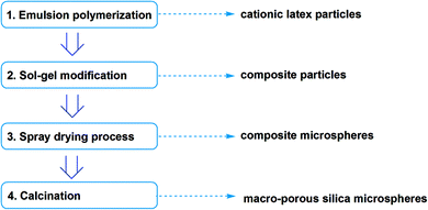
Here we reported one method combining composite particles method and spray drying granulation. Based on cationic polymer latex, sol–gel modification was conducted towards silica shell composite particles. Then dispersion of composite particle was spray dried to be hollow composite microspheres, and the composite microspheres could be made into porous by calcination to remove polymer compositions. Every step in this method is common industrial process so that the macro-porous silica microspheres are possible to be prepared in large scale, while the pore size could be tuned with template latex particle size.
2. Experimental
2.1 Materials
Tetraethoxysilane (TEOS, 100% purity, Guanghua, Guangzhou), 2,2′-azobis(isobutyramidine) 2HCl (AIBA, 100% purity, Runxing, Qingdao) were all purchased in AR grade. Acryloyloxyethyl trimethyl ammonium chloride (MTC, Alfa) was supplied as 72.0 wt% aqueous solution. All the above reagents were used as accepted without further purification. Methyl methacrylate (MMA, 100% purity, Asahi Kasei), butyl acrylate (BA, 100% purity, Asahi Kasei) were distilled to remove inhibitor before use. DI water was used throughout (Scheme 1).2.2 Preparation methods
First is soap-free cationic emulsion polymerization (step 1) towards cationic latex particles, which acted as templates in further steps. Electrolyte (NaCl 0.05 g) and initiator (AIBA 0.40 g) were first dissolved in water (190.0 g) and charged into vessel, afterwards heating temperature was increased to 60 °C. Then acrylate monomers (60.0 g) were added with peristaltic pump for 5 h, afterwards cationic monomer solution (MTC 0.6 g, AIBA 0.1 g, DI water 50.0 g) was added with peristaltic pump for another 5 h. N2 bubbling was kept all through the reaction process. The solid content of resultant latex was approx. 20.30 wt%.Second is sol–gel modification (step 2) towards silica-shell composite particles. In this step cationic latex (50.0 g) was taken out and its pH value was adjusted to 3.0 with 1.0 wt% HCl solution. TEOS (2.5 g) was added into above latex and stirred for 6 h under 45 °C, then aged for 3 days.
The modified composite latex was charged into spray dryer (inlet temperature 105 °C) for granulation (step 3). After that the resultant microspheres were calcinated under air atmosphere towards macro-porous microspheres (step 4), and the calcination temperature setting was 200 °C/15 min to 700 °C/30 min.
2.3 Characterization
The microstructure of the microspheres was observed with transmission electron microscopy (TEM, Hitachi, H-7650) without staining as well as scanning electron microscopy (SEM, LEO, 1530VP). To analyze the chemical composition of latex solid and microspheres, latex was dried under 70 °C, dispersed in KBr tablets and analyzed with Fourier transform infrared spectrophotometer (FTIR, Hitachi TENSOR-27, parameters: resolution 4 cm−1 and 20 scans). The silica content of composite latex was determined with thermal analyzer (TGA, Netzsch, STA-449C-Jupiter), under constant heating rate of 10 °C min−1 from 30 to 800 °C under air atmosphere. The particle size of latex was measured with dynamic light scattering (DLS) using Malvern laser particle sizer (Malvern, 2S-Nano-S). The specific surface areas of samples were measured via the TriStar II analyzer based on the nitrogen adsorption/desorption. The pore-size distribution was calculated using the Barrett–Joyner–Halenda (BJH) method.3. Results and discussions
3.1 Chemical composition changes
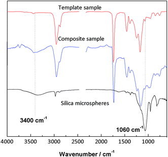
Sol–gel modification of cationic latex particles with siloxane is commonly used in the preparation of composite materials. Here we studied the chemical changes of particles with FTIR, TGA and DSC, and the results were shown as below. The composite particles were centrifuged and washed repeatedly to separate composite particles with free polysiloxane oligomers. From the spectra it could be found that clear Si–OH (3400 cm−1) and Si–O–Si (1060 cm−1) peaks appeared after sol–gel modification, demonstrating the generation of silica shells around latex particles (Fig. 1).3.2 Effects of latex Tg
It is well known that not all latex could be spray dried and this depends on the glass transition temperature (Tg) of the latex polymer.30 Only when the Tg of latex polymer or latex particle shell exceed the outlet temperature of spray drying, the latex could pass the drying process to become free-flowing powders without caking or sticking. Sol–gel modification also could help in this process, as the siloxane added could form silica shell around latex particles to improve heat tolerance. However, latex particles were the main polymeric binding composition in the spray-dried composite microspheres, so that the latex Tg could not be too high to ensure the binder effect (Fig. 2).Soap-free cationic emulsion polymerization was selected to prepare template latex. This is because that the sol–gel polysiloxane oligomers are always negative-charged, which could be attracted onto cationic latex particle surfaces, therefore sol–gel efficiency could be improved. Without influence of emulsifier the attraction could be more targeting. The pH value of 3.0 also is due to the same reason, for quaternary ammonium groups are fully ionized in acidic environment.
Here series of cationic latex with different Tg were prepared and evaluated, in order to obtain the optimal Tg point of binding and heat tolerance balance. The Tg of polymer was calculated according to Flory–Fox equation. MMA and BA combinations were designed and listed as below (Table 1).
| BA/MMA weight, g | 40.7/19.3 | 36.0/24.0 | 32.0/28.0 | 28.0/32.0 | 24.0/36.0 | 20.7/39.3 |
| Theoretical Tg, °C | −20 | −10 | 0 | 10 | 20 | 30 |
| Spray drying result | Caking | Caking | Slight caking | Free-flowing powders | Free-flowing powders | Free-flowing powders |
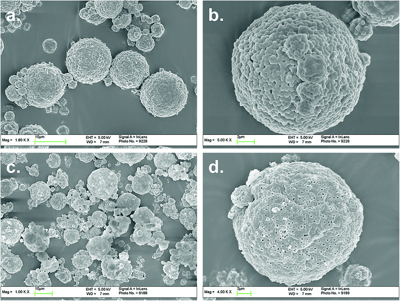
From above results it could be found that 10–20 °C might be the optimal point of latex Tg. The spray dried powders were observed with SEM and the powder morphologies were demonstrated as below.
3.3 Effects of MTC amounts
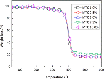
Acryloyloxyethyltrimethyl ammonium chloride (MTC) is one type of cationic water-soluble monomer. By introducing MTC into emulsion polymerization, the colloidal stability and surface charge density of latex could be enhanced. The electrostatic attraction of latex particles and polysiloxane oligomers could be strengthened, which could improve the composite efficiency. However due to the solubility difference MTC tends to self-polymerize instead of co-polymerizing with MMA/BA, hence too much MTC in emulsion polymerization would result in the formation of soluble oligomers in water phase and hinder the concentration of polysiloxane onto latex particle surfaces.Based on the recipe of Tg = 10 °C, the addition amount of MTC was studied as shown in Table 2. The influence of MTC amount on the cationic emulsion polymerization, as the particle diameters increased with MTC ratio: 351, 362, 374, 400, 587 nm respectively, due to the increasing of particle hydraulic volumes. From the spray drying results there appeared no differences depending on MTC amount. But if the morphologies of microspheres were observed, it could be found that with high MTC amount the coalescence content of composite particles in the microspheres (Fig. 4) were greater compared with that in Fig. 3. This suggested that with high MTC amount, the silica shells of composite particles were thinner and more polysiloxane dispersed in water, resulting in better coalescence and less pore generation. This could be proved with TGA results of composite particles in Fig. 5. It could be seen that with the increasing of MTC ratio, silica amounts in composite particles demonstrate turning point on 7.5 wt%. In order to balance the coalescence content and microsphere integrity, MTC ratio of 5.0 wt% was selected for further experiments.
| MTC amount, g | 0.6 | 1.5 | 3 | 4.5 | 6 |
| MTC ratio based on acrylate monomers | 1.0 wt% | 2.5 wt% | 5.0 wt% | 7.5 wt% | 10.0 wt% |
| Spray drying results | Free-flowing powders | Free-flowing powders | Free-flowing powders | Free-flowing powders | Free-flowing powders |
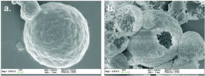 | ||
| Fig. 4 The SEM images of composite microspheres and corresponding hollow microspheres, MTC ratio 10.0 wt%. | ||
3.4 Characteristics of macro-porous microspheres
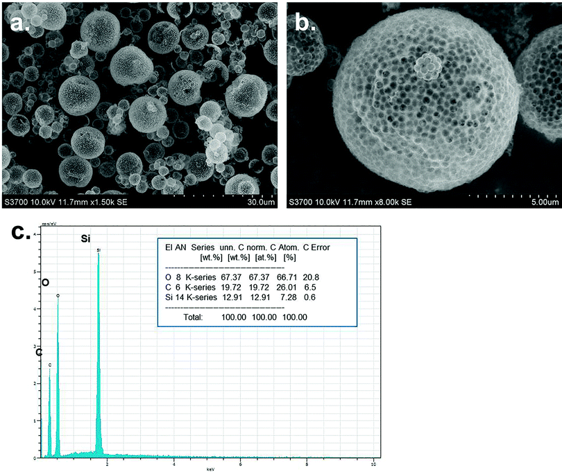
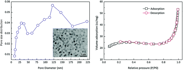
Based on above experiments, macro-porous microspheres with good morphology could be prepared as shown in Fig. 6. The chemical composition of these microspheres was silica according to EDX analysis. The pore distribution and adsorption/desorption curve were shown in Fig. 7. It could be found that the pore size mainly located on the range of 100–250 nm which was in accordance with SEM observation. This was because that, the porous structure was generated via the sacrificing of the polymer particles during calcinations, so the pore size should be accordance with polymer particle size. In the embedded figure of Fig. 7, honeycomb framework could be observed which was formed via coalescence and removing of polymer particles. The adsorption/desorption behavior followed the macroporous materials type.4. Conclusion
Macro-porous silica microspheres were prepared by combining composite particles and spray drying granulation. Soap-free cationic emulsion polymerization was used to prepare polymer template latex. Afterwards the latex was sol–gel modified and the composite dispersion was spry dried towards hollow composite microspheres. Finally composite microspheres were calcinated to remove polymer particle cores and create porous structure inside microsphere shells. Latex Tg and MTC amount were studied, based on their influences of microsphere morphology, and Tg = 10 °C and MTC ratio = 5.0 wt% were optimal parameters. The macro-porous silica microspheres potential applications as adsorption and separation, protein purification, drug carriers, catalyst supports, supercapacitors, fuel cells and so on.Conflicts of interest
There are no conflicts to declare.Acknowledgements
It is acknowledged that this work was supported by the Key Research Plan Program of Shanxi Province (No. 201603D421038), Shanxi Province Foundation for Returness (2016-114), the Start-Up Funds of Taiyuan Institute of Technology and the Program for the Innovative Talents of Taiyuan Institute of Technology.References
- K. Zhang, H. Chen, X. Chen, Z. Chen, Z. Cui and B. Yang, Macromol. Mater. Eng., 2003, 288(4), 380–385 CrossRef CAS.
- L. Niu, Z. Xia, L. Lei, Y. Zhang and L. Zhong, J. Appl. Polym. Sci., 2013, 128(6), 4237–4244 CrossRef CAS.
- K. P. Velikov, A. Moroz and A. van Blaaderen, Appl. Phys. Lett., 2002, 80(1), 49–51 CrossRef CAS.
- X. Fan, L. Niu, Y. Wu, J. Cheng and Z. Yang, Appl. Surf. Sci., 2015, 332, 393–402 CrossRef CAS.
- X. Fan, L. Niu and Z. Xia, Colloid Polym. Sci., 2014, 292(12), 3251–3259 CAS.
- X. Fan, L. Zheng, J. Cheng, S. Xu, X. Wen, Z. Cai and Z. Yang, Surf. Coat. Technol., 2012, 213, 90–97 CrossRef CAS.
- C. E. Fowler, D. Khushalani and S. Mann, Chem. Commun., 2001,(19), 2028–2029 RSC.
- C. E. Fowler, D. Khushalani and S. Mann, J. Mater. Chem., 2001, 11(8), 1968–1971 RSC.
- J. J. Kirkland, F. A. Truszkowski, C. H. Dilks and G. S. Engel, J. Chromatogr. A, 2000, 890(1), 3–13 CrossRef CAS PubMed.
- R. Wang, Y. Zhang, G. Ma and Z. Su, J. Appl. Polym. Sci., 2006, 102(5), 5018–5027 CrossRef CAS.
- J. Zhang, J. Jin and H. Zhao, Langmuir, 2009, 25(11), 6431–6437 CrossRef CAS PubMed.
- A. Perro, S. Reculusa, S. Ravaine, E. Bourgeat-Lami and E. Duguet, J. Mater. Chem., 2005, 15(35–36), 3745–3760 RSC.
- W. Li, Y. Deng, Z. Wu, X. Qian, J. Yang, Y. Wang and D. Zhao, J. Am. Chem. Soc., 2011, 133(40), 15830–15833 CrossRef CAS PubMed.
- S. Yang, D. Chen, N. Li, Q. Xu, H. Li, F. Gu, J. Xie and J. Lu, Small, 2016, 12(3), 360–370 CrossRef CAS PubMed.
- D. Chen, X. Mei, G. Ji, M. Lu, J. Xie, J. Lu and J. Lee, Angew. Chem., Int. Ed., 2012, 51, 2409–2413 CrossRef CAS PubMed.
- H. Xia, G. Wan, F. Yang, J. Wang and Q. Bai, Mater. Lett., 2016, 180(1), 19–22 CrossRef CAS.
- H. Xia, G. Wan, J. Zhao, J. Liu and Q. Bai, J. Chromatogr. A, 2016, 1471(4), 138–144 CrossRef CAS PubMed.
- T. Ataei-Germi and A. Nematollahzadeh, J. Colloid Interface Sci., 2016, 470(15), 172–182 CrossRef CAS PubMed.
- Z. Z. Li, L. X. Wen, L. Shao and J. F. Chen, J. Controlled Release, 2004, 98(2), 245–254 CrossRef CAS PubMed.
- X. Du and J. He, Langmuir, 2010, 26(12), 10057–10062 CrossRef CAS PubMed.
- J. He, C. Yang, X. Xiong and B. Jiang, J. Polym. Sci., Part A: Polym. Chem., 2012, 50(14), 2889–2897 CrossRef CAS.
- X. He, X. Ge, H. Liu, M. Wang and Z. Zhang, J. Polym. Sci., Part A: Polym. Chem., 2007, 45(5), 933–941 CrossRef CAS.
- H. Zhang, X. J. Ju, R. Xie, C. J. Cheng, P. W. Ren and L. Y. Chu, J. Colloid Interface Sci., 2009, 336(1), 235–243 CrossRef CAS PubMed.
- B. G. Trewyn, I. I. Slowing and S. Giri, Acc. Chem. Res., 2007, 40(9), 846–853 CrossRef CAS PubMed.
- J. C. Song, F. F. Xue, Z. Y. Lu and Z. Y. Sun, Chem. Commun., 2015, 51(52), 10517–10520 RSC.
- Y. Sun, H. Sai and K. A. Spoth, Nano Lett., 2015, 16(1), 651–655 CrossRef PubMed.
- S. Y. Lee, L. Gradon and S. Janeczko, ACS Nano, 2010, 4(8), 4717–4724 CrossRef CAS PubMed.
- F. Iskandar, Mikrajuddin and K. Okuyama, Nano Lett., 2001, 1(5), 231–234 CrossRef CAS.
- F. Iskandar, Mikrajuddin and K. Okuyama, Nano Lett., 2002, 2(4), 389–392 CrossRef CAS.
- L. Niu, L. Lei and Z. Xia, J. Adhes. Sci. Technol., 2013, 27(13), 1432–1445 CrossRef CAS.
Footnote |
| † Electronic supplementary information (ESI) available. See DOI: 10.1039/c7ra11649g |
| This journal is © The Royal Society of Chemistry 2017 |

