 Open Access Article
Degradation of battery separators under charge–discharge cycles
X. Zhanga,
J. Zhua and
E. Sahraei *ab
*ab
aImpact and Crashworthiness Lab, Department of Mechanical Engineering, MIT, Camridge, MA, USA
bElectric Vehicle Safety Lab, Department of Mechanical Engineering, George Mason University, Fairfax, VA, USA. E-mail: esahraei@gmu.edu
First published on 12th December 2017
Abstract
Researchers have reported on the electrochemical aging of lithium-ion batteries. The mechanisms of battery capacity loss, such as consumption of electrolytes and fading of electrodes, commonly seen as fracture of coatings, have been studied intensively. The widely used polymeric separators sandwiched between cathode and anode, which do not directly contribute to the electrochemical properties of the cell, are usually taken as chemically, thermally and structurally stable materials. In this paper, the degradation of a dry processed trilayer separator due to charge–discharge cycles is investigated. It has been found that the separators that underwent higher cycles failed at lower lateral punch force and smaller deformation. Live cell tests also indicate that the deformation and force intensity at the onset of short circuit decreased for a cell after 1200 cycles compared to those for a non-cycled cell, when under lateral indentation. Different characterization methods were used to understand this charge–discharge induced mechanical aging. SEM through-thickness views of the separators show no significant pore size change, but reaction products accumulated in pores of the separator middle layer. FTIR (Fourier Transform Infrared) examination of the surfaces of those separators shows there was no apparent chemical bond change on the surface of the separator during charging and discharging process.
Introduction
The charge and discharge induced aging of lithium-ion batteries, mainly the capacity loss of the battery cells after years of operation, is still a big challenge for the fast-growing market of electric vehicles worldwide. Researchers are continuously studying the aging mechanism of cathodes and anodes, such as fracture of chemical coatings, formation of solid electrolyte interface, and degradation of active materials.1–7 On the other hand, the degradation of battery separators during charge and discharge cycles, which is not directly related to capacity loss, has not been investigated that well.Lithium-ion battery separators, typically made of polyolefins, such as polyethylene (PE), polypropylene (PP), or their combination, prevent contact between the cathode and anode.8 The failure of separators under abuse loading conditions will directly lead to internal short circuit and potential thermal run away. The mechanical properties of polymeric-based separators are temperature, loading rate and loading history dependent.9 During cycling of lithium-ion batteries in electric vehicles (EVs), besides charge–discharge, the battery components experience thermal and mechanical cycling as well. Therefore, there is a need to understand the extent of potential degradation of the separator under normal operating conditions in EVs.
In previous work, our research group has studied mechanical properties of various battery components taken out of fresh cells or before consumed in a cell.10–15 Mechanical properties of fresh cells and components have been used to develop finite element models for the battery cells. When batteries are used in automotive applications, an understanding of mechanical properties are essential to manufacturers. The vehicle design process is usually driven by simulation of vehicle deformations in case of an accident, and a finite element model of the battery is used to design the protective structure around it, in order to prevent deformation and short circuit. It is of utmost importance to the manufacturers to know how such battery models should be adjusted to account for degradation during life of the vehicle, and one of the most important components affecting the mechanical failure and resultant short circuit in a cell is the battery separator.
In this paper, the mechanical properties of separators from disassembled fresh cells and cells with various charge–discharge cycles were compared. The separators studied were dry processed trilayer separators (PP/PE/PP). Dry processed separators are the most widely used separators in the EV industry due to their cheap cost, and trilayer separators are very popular due to their good thermal properties.16 Uniaxial tensile tests and biaxial punch tests were carried out on separator samples. We found that separators from long cycled cells became significantly weaker under biaxial loading compared to those from fresh cells. This indicates adverse effects of aging. Lateral indentation of live cells show that aged cells had smaller displacement and force to short circuit. Scanning electron microscope (SEM) images of cross sectional views of separators with different cycle numbers were compared as well. There was no significant change in the microstructure of the cycled separators. However, traces of particle deposits in the pores may explain the loss of strength. Wide angle X-ray diffraction (XRD) images indicate no obvious crystalline orientation change. Infrared spectroscopy characterization of separators gives additional explanation about the potential aging mechanisms.
Experimental work
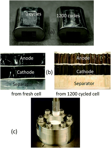
The battery cells in this study had an elliptical shape and a nickel oxide chemistry. The dimensions were 64.8 mm by 37.2 mm by 19.1 mm and their nominal capacity was 5.3 A h. The cells were fabricated at the same time and then cycled with 0.2C discharge rate and 0.7C charge rate under room temperature. The upper and lower cutoff voltage were set to 4.2 V and 2.75 V, respectively. Cells became inflated as they went under larger number of cycles. Fig. 1a shows the comparison of cells with 0 and 1200 cycles. Cells underwent 0, 50, 100, 325 and 1200 cycles were used for the study. Separators of these five cells were extracted and washed with Dimethyl Carbonate (DMC). These separators with a thickness of 16 μm were dry processed trilayer separators (PP/PE/PP). The color of separator changed for cells with higher cycles. For the cell with 1200 cycles, the separator was almost brown, as shown in Fig. 1b. Delamination of cathode and anode coatings was observed for the higher cycled cells. In this study no distinction was made between degradation due to calendar life and cycling induced aging. As the cells were manufactured and tested within same time frame, the only difference between the fresh and cycled cells were due to the number of cycles.Uniaxial tensile specimens were prepared according to ASTM D882 for thin films, having a strip shape with a uniform width of 10 mm as explained in two publications by Zhang et al. 2016.13,15 The strip specimen length was fixed as 60 mm and the gauge length was chosen as 35 mm. Following Sheidaei,17 to have enhanced precision for the width and improve quality of cut, a sharp razor was used to cut specimens while the separator was sandwiched between 5 mm Cartesian graph paper. The specimens were cut along machine direction (MD), transverse direction (TD) and diagonal direction (DD). An Instron 5944 uniaxial tensile machine with 100 N load cell and a constant 25 mm min−1 speed was used to perform the tests. Each test scenario was repeated five times.
Biaxial punch specimens with a diameter of 45 mm were cut by a hole puncher. The specimens were tightly fixed on a fixture with interior radius of 16 mm. Four Teflon hemispherical punch heads with diameters from 25.4 mm to 3.175 mm were used to apply the load, as shown in Fig. 1c. The tests were conducted by the same Instron machine and the loading speed was set to 12 mm min−1. Each test scenario was repeated twice.
To investigate structural changes, Helios nanolab dual beam microscope with focused ion beam (FIB) was used to obtain cross sectional views of fresh and cycled separators along MD and TD. Additionally, energy-dispersive X-ray spectroscopy (EDS) was applied to determine the chemical elements along the cross section. Between different sample preparation methods such as polishing the epoxy-impregnated sample, milling sample with ion beam cross section polisher and breaking of brittle separator sample in liquid nitrogen, FIB-SEM is found to be the best in terms of time and efforts of sample preparation and quality of final image. This method was also employed in available literature.18 Wide-angle X-ray diffraction (XRD) was adapted to check the change of crystalline orientations. Thermo Fisher Fourier Transform Infrared (FTIR) microscope provided a comparison of polymer chain changes between separators from 0 cycled and 1200 cycled cells.
In addition to tests on separators, local indentation tests on full cells with 0 and 1200 cycles were conducted with a 12.5 mm steel hemispherical punch head and 1 mm min−1 loading speed. Voltage of each cell was monitored during the tests. Tests stopped when a short circuit was detected from a drop in voltage.
Results and discussion
Uniaxial tensile test results for separators with different cycles are shown in Fig. 2. The stress–strain curves before failure in TD, MD, and DD did not show any noticeable differences. Therefore, the uniaxial tensile tests results indicate that the charge–discharge cycles did not influence the plasticity and material response of the separator. However, the failure strains in uniaxial tests highly depends on the cutting quality of strip specimens,13 which makes these tests not suitable for failure strain comparison. On the other hand, during biaxial punch tests, edges of separator specimen is held inside a tight fixture and the loading and deformation is applied in the center. Therefore this type of loading results in failure in the center of specimen far from the edges which may have imperfection due to the cutting process. As a result, the biaxial tests that remove effects of edge imperfections were ideal to check if failure strains have changed due to cycling.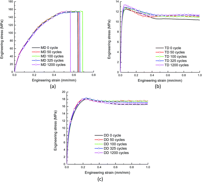 | ||
| Fig. 2 Engineering stress–strain curves of separators with different cycles in machine direction, transverse direction and diagonal direction. (a) MD. (b) TD. (c) DD. | ||
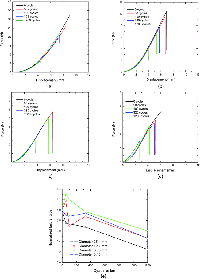
Fig. 3a–d shows the biaxial loading test results with four punch heads. The evolution of the force–displacement curves is comparable, while the failure forces are much smaller for the separators with 1200 cycles. This shows the loss of puncture strength for the separators with high number of charge–discharge cycles. Fig. 3e shows the failure force vs. cycle number curves for all four punch head sizes, where the failure forces were first averaged based on the two repeated tests and then normalized over the average force of separators with 0 cycle for better illustration. Although the failure force of separator with 50 and 100 cycles was scattered with different punch heads, the general trend is clear: with increasing cycle numbers, the separator became weaker under biaxial loading. Similar decrease of failure properties were also reported as the results of physical degradation of bulk PP.19,20
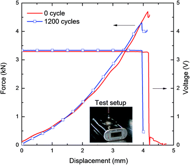
In order to understand how the degradation at separator level affects the mechanical strength at cell level, indentation tests with a hemispherical punch of 12.6 mm were performed on battery cells. This test is often used to calibrate short circuit strength of batteries in case of mechanical abuse, and the level of force and deformation tolerated by a fresh cell has been used in development of finite element models for battery cells. Lateral indentation test results of two live cells with 0 and 1200 cycles are shown in Fig. 4. Force, displacement, and voltage were measured during the tests. A short circuit in each cell was marked by a drop in voltage coincident with a local peak in force. The cell with 1200 cycles failed/short circuited at a smaller force and displacement. This indicates that a loss of puncture strength at separator level translates to a reduced tolerance to local indentation for high cycled batteries at cell level as well. It should be noted that many factors, such as SEI accumulation on anode surface, swelling in each charge–discharge cycle, induced plastic deformation of shell casing and/or jellyroll, and generation of gases lead to the final inflation at the cell level. However, the mechanical strength (as observed from the force–displacement curves) did not show any significant change due to the inflation. This suggests that the inflation mostly generated gap between the layers/components but did not change the materials in a significant way.
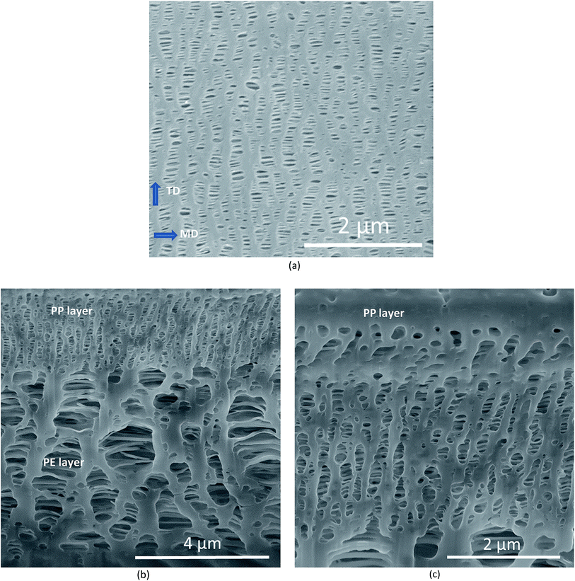
To understand the causes of degradation, possibly both physical and chemical aging, cross sectional views of the 16 μm thick separator prepared by FIB-SEM was used to check the changes in microstructure. Cross sections were investigated in three directions, on top surface, on a surface cut perpendicular to TD and another surface perpendicular to MD. Fig. 5 shows the SEM pictures for a separator taken out of a fresh cell undergone no cycling. Fig. 5a shows the orientation of the bulk material and fibril sections on the top surface of separator (PP layer). Fig. 5b and c show the cross-sectional views (top surface PP layer and central PE layer) of the separator on the surface perpendicular to TD. The pores on the top layer (PP) are smaller than 0.5 μ, while majority of the pores in the central (PE) layer are about 1 μ.
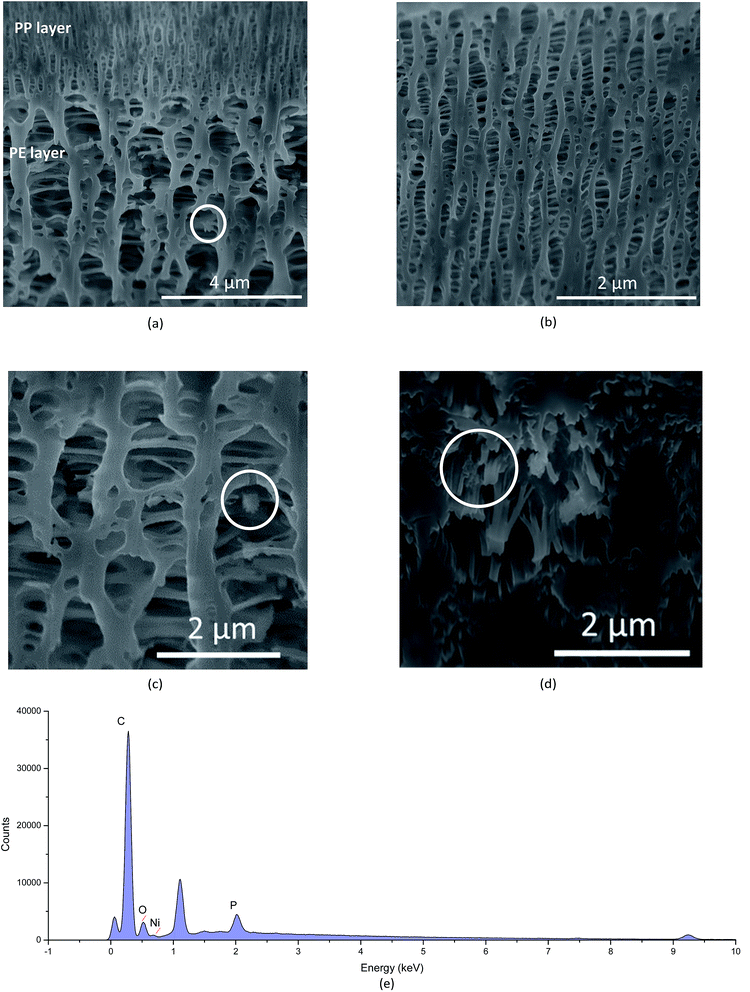
Fig. 6 shows the SEM pictures of the separator from a 1200 cycled cell. No obvious structure change was seen from these cross-sectional SEM images of 1200 cycled separators as compared to the 0 cycled separator. The pattern and pore sizes of PP and PE layers remains similar between the separators from these two cells. However, particles, potentially chemical reaction products, were accumulated inside the pores of the 1200 cycled separator around the fibrils of PE layer, as seen in Fig. 6a and magnified in circles in Fig. 6c and d. SEM/EDS analysis of the cross section of PE region showed that elements of nickel, oxygen and phosphorus were found in the cycled cell cross section (see Fig. 6e). This may indicate potential chemical reactions between the active material of nickel and the electrolyte that creates the chemical deposits seen in the pores of 1200 cycled separator. Such deposits were not seen in the PP layers of the separator.
To examine the crystalline orientation change during the charge and discharge cycles, wide angle XRD was applied. The diffraction patterns of separators with 0 and 1200 cycles are shown in Fig. 7a and b. This analysis indicates that there is no significant change in orientation of the crystalline structures of the separator due to charge–discharge cycles. FTIR spectrum of fresh and cycled separator surfaces of both cathode and anode sides are shown in Fig. 7c. There is no significant change on the surface of either side between 0 and 1200 cycled separators. A slight increase of potential carbon–fluorine bonds signal is observed on the cathode side for the 1200 cycled separator (see the magnified section of figure between wavenumber 1300 to 900 cm−1). After submerging 0 and 1200 cycled separators in DMC for three days, the above differences almost disappeared, which hinted that the chemical degradation of polymer chain was not likely happening.
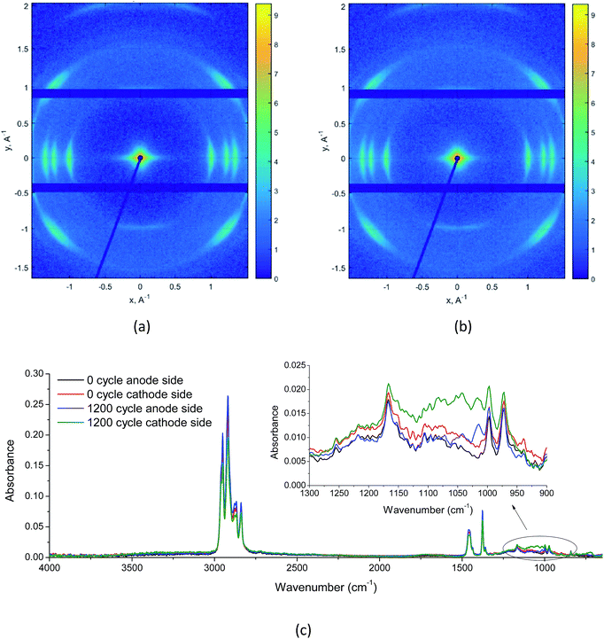 | ||
| Fig. 7 (a) Wide angle XRD images of separator with 0 cycle, (b) wide angle XRD images of separator with 1200 cycles, and (c) FTIR spectrum of 0 and 1200 cycled separators. | ||
Conclusions
The current research shows that the mechanical strength of the separator is subject to degradation as the cell cycles. This effect at the separator level translates to a lower strength and displacement limit at cell level. Therefore, structural designs around the battery pack should take into account a factor of safety driven by effects of aging during charge and discharge cycles. Several factors may influence the aging of lithium-ion battery separators, including temperature and mechanical loading hysteresis during charge and discharge cycles, chemical oxidation of polymer film, resistance increase due to accumulated chemical particles in the pores and the effect of electrolyte. Dry processed trilayer separators (PP/PE/PP) from cells with five different charge–discharge cycles were tested under uniaxial and biaxial loading. It was found that the yield properties did not change between separators that have undergone different number of charge and discharge cycles. However, the failure strength under biaxial loading drops significantly for the separator with 1200 cycles. Cross-sectional views of separators indicated that the topology of fragments did not change. Wide angle XRD suggested minimal change in the crystalline structures orientation after 1200 cycles. Therefore, mechanical deformation due to volume changes in charge and discharge cycles may not explain the loss of puncture strength. Additionally, FTIR spectrum suggested that no new chemical bonds were found on the surfaces and chemical aging was not likely to happen. The only noticeable change between the 1200 cycled and fresh separator was the presence of deposited chemical reaction products as particles inside the 1200 cycled separator. Such deposits may create a stress concentration point in the separator that may lead to its earlier failure. Another cause for the faster failure of 1200 cycled separator may be a physical degradation of polymer chains, for example, chain separation. This topic needs additional extensive research and will be subject of future studies.Conflicts of interest
There are no conflicts to declare.Acknowledgements
This work has been supported by MIT Battery Consortium with sponsorship of Daimler, Jaguar-Land Rover, LG Chem, Boston Power, Peugeot, Citroën, and AVL.Notes and references
- V. Agubra and J. Fergus, Lithium Ion Battery Anode Aging Mechanisms, Materials, 2013, 6, 16 CrossRef PubMed
.
- M. Broussely, P. Biensan, F. Bonhomme, P. Blanchard, S. Herreyre and K. Nechev, et al., Main aging mechanisms in Li ion batteries, J. Power Sources, 2005, 146(1–2), 90–96 CrossRef CAS
.
- J. Vetter, P. Novak, M. R. Wagner, C. Veit, K. C. Moller and J. O. Besenhard, et al., Ageing mechanisms in lithium-ion batteries, J. Power Sources, 2005, 147(1–2), 269–281 CrossRef CAS
.
- G. Sarre, P. Blanchard and M. Broussely, Aging of lithium-ion batteries, J. Power Sources, 2004, 127(1–2), 65–71 CrossRef CAS
.
- M. Ebner, F. Marone, M. Stampanoni and V. Wood, Visualization and Quantification of Electrochemical and Mechanical Degradation in Li Ion Batteries, Sceince, 2013, 342, 716–721 CrossRef CAS PubMed
.
- S. Seki, N. Serizawa, K. Takei and S. Tsuzuki, RSC Advances ionic liquid on the control of interfacial, RSC Adv., 2016, 6, 33043–33047 RSC
.
- N. Spinner, L. Zhang and W. E. Mustain, Investigation of metal oxide anode degradation in lithium-ion batteries via identical-location TEM, J. Mater. Chem. A, 2014, 2(6), 1627–1630 CAS
.
- P. Arora and Z. J. Zhang, Battery separators, Chem. Rev., 2004, 104(10), 4419–4462 CrossRef CAS PubMed
.
- X. Zhang, Mechanical Behavior of Shell Casing and Separator of Lithium-ion Battery, Massachusetts Institute of Technology, 2017 Search PubMed
.
- E. Sahraei, R. Hill and T. Wierzbicki, Calibration and finite element simulation of pouch lithium-ion batteries for mechanical integrity, J. Power Sources, 2012, 201, 307–321 CrossRef CAS
.
- E. Sahraei, M. Kahn, J. Meier and T. Wierzbicki, Modelling of cracks developed in lithium-ion cells under mechanical loading, RSC Adv., 2015, 5, 80369–80380 RSC
.
- E. Sahraei, E. Bosco, B. Dixon and B. Lai, Microscale failure mechanisms leading to internal short circuit in Li-ion batteries under complex loading scenarios, J. Power Sources, 2016, 319, 56–65 CrossRef CAS
.
- X. Zhang, E. Sahraei and K. Wang, Deformation and failure characteristics of four types of lithium-ion battery separators, J. Power Sources, 2016, 327, 693–701 CrossRef CAS
.
- X. Zhang and T. Wierzbicki, Characterization of plasticity and fracture of shell casing of lithium-ion cylindrical battery, J. Power Sources, 2015, 280, 47–56, DOI:10.1016/j.jpowsour.2015.01.077
.
- X. Zhang, E. Sahraei and K. Wang, Li-ion Battery Separators, Mechanical Integrity and Failure Mechanisms Leading to Soft and Hard Internal Shorts, Sci. Rep., 2016, 32578 CrossRef CAS PubMed
.
- K. Yuzawa, Y. Yang, N. Bhandari, M. Sugiyama and S. Nakamura, Automobiles Charging the future: Asia leads drive to next-generation EV battery market, 2016 Search PubMed
.
- A. Sheidaei, X. Xiao, X. Huang and J. Hitt, Mechanical behavior of a battery separator in electrolyte solutions, J. Power Sources, 2011, 196(20), 8728–8734 CrossRef CAS
.
- M. F. Lagadec, M. Ebner, R. Zahn and V. Wood, Communication—Technique for Visualization and Quantification of Lithium-Ion Battery Separator Microstructure, J. Electrochem. Soc., 2016, 163(6), A992–A994 CrossRef CAS
.
- T. Vu-Khanh and M. El Majdoubi, Entropy change with yielding and fracture of polypropylene, Theor. Appl. Fract. Mech., 2009, 51(2), 111–116 CrossRef CAS
.
- J. M. Hutchinson, S. Smith, B. Horne and G. M. Gourlay, Physical aging of polycarbonate: enthalpy relaxation, creep response, and yielding behavior, Macromolecules, 1999, 32(15), 5046–5061 CrossRef CAS
.
| This journal is © The Royal Society of Chemistry 2017 |

