 Open Access Article
Synthesis of core–shell SAPO-34@SAPO-18 composites by the epitaxial growth method and their catalytic properties for the MTO reaction†
Zhiqiang Xu ,
Jianwen Li,
Weixin Qian,
Hongfang Ma,
Haitao Zhang and
Weiyong Ying*
Engineering Research Center of Large Scale Reactor Engineering and Technology, Ministry of Education, State Key Laboratory of Chemical Engineering, East China University of Science and Technology, Shanghai 200237, China. E-mail: wying@ecust.edu.cn; Fax: +86 21 64252192; Tel: +86 21 64252151
First published on 1st December 2017
Abstract
Core–shell SAPO-34@SAPO-18 composites possessing SAPO-34 single-crystal cores and SAPO-18 polycrystalline shells were synthesized by the epitaxial growth method. The core–shell SAPO-34@SAPO-18 composites have been characterized by XRD, SEM, TEM, N2 physisorption, solid state NMR, and NH3-TPD. Finally, their methanol-to-olefin (MTO) catalytic activity was evaluated at 425 °C, and coking behavior was investigated using a Thermax700 thermo-gravimetric analysis (TGA) instrument. The formation of SAPO-18 shell layers was affected by the crystal size, the surface roughness of core SAPO-34, and the silica content of SAPO-18 colloidal solutions. The core–shell SAPO-34@SAPO-18 composites exhibit better catalytic performance for the MTO reaction with over two times prolonged catalytic lifetime and nearly 9% improvement of selectivity to ethylene and propylene compared to the original core SAPO-34. The coke content of the core–shell catalyst distinctly increases to 22% from 19%, showing better utilization of the internal cage after decoration of the shell layer. The enhanced catalytic performance may originate from the passivation of strong acid sites on the external surface of core SAPO-34 by SAPO-18 shell layers.
1. Introduction
Silicoaluminophosphate (SAPO) molecular sieves, an important class of crystalline materials possessing intrinsic cavities and channels, are widely used in separation and catalysis.1–3 A variety of SAPO molecular sieves with characteristic structures have been successfully synthesized since their first invention by the Union Carbide Corporation in the 1980s.4Among the various SAPOs, SAPO-34 with a CHA structure, small pores (0.38 nm), and relatively moderate acid strength shows excellent catalytic properties in MTO reactions and high selectivity to light olefins (above 80%), and 100% methanol conversation can be achieved, attracting considerable attention.5–10 According to hydrocarbon pool mechanism,11 carbon species (typical aromatics, such as methylbenzenes and naphthalene) confined in large CHA cages together with Brønsted acid convert methanol to light olefins. Narrow pore openings allow only small molecules such as light olefins get through, which makes high selectivity to light olefins of SAPO-34. Nevertheless, the carbon species becoming larger aromatic compounds, such as phenanthrene and pyrene during the MTO process, occupy the entire cage, leading to the rapid deactivation and short lifetime of SAPO-34.11–13
The mass transfer of methanol in SAPO-34 crystals was limited by its small cages. Methylbenzene forms rapidly at the corner and edges of catalyst crystals, resulting in only some cages near the external surface were active in MTO reaction, and the internal cages are not entirely used.10 It has been estimated that less 10% cages containing methylbenzenes were active in MTO reaction.12 On the basis of Si incorporation mechanism,13 the outer surface of SAPO-34 synthesized by conventional method possesses stronger acidity compared to inside because of the Si substitution process,14 which could aggravate coke deposition on catalyst outer surface. Gao et al. found that reducing Si content especially the Si content on the SAPO-34 external surface can suppress propylene hydrogenation to propane and enhance the utilization of internal pore space.15 Various approaches have been developed to improve SAPO-34 catalytic properties, such as modifying the catalyst acidity,16,17 optimizing the synthesis conditions,18 decreasing the crystal size,19,20 and the introduction of meso-or/and macropores.21,22 However, there is a rare report about the method which can weaken or passivate SAPO-34 acidity on outer side surface directly.
And for all we know, zeolites external functional group can be modified by a passivating agent such as metal oxides and hydride with chemical vapor deposition (CVD) or chemical liquid deposition (CLD) techniques. However, these ways inevitably cause pore blockage and the increase of diffusion resistance.23 Epitaxial zeolite shell on the surface of a zeolite core with identical or analogous structure can avoid the side effect. Core–shell zeolite composites are comprised of a single zeolite crystal surrounded by a polycrystalline shell of another zeolite phase.24 In recent years, a wide range of core–shell molecular sieve composites such as ZSM-5/silicate-1,23,25 MOR/MFI,26 SOD/CHA,27 silicate-1/ZSM-5 (ref. 28 and 29) has been successfully synthesized. These materials can be prepared by epitaxial growth method (heterogeneous nucleation and growth of the shell on the core) or secondary growth method (nanocrystalline seeds that are first deposited on the core surface and then transformed into a contiguous layer). Some of them showed remarkable applications in catalysis. For example, core–shell composites HZSM-5@SBA-15 (ref. 30) have been synthesized successfully and employed as a catalyst for methanol to propylene (MTP) conversion, and shows higher propylene to ethylene ratio and higher methanol conversion. Vanvu et al. coated H-ZSM-5 with polycrystalline silicate crystals and the silicate coating significantly enhanced para-xylene selectivity up to 99.9%.25 Ghorbanpour et al. prepared core–shell particles consisting of an aluminosilicate core (ZSM-5) and a siliceous shell (silicate-1) by epitaxial growth method. The epitaxial shell can passivate the Brønsted acid sites, and enhance the product selectivity without sacrificing catalyst activity.23
Herein, we intend to use epitaxial growth method to create a nano-sized shell layer to passivate the strong acid sites on the SAPO-34 outside surface and concentrate on the formation of CHA@AEI core–shell zeolite composites comprised of a SAPO-34 core and a polycrystalline SAPO-18 shell. SAPO-18 is also a potential alternative MTO catalyst and was shown to have an improved lifetime due to the lower density and lower strength of acid sites.31,32 SAPO-18 has the AEI framework topology, which is highly similar to CHA, and its eight-membered pore openings are the same as SAPO-34.33–35 SAPO-34 and SAPO-18 can form intergrowth, and Smith et al. studied its crystal-growth mechanism.36 Since the sufficient compatibility between AEI and CHA structure, epitaxial growth of SAPO-18 on the surface of SAPO-34 is possible. SAPOs is composed of Al, P, Si elements and its crystallization mechanism9,37,38 is complicated. The formation of mixed SAPOs shell layer is usually more difficult than silica zeolites, and few people study it. We explored the synthesis conditions of core–shell SAPO-34@SAPO-18 composites including the crystal size, the surface roughness of core SAPO-34 and the silica content of the SAPO-18 colloidal solution. An integrated SAPO-18 polycrystalline shell formed on the SAPO-34 outer layer successfully. SAPO-34@SAPO-18 composites show higher olefins selectivity and longer lifetime compared to original core SAPO-34 in MTO reaction.
2. Experimental
2.1. Catalyst preparation
![[thin space (1/6-em)]](https://www.rsc.org/images/entities/char_2009.gif) :
:![[thin space (1/6-em)]](https://www.rsc.org/images/entities/char_2009.gif) 30. Parts of core samples before addition to the solution were pretreated with TEAOH aqueous solution (1.5% wt) at 80 °C for 10 h. The mixtures were transferred into Teflon-lined stainless steel autoclaves, which were rotated for 30 min and heated at 160 °C for 10 h under rotation. After separation by centrifugation and washing with water, the resultant product was dried at 110 °C for 10 h and calcined at 550 °C for 8 h. The synthesis conditions of samples are summarized in Table 1. Core–shell samples are denoted as C(p)@xS, where C is filled with core sample name LS or SS; the presence of p shows that the core SAPO-34 had been pretreated; S represents shell, and x is consistent with the SiO2/Al2O3 molar ratio in SAPO-18 precursor solutions. In case of SSp@0.15S, the sample was prepared by sample SS after pretreatment and the SAPO-18 precursor solutions of which the SiO2/Al2O3 molar ratio is 0.15.
30. Parts of core samples before addition to the solution were pretreated with TEAOH aqueous solution (1.5% wt) at 80 °C for 10 h. The mixtures were transferred into Teflon-lined stainless steel autoclaves, which were rotated for 30 min and heated at 160 °C for 10 h under rotation. After separation by centrifugation and washing with water, the resultant product was dried at 110 °C for 10 h and calcined at 550 °C for 8 h. The synthesis conditions of samples are summarized in Table 1. Core–shell samples are denoted as C(p)@xS, where C is filled with core sample name LS or SS; the presence of p shows that the core SAPO-34 had been pretreated; S represents shell, and x is consistent with the SiO2/Al2O3 molar ratio in SAPO-18 precursor solutions. In case of SSp@0.15S, the sample was prepared by sample SS after pretreatment and the SAPO-18 precursor solutions of which the SiO2/Al2O3 molar ratio is 0.15.
| Sample | SAPO-34 | SAPO-18 | Mass increase rate (%) | Molar composition (EDS)c | |
|---|---|---|---|---|---|
| SDA | Pretreatmenta | xSiO2b | |||
| a The pretreatment condition was distinguished by Y and N, Y denoted as the pretreatment was carried out; N denoted as not.b Si content in SAPO-18 colloidal solution.c Determined by an energy-diffusive X-ray spectroscope (EDS) analysis. | |||||
| LS | TEA | N | — | — | Al0.47Si0.10P0.42O2 |
| LSp@0S | TEA | Y | 0 | 12.5 | Al0.47Si0.10P0.43O2 |
| LS@0.15S | TEA | N | 0.15 | 32.1 | Al0.48Si0.08P0.44O2 |
| LSp@0.15S | TEA | Y | 0.15 | 34.4 | Al0.47Si0.08P0.45O2 |
| LSp@0.3S | TEA | Y | 0.3 | 47.2 | Al0.47Si0.10P0.43O2 |
| SS | TEAOH | N | — | — | Al0.47Si0.16P0.37O2 |
| SSp@0S | TEAOH | Y | 0 | 28.1 | Al0.48Si0.15P0.37O2 |
| SSp@0.15S | TEAOH | Y | 0.15 | 46.9 | Al0.48Si0.12P0.40O2 |
| SSp@0.3S | TEAOH | Y | 0.3 | 53.1 | Al0.50Si0.12P0.38O2 |
| SAPO-18 | — | — | 0.15 | — | Al0.47Si0.08P0.45O2 |
| MM | TEAOH | — | 0.15 | — | Al0.47Si0.15P0.38O2 |
The mass increase rate of samples was calculated by the following formula: mass increase rate = (M2 − M1)/M1, where M1 and M2 are the total weight of added SAPO-34 cores and the total weight of recovered core–shell particles after filtration and drying, respectively.
2.2. Characterization
The XRD patterns were recorded on a D8 advance X-ray diffractometer using Cu Kα radiations in the range of 2θ = 3–50°. The elemental composition of samples was determined using an energy dispersive spectrometer (EDS TEAMEDS). Nitrogen adsorption–desorption measurements were carried out at −196 °C on Micromeritics ASAP 2020M analyzer, after the samples were degassed at 350 °C for 6 h. Crystal morphology, size and particle size distribution were assessed by scanning electron microscopy (SEM JSM-6360LV); field emission scanning electron microscopy (FESEM Nova NanoSEM 450) and transmission electron microscope (TEM JEM-1400). NH3-TPD was performed on Micromeritics AutoChemII 2920. Typically, 200 mg of samples was pretreated at 550 °C for 2 h in He flow (40 ml min−1) and subsequently cooled to adsorption temperature of 100 °C. After contact of the sample to remove weakly adsorbed NH3 molecules for 60 min. Finally, the He flow (40 ml min−1) was passed through the sample with increasing temperatures up to 650 °C at the rate of 10 °C min−1. 29Si MAS NMR spectra were recorded with a 4 mm MAS probe with a spinning rate of 4 kHz using high-power proton decoupling. 2500 scans were accumulated with a p/4 pulse width of 2.5 ms and a 5 s recycle delay.2.3. Catalytic reaction
The MTO reaction was carried out in a fixed bed at 425 °C under atmospheric pressure. 500 mg sample (40–60 mesh) was packed on the quartz wool plugging inside the stainless steel reactor (i.d: 0.9 cm, length: 65 cm). Pure methanol was fed into pre-heater kept at 200 °C with a flow rate of 0.01 ml min−1 by an advection pump (2PB00C, Beijing Satellite Manufacturing Factory, China). Nitrogen used as an inert diluents gas was co-fed with methanol into pre-heater at 20 ml min−1. The space velocity in WHSV was kept to 1 h−1. The analysis of the reaction product was performed on online chromatographs: Agilent GC 6890N equipped with a flame ionization detector (FID) and a plot-Q column.The coke formation of as-synthesized samples was investigated in Thermax700 thermo-gravimetric analysis (TGA) instrument at 425 °C under atmospheric pressure. The introduction of TGA reactor was reported in our previous work.40 250 mg of samples (40–60 mesh) are loaded at the bottom of bronze sample basket. Methanol feed was injected into reaction system from the constant flux pump at the flow rate of 0.02 ml min−1, with nitrogen as diluent at 40 ml min−1, and methanol partial pressure was approximately 21.7 kPa. The change of catalyst weight can be recorded in situ precisely, with a 0.5 s record frequency.
3. Results and discussion
3.1. Characterization of core–shell SAPO-34@SAPO-18 composites samples
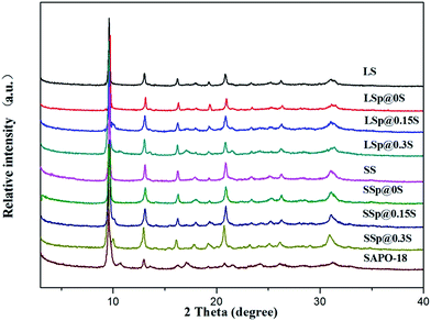
As can be seen from Table 1, the mass increase rate of core–shell composites raised with the increase of silica concentration of SAPO-18 gel. The surface molar composition was investigated by EDS. Though EDS analysis cannot give the quantitative result, it shows that the silica content of core–shell composites samples is lower than the original core crystals. This could be aroused by that the SAPO-34 crystals were coated by low-silica SAPO-18 layers. It is noted that the surface silica content of SSp@0S and LSp@0S were not significantly declined. This phenomenon was probably caused by the low coverage of SAPO-18 due to extremely low silica content in SAPO-18 colloidal solution.XRD patterns of samples are shown in Fig. 1. Sample LS and SS show the typical diffraction peaks of the CHA structures, and sample SAPO-18 which was prepared by precursor solutions without adding SAPO-34 matches very well with the XRD pattern of the AEI-type molecular sieve. Most core–shell composites samples did not show apparent diffraction peaks due to AEI structure except LSp@0.3S. It was supposed to be the SAPO-18 shell layers are too thin to provide diffraction patterns with accurate relative intensities using a conventional diffractometer.41 We collect the detached SAPO-18 shell by centrifugation from sample SSp@0.3S after ultrasonic treatment by 0.05 mol l−1 ammonia solution for 1 h. The characteristic diffraction peaks of AEI appeared in the XRD pattern of the detached shell (Fig. S1†). The diffraction peaks around 2θ = 17.1 and 21.5 due to the SAPO-18 in the LSp@0.3S XRD pattern could be caused by the agglomeration of dissociate SAPO-18 particles. The agglomeration with large size could present stronger diffractions of AEI structure compared with thin shell layers.
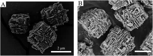
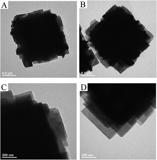
SEM was used to determine the morphology of the materials and the results were shown in Fig. 2. It is immediately clear that there is a significant change in surface morphology between the core–shell composites and original SAPO-34 crystals. The core sample LS (Fig. 2A1) and SS (Fig. 2B1) exhibit a cubical morphology with flat and smooth external faces although their crystal sizes are different (the pristine LS presented crystals of 5–10 μm, and SS presented crystals of 1–4 μm). After epitaxial growth in the clear precursor solution of SAPO-18, a shell layer composed of nano-sized, flaky grains could be observed. The surface crystals are consistent with the morphology of SAPO-18 (Fig. S2†) synthesized by the precursor solution without adding SAPO-34. Besides, the dissociative sheet-like SAPO-18 crystals were visible in core–shell samples with LS cores. It indicates that the homogeneous nucleation of SAPO-18 occurred in the epitaxial growth period. The phenomenon is evident in the sample LSp@0.3S (Fig. S2†), and the SAPO-18 agglomeration could be observed. The result is concomitant with the XRD pattern. Comparing LSp@0.15S (Fig. 2A3) with LS@0.15S, we found that the pretreatment could reduce the dissociative SAPO-18 particles and improve the degree of SAPO-18 coverage. This observation is similar to the results of Brent et al. in which they found that the rougher the original surface of K-LTL, the greater the coverage of Ba-LTL crystals.42 In the core–shell samples with LS cores, the nano-sized SAPO-18 plate-like crystals were overlaid like fish scales on the surface of cube-like SAPO-34 cores. However, they were oriented randomly in the samples SSp@0.15S (Fig. 2B2) and SSp@0.3S (Fig. 2B3). Meanwhile, the dissociate SAPO-18 crystals decrease naturally. As shown in Fig. 3A, the nano-sized SAPO-18 particles distributed sporadically on the surface of SS cores in the SSp@0S. It appeared an integrated core–shell structure cannot be formed when colloidal solutions for epitaxial growth without Si content. The TEM images (Fig. 4) also confirmed the core–shell structure of SSp@.15S. A thin polycrystalline SAPO-18 shell wraps the SS core completely. The shell thickness is around 250 nm, which is approximately equal to the size of an individual plate-like SAPO-18 particle.
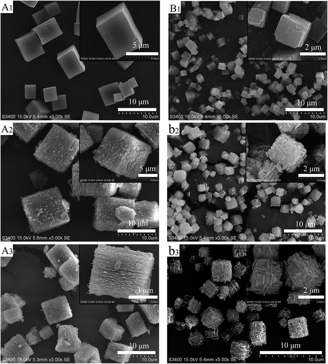 | ||
| Fig. 2 SEM images of LS (A1), LS@0.15S (A2), LSp@0.15S (A3), SS (B1), SSp@0.15S (B2), SSp@0.3S (B3). | ||
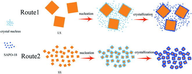
By our findings, the proposed process for the formation of core–shell SAPO-34@SAPO-18 composites is shown in Scheme 1. With heating of clear SAPO-18 colloidal solution, the dissolved Al-, P-, and Si-sources start to react and form precursor species. The defects on the SAPO-34 surface become the anchor points of SAPO-18 precursor species. Simultaneously, the precursor species nucleate and then crystallize by addition of nutrients from the synthesis solution. Finally, SAPO-18 polycrystalline shell layers form on the surface of SAPO-34 cores. During epitaxial growth, there are two competing types of SAPO-18 nucleation: heterogeneous and homogeneous. Compared two routes in Scheme 1, it can be concluded that the improvement of the surface roughness and the decrease of core crystal size benefit heterogeneous nucleation. Heterogeneous nucleation drives the SAPO-18 particles to grow on the core surface, and a better core–shell structure can be achieved. Small crystal size could bridge the distance between crystal nucleus and make SAPO-18 grow interactively, which creates more compact shell layers. Si content in the precursor solution can affect the quantity of crystal nucleus and growth speed of SAPO-18. Nano-sized SAPO-18 particles are incapable of clustering to coat cores entirely when Si content in the precursor solution is extremely low. Smith et al. probed the growth mechanism of the SAPO-34/SAPO-18 intergrowth materials and found two competing mechanisms at the surface: layer-by-layer and spiral.36 The intergrowth phase can be formed by layer growth since the (001) surface of SAPO-18 is isostructural with SAPO-34. The structure of the interface between the SAPO-34 core and SAPO-18 shell may be analogous to the intergrowth materials. SAPO-18 shell layers could connect core SAPO-34 in the [001] AEI direction without any blocking.
The textural properties of SAPO-34, SAPO-18, and core–shell composites were determined using N2 adsorption–desorption measurements. The results were shown in Table 2. All of the samples show type-I N2 adsorption/desorption isotherms (Fig. S3†). The uptake near saturation pressure in the isotherms could be observed in the core–shell composites and sample SAPO-18, and these samples exhibited increased external areas and mesopore volume as compared with core samples. The phenomenon most probably related to space filling in grain boundaries or pinholes between small SAPO-18 crystals. Notably, core–shell samples except LSp@0.3S exhibited larger microporous areas than core samples. It indicates that nano-sized SAPO-18 shell did not block outermost pore openings of SS core. The decreased microporous area of LSp@0.3S thanks to the occultation of dissociative SAPO-18 crystals to the pore openings.
| Sample | Surface area (m2 g−1) | Pore volume (cm2 g−1) | |||
|---|---|---|---|---|---|
| SBETa | Smicrob | Sextb | Vmicrob | Vmesoc | |
| a BET surface area.b Smicro (micropore area), Sext (external surface area) and Vmicro (micropore volume) determined from the t-plot method.c Vmeso (mesopore volume) = Vbet − Vmicro; Vbet is determined from the adsorbed volume at P/P0 = 0.98. | |||||
| LS | 540.7 | 535.4 | 5.3 | 0.28 | 0.01 |
| LSp@0S | 560.1 | 546.7 | 13.4 | 0.28 | 0.05 |
| LSp@0.15S | 562.0 | 534.3 | 27.7 | 0.28 | 0.10 |
| LSp@0.3S | 536.8 | 511.5 | 25.3 | 0.26 | 0.10 |
| SS | 483.3 | 472.4 | 10.9 | 0.26 | 0.02 |
| SSp@0S | 516.4 | 488.7 | 27.8 | 0.25 | 0.04 |
| SSp@0.15S | 538.1 | 505.2 | 32.9 | 0.26 | 0.06 |
| SSp@0.3S | 551.0 | 529.9 | 21.1 | 0.27 | 0.03 |
| SAPO-18 | 577.2 | 524.3 | 52.8 | 0.28 | 0.14 |
The acidic properties of the samples were measured by NH3-TPD, and the results were shown in Fig. 5A and S4.† All the samples presented two desorption peaks at 180–230 and 410–480 °C. The former one was attributed to the desorption of physisorbed NH3, and NH3 adsorbed on lattice defects or terminal Si(OH), P(OH) and Al(OH). The latter one mainly arose from NH3 desorption from Brønsted acid sites (the bridged hydroxyl groups Si(OH)Al), which should be active for MTO reaction. Core sample SS exhibits extremely high and broad weak acid peak and the strong acid peak locating at the higher temperature compared to LS, which should be correlated with high SiO2 content in SS initial gel. Abundant silicon incorporated into SAPO-34 created a large number of silica islands.43 In the framework of SAPO-34, the acidic strength of bridge hydroxyl species of Si(nAl) decrease in the order of Si(1Al) > Si(2Al) > Si(3Al) > Si(4Al) > Si(0Al).44 The high and broad weak peak of sample SS might be ascribed to Si(0Al) in the mid of these silica islands. Si(1–3Al) at edges of silica islands increase the strong acid sites strength of sample SS, which causes the higher desorption temperature. The strong and weak acid peaks of core–shell composites are both shifted to lower temperature and exhibit smaller areas compared to core samples, suggesting the decrease of acidity and acid quantity derived from SAPO-18 decoration. The low-silica SAPO-18 shell layer replaced the original external surface containing numerous silica islands, which make an inevitable sacrifice of surface acidity. It is noted that SSp@0.15S possess the weakest acidity among all core–shell composites, which could be corresponded to better core–shell structure and the moderate Si content in the SAPO-18 precursor solution. 29Si MAS NMR was used to investigate the Si environment in the framework of samples SS and SSp@0.15S. The 29Si MAS NMR spectra (Fig. 5B) presents five resonance signals with chemical shift at −89, −94, −100, −105 and −110, corresponding to the coordination states of Si(4Al), Si(3Al), Si(2Al), Si(1Al) and Si(0Al), respectively. Sample SS presents rather intensive peaks at −105 and −110 pm assigned to Si(1Al) and Si(0Al). It implied that a large number of silica islands existed, indicating a good agreement with NH3-TPD results. Sample SSp@0.15S presents weaker peaks at −94, −100, −105 and −110 compared to sample SS, which suggested the decrease of Si(3Al), Si(2Al), Si(1Al), Si(0Al). The different Si distribution that we have observed for sample SSp@0.15S could be attributed to the shell layer.
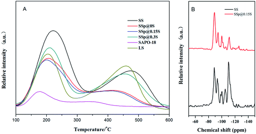 | ||
| Fig. 5 NH3-TPD profiles of samples SS, SSp@0S, SSp@0.15S, SSp@0.3S, LS and SAPO-18 (A); 29Si MAS NMR spectra of sample SS and sample SSp@0.15S (B). | ||
3.2. Catalytic performance in the MTO reaction of SAPO-34@SAPO-18 composites samples
The catalytic properties for MTO reaction of core and core–shell composites samples were tested in a fix-bed reactor. The mechanical mixture denoted as sample MM was prepared by mixing 1.6 g SS with 0.75 g SAPO-18 (mixing ratio was consistent with the mass increase rate of SSp@0.15S). Its catalytic properties were also investigated in MTO reaction to elucidate the effect of core–shell structure on catalytic performance.As shown in Fig. 6, the lifetime (during which >99% methanol conversion can be kept) is the only 250 min for the core sample SS catalyst. Sample SAPO-18 presented the most extended lifetime of 680 min. The obviously prolonged lifespan could be observed over core–shell composites samples, revealing that the catalytic stability could be increased after epitaxial growth of SAPO-18. Sample SSp@0.15S showed a longer lifetime of 580 min compared with sample MM, indicating the significance of the core–shell structure. Complete methanol conversion over sample SSp@0S and SSp@0.3S could be maintained for about 335 min, which was shorter than SSp@0.15S, while samples SSp@0S and SSp@0.3S showed slower deactivation rate and methanol conversion exceeding 95% could be kept for approximately 505 min. To our knowledge, the catalytic stability of acidic zeolites during the MTO process is influenced by multiple factors, such as acidity and crystal size. The superior stability of sample SAPO-18 had the benefit from the low acidity and the small crystal size. A higher acid strength and density do a favor for coke deposition causing a shortened catalyst lifetime. As evidenced by NH3-TPD, core samples possessed stronger acidity compared to core–shell samples. Excessive strong acid sites facilitated the coke formation, which results in rapid blocking of pore channels and openings near the external surface of the catalyst. Eventually, the mass diffusion pathway was inhibited, and the original core samples show inferior catalytic stability. On the one hand, the SAPO-18 shells could passivate the surface acidity of core crystals and decelerated the coking rate near outer layer. On the other hand, the AEI cage possessing larger void volume compared to the CHA cage may do a favor for the mass transfer of methanol and the products. Consequently, the blocking of pore openings near the outer layer was inhibited, and more internal cages could be active, leading to the improved catalytic stability. Sample SSp@0.15S obtained the outstanding catalytic stability among core–shell composites samples result from the integrated SAPO-18 layers with a low acidity. The poorer stability of sample SSp@0S seemed to be caused by incomplete coverage. As to SSp@0.3S, relative high silica content in gel seemingly couldn't passivate surface acidity efficiently, leading to higher coke deposition rate and shorter lifetime.
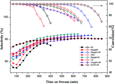 | ||
| Fig. 6 Methanol conversion and selectivity to ethylene plus propylene with time-on-time over as-synthesized samples. Reaction conditions: 425 °C, WHSV = 1 h−1, catalyst weight = 500 mg. | ||
The light olefins (ethylene and propylene) selectivity was shown in Fig. 6. It could be seen that light olefins are the main products for all catalysts. Sample SS displays the lowest selectivity to ethylene plus propylene (maximum of 74.1%), in accordance with it having the short catalytic lifetime. With the decoration of nano-sized SAPO-18 shell, the selectivity to ethylene plus propylene presents an increasing trend, and sample SSp@0.15S exhibits excellent selectivity to ethylene plus propylene (maximum of 83.1%), which are apparently higher than that of core sample SS. The light olefins selectivities of samples SS, MM and SSp@0.3S show a declining trend at the beginning of the MTO reaction, which is resulted from hydrogen transfer reaction of propylene to propane. The hydrogen transfer index (HTI, C3H8/C3H6) of samples was shown in Fig. S7.† The HTI values over samples SSp@0.15S and SSp@0S start from 0.23 which are much lower than that over samples SS, MM and SSp@0.3S, and remain equable in the initial period of MTO reaction. The reduction of strong acid sites by the epitaxial growth in a low-silica SAPO-18 precursor solution could depress propane formation. As a result, core–shell composites samples exhibited better initial selectivity to ethylene plus propylene compared with core samples. On the contrary, without the epitaxial growth, disperse SAPO-18 particles couldn't tune external surface acidity, and the HTI value still kept high in the initiation of the MTO reaction over sample MM. Sample SSp@0.3S presents a higher selectivity to light olefins compared to sample SSp@0.15S after 108 min of TOS despite high HTI value in the initial period. According to NH3-TPD and the selectivity to heavy products (Fig. S4†), we implied that surplus strong acid sites in sample SSp@0.3S promote the formation of polycyclic aromatic hydrocarbons which occupy the cages restraining heavy products generation and diffusion. As a result, sample SSp@0.3S possessed shorter lifetime and higher light olefins selectivity. The stability of our core–shell composites sample SSp@0.15S was further tested by a reaction–reactivation cycling. As shown in Fig. S8,† the lifetime and selectivity of ethylene plus propylene are quite stable during four times cycling.
By use of Thermax700 TGA reactor, the coke formation processes of samples SS, SSp@0.15S, MM, LS, LSp@0.15S were recorded in situ. The dehydration of samples during the heating process has been observed by TGA instrument. AS shown in Fig. S9,† the dehydration amount is roughly 23.5% (wt%) in every circumstance. Dehydrated weight is used for the calculation of WHSV in the study of coke deposition behaviors. As depicted in Fig. 7, the weight of catalyst increased soon after methanol injection. The weight increasing rate slowed down, and TGA curve turned into the flat with reaction time. It can be seen that sample SS has larger coke content than sample LS, which is contributed to the smaller crystallite size. Sample SSp@0.15S shows a larger capacity for coke species and a slower coking formation rate compared to sample SS. The low-silica SAPO-18 shell layer with low acid sites inhibited coking and blocking of the pore openings. The larger void volume of AEI cage compared to CHA cage (1450 Å3 compared to 1110 Å3) could reduce the diffusion resistance in the outer layer of catalyst particles. The mass transfer is improved, and the internal cages are better utilized. Conversely, the finally steady coke content of sample MM decreased to 15%, which is probably attributed to that dissociative SAPO-18 particles blocked SAPO-34 pore opening during pelleting. The TGA results demonstrate the positive function of nano-sized SAPO-18 shell layer formed by epitaxial growth method for better utilization of internal pore space.
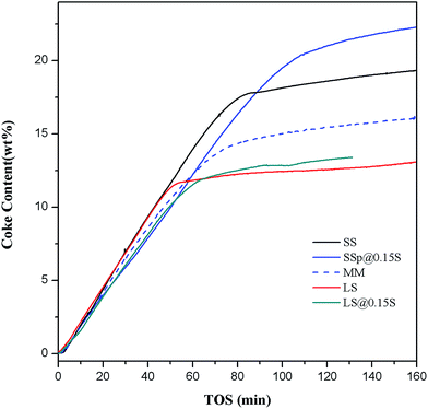 | ||
| Fig. 7 Coke formation for samples SS, SSp@0.15S, MM, LS, LSp@0.15S. Reaction conditions: 425 °C, WHSV = 5.56 h−1, catalyst weight = 500 mg. | ||
4. Conclusions
SAPO-34 crystals were coated with low-silica SAPO-18 ploycrystallites shells of about 250 nm thickness by epitaxial growth method. Core crystalline size, Si content in SAPO-18 clear precursor solution and pretreatment is revealed to be crucial to the shell layers formation. Improving the surface roughness and decreasing the crystal size could supply more anchorage points for the heterogeneous nucleation and epitaxial growth of SAPO-18. Excessive low silica content in the SAPO-18 precursor solution goes against SAPO-18 growth, leading to the low coverage of SAPO-18.Core–shell SAPO-34@SAPO-18 composites showed enhanced catalytic performance including longer catalytic lifetime and higher selectivity towards light olefins compared to original core SAPO-34. The low-silica SAPO-18 shell layer can weaken the strong acid sites of SAPO-34. It can efficiently depress hydrogen transfer reaction of propylene to propane. The larger void volume of AEI cage compared to CHA cage and low coking deposition rate of SAPO-18 may improve the mass transfer of methanol and products. Eventually, core–shell composites show an improved capacity for coke species.
Conflicts of interest
There are no conflicts to declare.Acknowledgements
We gratefully acknowledge the financial supports of the National Key Technology Research Program of China (No. 2006BAE02B02) and the Fundamental Research Funds for the Central Universities (No. 222201717013).Notes and references
- J. Shi, Y. Wang, W. Yang, Y. Tang and Z. Xie, Chem. Soc. Rev., 2015, 44, 8877–8903 RSC.
- M. E. Davis, Nature, 2002, 417, 813–821 CrossRef CAS PubMed.
- Z. Wang, J. Yu and R. Xu, Chem. Soc. Rev., 2012, 41, 1729–1741 RSC.
- S. T. Wilson, B. M. Lok, C. A. Messina, T. R. Cannan and E. M. Flanigen, J. Am. Chem. Soc., 1982, 104, 1146–1147 CrossRef CAS.
- Z. Li, J. Martinez-Triguero, P. Concepcion, J. Yu and A. Corma, Phys. Chem. Chem. Phys., 2013, 15, 14670–14680 RSC.
- P. Wang, A. Lv, J. Hu, J. a. Xu and G. Lu, Microporous Mesoporous Mater., 2012, 152, 178–184 CrossRef CAS.
- D. Fan, P. Tian, S. Xu, Q. Xia, X. Su, L. Zhang, Y. Zhang, Y. He and Z. Liu, J. Mater. Chem., 2012, 22, 6568 RSC.
- T. Álvaro-Muñoz, C. Márquez-Álvarez and E. Sastre, Catal. Today, 2012, 179, 27–34 CrossRef.
- L. Zhang, J. Bates, D. Chen, H.-Y. Nie and Y. Huang, J. Phys. Chem. C, 2011, 115, 22309–22319 CAS.
- N. Nishiyama, M. Kawaguchi, Y. Hirota, D. Van Vu, Y. Egashira and K. Ueyama, Appl. Catal., A, 2009, 362, 193–199 CrossRef CAS.
- J. F. Haw, W. Song, D. M. Marcus and J. B. Nicholas, Acc. Chem. Res., 2003, 36, 317–326 CrossRef CAS PubMed.
- B. P. C. Hereijgers, F. Bleken, M. H. Nilsen, S. Svelle, K.-P. Lillerud, M. Bjørgen, B. M. Weckhuysen and U. Olsbye, J. Catal., 2009, 264, 77–87 CrossRef CAS.
- J. Tan, Z. Liu, X. Bao, X. Liu, X. Han, C. He and R. Zhai, Microporous Mesoporous Mater., 2002, 53, 97–108 CrossRef CAS.
- G. Liu, P. Tian, Y. Zhang, J. Li, L. Xu, S. Meng and Z. Liu, Microporous Mesoporous Mater., 2008, 114, 416–423 CrossRef CAS.
- B. Gao, M. Yang, Y. Qiao, J. Li, X. Xiang, P. Wu, Y. Wei, S. Xu, P. Tian and Z. Liu, Catal. Sci. Technol., 2016, 6, 7569–7578 CAS.
- M. Kang, M.-H. Um and J.-Y. Park, J. Mol. Catal. A: Chem., 1999, 150, 195–203 CrossRef CAS.
- T. Inui and M. Kang, Appl. Catal., A, 1997, 164, 211–223 CrossRef CAS.
- S. Lin, J. Li, R. P. Sharma, J. Yu and R. Xu, Top. Catal., 2010, 53, 1304–1310 CrossRef CAS.
- S. Askari, A. Bashardoust Siahmard, R. Halladj and S. Miar Alipour, Powder Technol., 2016, 301, 268–287 CrossRef CAS.
- G. Yang, Y. Wei, S. Xu, J. Chen, J. Li, Z. Liu, J. Yu and R. Xu, J. Phys. Chem. C, 2013, 117, 8214–8222 CAS.
- X. Chen, D. Xi, Q. Sun, N. Wang, Z. Dai, D. Fan, V. Valtchev and J. Yu, Microporous Mesoporous Mater., 2016, 234, 401–408 CrossRef CAS.
- Q. Sun, N. Wang, D. Xi, M. Yang and J. Yu, Chem. Commun., 2014, 50, 6502–6505 RSC.
- A. Ghorbanpour, A. Gumidyala, L. C. Grabow, S. P. Crossley and J. D. Rimer, ACS Nano, 2015, 9, 4006–4016 CrossRef CAS PubMed.
- Y. Bouizi, L. Rouleau and V. P. Valtchev, Chem. Mater., 2006, 18, 4959–4966 CrossRef CAS.
- D. Vanvu, M. Miyamoto, N. Nishiyama, Y. Egashira and K. Ueyama, J. Catal., 2006, 243, 389–394 CrossRef.
- Y. Bouizi, L. Rouleau and V. P. Valtchev, Microporous Mesoporous Mater., 2006, 91, 70–77 CrossRef CAS.
- T. Wakihara, S. Yamakita, K. Iezumi and T. Okubo, J. Am. Chem. Soc., 2003, 125, 12388–12389 CrossRef CAS PubMed.
- D. V. Vu, M. Miyamoto, N. Nishiyama, S. Ichikawa, Y. Egashira and K. Ueyama, Microporous Mesoporous Mater., 2008, 115, 106–112 CrossRef CAS.
- L. Gora, B. Sulikowski and E. M. Serwicka, Appl. Catal., A, 2007, 325, 316–321 CrossRef CAS.
- X. Qian, J. Du, B. Li, M. Si, Y. Yang, Y. Hu, G. Niu, Y. Zhang, H. Xu, B. Tu, Y. Tang and D. Zhao, Chem. Sci., 2011, 2, 2006 RSC.
- R. Martínez-Franco, Z. Li, J. Martínez-Triguero, M. Moliner and A. Corma, Catal. Sci. Technol., 2016, 6, 2796–2806 Search PubMed.
- Y. Hirota, M. Yamada, Y. Uchida, Y. Sakamoto, T. Yokoi and N. Nishiyama, Microporous Mesoporous Mater., 2016, 232, 65–69 CrossRef CAS.
- R. L. Smith, S. Svelle, P. del Campo, T. Fuglerud, B. Arstad, A. Lind, S. Chavan, M. P. Attfield, D. Akporiaye and M. W. Anderson, Appl. Catal., A, 2015, 505, 1–7 CrossRef CAS.
- D. M. Marcus, W. Song, L. L. Ng and J. F. Haw, Langmuir, 2002, 18, 8386–8391 CrossRef CAS.
- W. A. Sławiński, D. S. Wragg, D. Akporiaye and H. Fjellvåg, Microporous Mesoporous Mater., 2014, 195, 311–318 CrossRef.
- R. L. Smith, W. A. Sławiński, A. Lind, D. S. Wragg, J. H. Cavka, B. Arstad, H. Fjellvåg, M. P. Attfield, D. Akporiaye and M. W. Anderson, Chem. Mater., 2015, 27, 4205–4215 CrossRef CAS.
- B. Gao, D. Fan, L. Sun, H. An, F. Fan, S. Xu, P. Tian and Z. Liu, Microporous Mesoporous Mater., 2017, 248, 204–213 CrossRef CAS.
- T. Wang, X. Lu and Y. Yan, Microporous Mesoporous Mater., 2013, 168, 155–163 CrossRef CAS.
- H. van Heyden, S. Mintova and T. Bein, Chem. Mater., 2008, 20, 2956–2963 CrossRef CAS.
- H. Hu, F. Cao, W. Ying, Q. Sun and D. Fang, Chem. Eng. J., 2010, 160, 770–778 CrossRef CAS.
- M. Razavian and S. Fatemi, Microporous Mesoporous Mater., 2015, 201, 176–189 CrossRef CAS.
- R. Brent, S. M. Stevens, O. Terasaki and M. W. Anderson, Cryst. Growth Des., 2010, 10, 5182–5186 CAS.
- L. Xu, A. Du, Y. Wei, Y. Wang, Z. Yu, Y. He, X. Zhang and Z. Liu, Microporous Mesoporous Mater., 2008, 115, 332–337 CrossRef CAS.
- G. A. V. Martins, G. Berlier, S. Coluccia, H. O. Pastore, G. B. Superti, G. Gatti and L. Marchese, J. Phys. Chem. C, 2007, 111, 330–339 CAS.
Footnote |
| † Electronic supplementary information (ESI) available. See DOI: 10.1039/c7ra11395a |
| This journal is © The Royal Society of Chemistry 2017 |

