 Open Access Article
Research on influencing factors and its optimization of metal powder injection molding without mold via an innovative 3D printing method
Xiaokang Yan,
Liang Hao *,
Wei Xiong and
Danna Tang
Advanced Manufacturing Research Center for Jewelry, Gemological Institute, China University of Geosciences, Wuhan, 430074, China. E-mail: haoliang4883@outlook.com; Fax: +86 27 87482950; Tel: +86 27 67884883
First published on 5th December 2017
Abstract
Using laboratory-made three-dimensional (3D) printing equipment, an innovative 3D printing process without a mold, which was based on metal powder injection molding (MIM), was developed for the fabrication of complex 3D metal and alloy components. Copper powder and paraffin wax were selected for the composition of the copper paste composite. The study was performed to analyse the effects of printing process parameters on the layer-by-layer injection and forming mechanism of the copper paste. Furthermore, the effects of heating parameters during the sintering process on the microstructure and some physical properties of the samples were investigated. The results revealed that the sintering temperature of the copper paste was initiated at a lower temperature (ca. 300 °C) than that of bulk copper metal. The optimal conditions of the heating process of copper paste were explored. The optimal conditions of the sintering temperature were above 950 °C with a holding time of 120 min. Herein, a metal component was manufactured with a complex 3D structure, dense microstructure, superior metallurgical bonding and a flat surface based on our research. The results of our study demonstrate the potential to manufacture metal and alloy components by means of a low cost 3D printing technique.
1 Introduction
Advanced equipment, unmanned aerial vehicles and artificial satellites, and other high-tech areas following the low energy consumption and miniaturization trend have made small components and structures of 10 μm to 100 mm have a huge market demand. Processing and forming methods based on micro-components have become hot topics.1,2 Metal materials with excellent mechanical properties and processing performance in the field of micro-metal and alloy parts manufacturing have attracted the attention of researchers around the world. Metal powder injection molding (MIM), an established net-shape manufacturing process that combines powder metallurgy with plastic injection molding, is an effective method for manufacturing metal and alloy components.3–5 It capitalizes on the most useful characteristics of powder metallurgy (e.g. low-cost, simplicity, flexibility of composition selection and inexpensive raw materials) and plastic injection molding (e.g. ability to manufacture complex parts and rapid production) to manufacture small-to-medium sized intricate components.6 However, despite the advantages of MIM in the mass production of metals and alloy components, it is not conducive to the personalized manufacturing of components due to it requiring the use of a mold before manufacturing. In addition, the design and use of molds make it difficult for MIM to realize the fabrication of micro-metal parts with complex three-dimensional (3D) structures. Therefore, in order to solve these problems, in this work an innovative 3D printing process without a mold and based on MIM was used for the fabrication of complex 3D metal and alloy components via a copper paste injection printing process and laboratory-made 3D printing equipment.3D printing is an additive manufacturing technology, exhibiting the ability to manufacture metallic components with complex structures and advanced functionality.1,7 A variety of 3D printing methods such as Laser Micro Sintering (LMS), Selective Laser Melting (SLM) and Electron Beam Melting (EBM) have been applied to produce 3D metallic structures.8–10 In this work, an innovative 3D printing technique via metal paste injection 3D printing based on MIM was developed for the fabrication of complex 3D metals and alloys. Metal paste injection 3D printing uses the material deposition principle to form 3D shapes layer-by-layer, similar to Fused Deposition Modeling (FDM),11,12 but it requires a sintering process to remove the adhesive material and consolidate the metallic materials. A specific binder wax material is mixed with fine metal particles to formulate paste composites. These metal pastes can be heated to semi-molten pastes and injected from a fine deposition nozzle. Then the injected material is cooled and solidified layer-by-layer to form 3D shapes. Then the 3D solidified paste part is heated up in the oven to vaporize the binder materials and the remaining metal powders are sintered into a dense metal part, similar to the post-processing used in the MIM process.3,13,14 As using a mold is not required, metal paste injection 3D printing shows a clear advantage over MIM in terms of complex micro-metallic structure fabrication.
Paste injection 3D printing equipment is cost-effective compared to SLM, LMS and EBM equipment, which can also be utilized to print a wide range of materials. However, the main difference between metal paste injection 3D printing and MIM is whether molds are used or not. As a new and emerging technology, it requires further research on basic scientific problems such as the metal paste composition and formulation, interfacial bonding, the dewaxing process and the metal sintering mechanism. In addition, the forming performance control and optimization mechanisms remain to be studied. A recent study reported that N. Kiml et al. used a 3D printer with an extrusion device to deposit a copper powder and polymer paste with high viscosity.15,16 The formed prototype billet could be sintered and post-processed into a 3D metallic structure in their work. Thus, the feasibility of the moldless mold-ability of MIM technology has been initially confirmed, but they did not establish a link between metal paste injection 3D printing and MIM in theory and technically. Besides, there was no systematic discussion of the factors affecting the forming process and the manufactured metal parts had a very large optimization space due to not only the complexity of the 3D structure but also the micro-structure. Therefore, in order to produce metal and alloy components with more complex structures and excellent physical and chemical properties, the main influencing factors of metal paste injection 3D printing must be analyzed and optimized.
In this work, copper particles were utilized to formulate a paste with a paraffin wax adhesive and the composition ratio of the copper paste was briefly discussed. Using laboratory-based metal paste injection 3D printing equipment, preliminary systematic studies on the regularity and mechanism of the forming control and sintering process were carried out.
2 Experiment
2.1 Materials and experimental method
For the paste material formulation, copper powders with an average particle size of 0.5 μm were selected (the purity was >99.5%), the scanning electron microscopy (SEM) image of which is shown in Fig. 1a. It can be seen that the copper powders are spherical and uneven in size so that small particles can be filled into the gaps formed by the accumulation of large particles, increasing the content of the powder, reducing the paste shrinkage volume and improving the density and mechanical properties of the samples after sintering.17,18 Paraffin wax was utilized as a bonding material (density of 0.9 g cm−3, CnH2n+2 (20 < n < 24), and a decomposition temperature of 164.3–315.1 °C).In order to simplify the analysis, it was assumed that the size of all of the copper powder particles was 0.5 μm based on the copper particle size frequency histogram (Fig. 1b) which revealed that 70% of the copper particle size distribution was in the range of 0.4–0.6 μm. The paraffin wax was completely immersed in the powder-forming void (regardless of the interface wetting), so that the mass ratio of powder to paraffin (m1![[thin space (1/6-em)]](https://www.rsc.org/images/entities/char_2009.gif) :
:![[thin space (1/6-em)]](https://www.rsc.org/images/entities/char_2009.gif) m2 = 10
m2 = 10![[thin space (1/6-em)]](https://www.rsc.org/images/entities/char_2009.gif) :
:![[thin space (1/6-em)]](https://www.rsc.org/images/entities/char_2009.gif) 1) was calculated from an idealized model (Fig. 1b), providing a reference for the preparation of the copper paste.
1) was calculated from an idealized model (Fig. 1b), providing a reference for the preparation of the copper paste.
Laboratory-based paste injection 3D printing equipment was built for experimental study, and is shown in Fig. 2. The equipment is composed of a 3D movement platform (Fig. 2a) and a syringe with a nozzle aperture of 0.3 mm in diameter (Fig. 2b). The paste was prepared by mixing two materials with a preparation device (Fig. 2c) that agitated and heated up the mixed paste within a temperature range of 50–250 °C. The 3D movement platform was controlled by 3D printing slicing software (Cura 2.1.3). Since the copper powder easily agglomerates, it was sieved using a sieve before the preparation of the copper paste to prevent the plugging phenomenon occurring during the printing process. After the preparation of the copper paste was completed, the syringe was shaken to remove bubbles that might have been present in the paste.
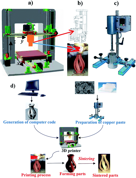 | ||
| Fig. 2 The 3D printing experiment device: (a) a 3D movement platform; (b) a syringe with a nozzle; (c) a metal paste preparation device; (d) the experimental method and process. | ||
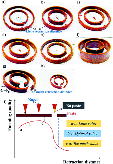
The forming of the component is closely related to the printing parameters. In this study, the main factors affecting the formation that were controlled by Cura 2.1.3 include the extrusion amount (controlled by the drive gear diameter), the single layer height and the retraction distance. The parameters of the single variable method were used to observe the bonding between the layers and the surface quality under different printing conditions, so as to determine the best printing parameters.
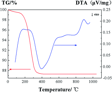
After the printing process, because the surface energy of the small copper powder particles was high and they were easily oxidised, the use of carbon powder could provide a reducing environment in the air atmosphere, and so the deposited copper paste samples were put into a muffle furnace (SX2-5-12, China) under the conditions of carbon powder embedding to explore the sintering process. Besides, due to the capillary force, the carbon powder could improve the liquid mass transfer efficiency of pre-sintering. The microstructure of the samples was observed by a field emission scanning electron microscope (FE-SEM, SU8010, Hitachi, Japan). In order to determine the optimum sintering temperature and holding time, the sample density, hardness, shrinkage and mass sintering loss rate were also measured. The density was measured by a drainage method and the hardness was tested by a digital micro-hardness tester (HVS-1000B). Before the sintering process, thermogravimetric analysis-differential thermal analysis (TG-DTA, STA449F3, Germany) of the copper paste was carried out under a N2 atmosphere with an experimental range of 20–1050 °C and at a heating rate of 5 °C min−1. All of the above processes are summarized in Fig. 2d.
3 Results and discussion
3.1 The effect of printing parameters on the forming quality
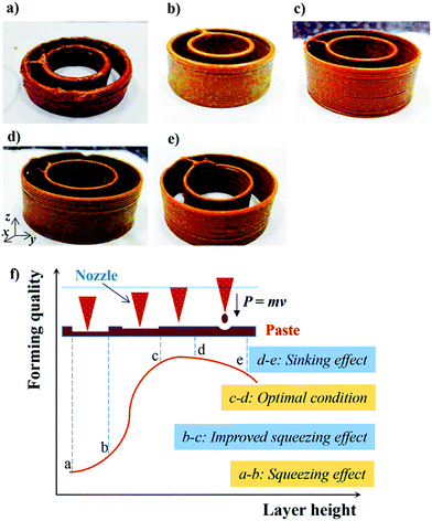
The printing parameters are critical to the manufacturing of the components. Under the conditions of the existing equipment, the complex structures of the 3D components can only be formed under the optimal printing parameters. In this work, in order to obtain the best forming process parameters, the influence of parameters such as the single layer height, retraction distance and extrusion amount on the forming quality and the mechanism was analyzed.Based on the above analysis, the influence mechanism of the single layer height on the forming quality can be summarized as the following four stages (Fig. 3f). When the layer height is too small, because of the “squeeze effect”, the forming quality is poor, corresponding to section a–b in Fig. 3f. With an increase in the single layer height, the forming quality is improved due to the improvement of the “squeeze effect” (section b–c in Fig. 3f) until the best forming effect is obtained (section c–d in Fig. 3f). By further increasing the layer height, the impulse effect of the deposited paste causes a “sinking effect”, leading to worse forming quality again, corresponding to section d–e in Fig. 3f. Obviously, the corresponding single layer height of section c–d in Fig. 3f is optimal.
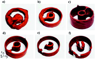
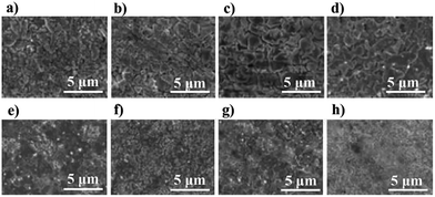
The mechanism of the effect of the drive gear diameter on the forming process is relatively simple compared with that of the line withdrawal value and the single layer height. Samples printed under different conditions of the drive gear diameter are shown in Fig. 5. When the drive gear diameter parameter was at a low level, too much copper paste was injected in the unit time, causing the problem that the sample formed was irregular and paste-like and could not be formed as a 3D shape (Fig. 5a). With an increase in the drive gear diameter parameter, the forming quality was gradually improved (Fig. 5b and c). When the drive gear diameter was set to 7.5 mm, the forming quality was better and the surface was smooth and uniform (Fig. 5d). Further increasing the drive gear diameter parameter caused the forming quality to deteriorate because of the too-small extrusion amount resulting in a gap (Fig. 5e and f).
3.2 Thermodynamic properties of copper paste
After the forming parts are obtained, the sintering process must be carried out to complete the manufacturing of the metal components. The sintering of copper paste is a complicated process, which can be typically divided into two stages: removal of the wax binder and densification of the metal powders. These two stages may not be separated in the sintering process. Prior to the sintering process, the control of the sintering parameters can be guided by thermogravimetric analysis.The TG-DTA curve is shown in Fig. 7. The TG curve shows that the sample exhibited slight weight loss (less than 2%) at 200 °C, indicating that the wax existing on the paste surface started to melt and removal of the wax was initiated. When the temperature increased from 200 to 300 °C, the sample demonstrated severe weight loss (about 10%), implying that the main stage of paraffin decomposition and removal occurred in this heat phase. As the temperature increased from 300 to 400 °C, the sample exhibited slight weight loss, indicating the end of paraffin decomposition. Beyond 400 °C, the sample quality was almost unchanged. The endothermic peak of the DTA curve at 300 °C shows that the sintering process of the copper paste was initiated at a lower temperature. The endothermic peak at 900 °C indicates that the sintering was into the late stage, with the diffusion of atoms and fabrication of grain boundaries occurring at this time.
3.3 Heating parameters and physical properties
Sintering is very important and the last step in the metal paste injection 3D printing process, affecting the final physical properties of the samples. From the macroscopic point of view, the external performance of the sintering process is the shrinkage of the product shape; from the microscopic point of view, the sintering process will be accompanied by the removal of paraffin and copper powder densification. Compared with MIM technology, since pressure and a mold were not applied during the metal paste injection 3D printing process, the content of the metal powder is relatively low and the mechanical properties are poor. Therefore, the sintering process must be strictly controlled. If the sintering process is appropriate, the final parts of the organization can achieve metallurgical bonding, thus creating superior physical properties of the metal components. In this work, the factors affecting the sintering process and its optimization method were analyzed.The hardness and densities of the printed samples at different heat treatment temperatures are illustrated in Fig. 8a. The density of the sample showed a slight increase with an increase in the temperature, but it became stable after 900 °C, and the maximum density was 8.1 g cm−3 at 950 °C. The hardness of the sample was basically maintained at about 60 HV below 1000 °C, which is significantly higher than that of pure copper casting, and when the temperature reached 1050 °C, which is close to the melting point of copper, the hardness of the sample decreased sharply, equivalent to ordinary castings. The curve of the line shrinkage and mass sintering loss rate of the sample with temperature is shown in Fig. 8b. It can be seen that the line shrinkage increased as the temperature rose, the main reason for which is that the sintering neck between the particles grew and the pores were excluded with the increase in the temperature, leading to macro-size shrinkage. The mass sintering loss rate also rose with increasing temperature, but the change was not great, since a sintering temperature above 800 °C was sufficient to break down the paraffin components of the copper paste.
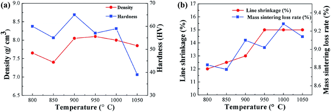 | ||
| Fig. 8 The effect of the sintering temperature on the physical properties of the sample: (a) the curve of the density and hardness; (b) the curve of the mass sintering loss rate and line shrinkage. | ||
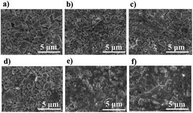
In order to further explore the effect of temperature on the properties of the sintered components, the microstructures of the samples at different sintering temperatures were characterized by SEM, and are shown in Fig. 9. It is shown that the copper particles were sintered together in an interconnected state at 800 °C and many irregular small grains can be seen, but many pores remained in the sample (Fig. 9a and b). As the atomic diffusion increased with an increase in the temperature, the separated microstructures were gradually sintered together and the pores were excluded (Fig. 9c and d), while the original small pieces of grain formed a large crystal (Fig. 9e). When the temperature reached 1050 °C, the pores were all excluded, and the parts of the microstructure were completely connected together, achieving superior metallurgical bonding (Fig. 9f). The relationship between the hardness, the line shrinkage and the temperature change (Fig. 8a) was also verified by the evolution of the microstructure observed by SEM. Because the probability of the copper atoms obtaining enough energy to cross the barrier to diffuse increases with the temperature increasing, the growth of a sintered neck between the microstructures is promoted. When the temperature reached 1050 °C, the original small separated grains grew into a large crystal, which is an important reason for the decline in hardness. Although, the sintering temperature of 1050 °C was favorable for the complete growth of the crystal from the SEM image, it is not an appropriate choice. This is because the physical properties of shrinkage, density and other parameters should also be considered. Besides, another heating treatment parameter (holding time) could be selected to further optimize the sintering process.
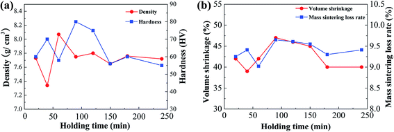 | ||
| Fig. 10 The effect of different holding times on the physical properties of a sample: (a) the curve of the density and hardness; (b) the curve of the mass sintering loss rate and volume shrinkage. | ||
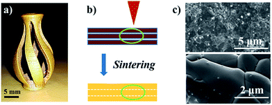 | ||
| Fig. 12 Analysis of the metal part and its metallurgical bonding: (a) manufactured metal part; (b) junction between the layers; (c) microstructure of the junction. | ||
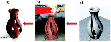
Based on metal paste injection 3D printing, complex 3D metal parts with good performance can be manufactured by optimizing the forming and sintering processes. However, there are more factors that affect the performance. For example, the dewaxing process of this subject is another important fundamental issue. To achieve the manufacture of precision parts, we need to improve the performance of the 3D printer equipment, combined with the optimization of the manufacturing process. Obviously, this study provides a new approach to the rapid manufacturing of complex 3D metals and alloys, which will have great potential in aviation, medicine, jewelry and other fields.
4 Conclusions
Copper powder and paraffin wax were utilized to prepare copper paste. Using laboratory-made 3D printing equipment without a mold and based on the MIM, 3D shapes of copper paste with fine surface flatness could be formed under the optimal printing conditions of a drive gear diameter of 7.5 mm, a retraction distance of 1.7 mm and a layer height of 0.55 mm. The TG-DTA curve indicates that the sintering process of copper paste can be initiated at approximately 300 °C, and the optimal conditions were a sintering temperature of above 950 °C with a holding time of 120 min. Based on our research, a metal component was manufactured with a complex 3D structure, dense microstructure, superior metallurgical bonding and flat surface. So it can be concluded that metal paste injection 3D printing reveals the feasibility of manufacturing complex 3D metals and alloys by means of a low-cost 3D printing technology without any mold.Conflicts of interest
There are no conflicts to declare.Acknowledgements
We gratefully acknowledge the financial support by the National Natural Science Foundation of China (Grant No. 51675496 and 51671091), and Wuhan City Applied Basic Research Project, China (No. 2017010201010126). This paper is CJHI contribution CJHIWZ-2017007. The authors acknowledge the financial support of a grant (CJHIXM-S201617) from the Center for Jewelry Heritage and Innovation, Hubei Provincial Key Research Base for Humanity and Social Sciences.References
- M. Vaezi, H. Seitz and S. Yang, A review on 3D micro-additive manufacturing technologies, Int. J. Adv. Manuf. Technol., 2013, 5, 1721–1754 CrossRef.
- L. I. Li, Q. I. Le-hua, X. U. Lin-feng and Y. Fang, Development of micro-fabrication technology based on material removal, Machinery Design & Manufacture, 2005, 4, 88–90 Search PubMed.
- W. Michaeli and R. Bielzer, Metal injection molding: Shaping sintered metal parts, Adv. Mater., 1991, 5, 260–262 CrossRef.
- T. Ebel, V. Friederici, P. Imgrund and T. Hartwig, 19–Metal injection molding of titanium, Titanium Powder Metall., 2015, 337–360 Search PubMed.
- R. M. German, Progress in titanium metal powder injection molding, Materials, 2013, 6, 3641–3662 CrossRef PubMed.
- E. Ergul, H. O. Gulsoy and V. Gunay, Effect of sintering parameters on mechanical properties of injection moulded Ti-6al-4v alloys, Powder Metall., 2009, 52, 65–71 CrossRef CAS.
- J. H. Martin, B. D. Yahata, J. M. Hundley, J. A. Mayer, T. A. Schaedler and T. M. Pollock, 3D printing of high-strength aluminium alloys, Nature, 2017, 549, 365–369 CrossRef CAS PubMed.
- U. Kalsoom, P. N. Nesterenko and B. Paull, Recent developments in 3D printable composite materials, RSC Adv., 2016, 6, 60355–60371 RSC.
- L. Hirt, A. Reiser, R. Spolenak and T. Zambelli, Additive Manufacturing of Metal Structures at the Micrometer Scale, Adv. Mater., 2017, 17, 1–30 Search PubMed.
- Y. Mao, Y. Yan, K. Wu, H. Xie and Z. Xiu, Non-equilibrium synthesis and characterization of n-type Bi2Te2.7Se0.3 thermoelectric material prepared by rapid laser melting and solidification, RSC Adv., 2017, 7, 21439–21445 RSC.
- O. A. Mohamed, S. H. Masood and J. L. Bhowmik, Experimental investigation of time-dependent mechanical properties of PC-ABS prototypes processed by FDM additive manufacturing process, Mater. Lett., 2017, 193, 58–62 CrossRef CAS.
- W. Jo, D. H. Kim, J. S. Lee, H. J. Lee and M. W. Moon, 3D printed tactile pattern formation on paper with thermal reflow method, RSC Adv., 2014, 4, 31764–31770 RSC.
- R. M. German, Progress in Titanium Metal Powder Injection Molding, Materials, 2013, 6, 3641–3662 CrossRef PubMed.
- A. Dehghan-Manshadi, M. J. Bermingham, M. S. Dargusch, D. H. StJohn and M. Qian, Metal injection moulding of titanium and titanium alloys: Challenges and recent development, Powder Technol., 2017, 319, 289–301 CrossRef CAS.
- S. Hwang, E. I. Reyes, K. S. Moon, R. C. Rumpf and N. S. Kim, Thermo-mechanical Characterization of Metal/Polymer Composite Filaments and Printing Parameter Study for Fused Deposition Modeling in the 3D Printing Process, J. Electron. Mater., 2015, 44, 771–777 CrossRef CAS.
- S. Hong, C. Sanchez, H. Du and N. Kiml, Fabrication of 3D Printed Metal Structures by Use of High-Viscosity Cu Paste and a Screw Extruder, J. Electron. Mater., 2015, 44, 836–841 CrossRef CAS.
- H. Ye, X. Y. Liu and H. Hong, Sintering of 17-4PH stainless steel feedstock for metal injection molding, Mater. Lett., 2008, 19, 3334–3336 CrossRef.
- R. Supati, N. H. Loh, K. A. Khor and S. B. Tor, Mixing and characterization of feedstock for powder injection molding, Mater. Lett., 2000, 2–3, 109–114 CrossRef.
- T.-H. Kim, S.-R. Lee, S. J. Yun, S. H. Lim and T.-S. Jang, Anisotropic diffusion mechanism in grain boundary diffusion processed Nd–Fe–B sintered magnet, Acta Mater., 2016, 112, 59–66 CrossRef CAS.
- R. Mohammadzadeh and M. Mohammadzadeh, Grain boundary and lattice diffusion in nanocrystal α-iron: An atomistic simulation study, Phys. A, 2017, 482, 56–64 CrossRef CAS.
| This journal is © The Royal Society of Chemistry 2017 |


