
 Open Access Article
 This Open Access Article is licensed under a Creative Commons Attribution-Non Commercial 3.0 Unported Licence
Corrosion mechanism for local enrichment of acids and copper ions in copper-insulating paper contacts leading to the acceleration of copper sulfide formation induced by dibenzyl disulfide
Sihang Gao a,
Lijun Yang*a,
Bangfei Dengb and
Jiang Zhanga
a,
Lijun Yang*a,
Bangfei Dengb and
Jiang Zhanga
aState Key Laboratory of Power Transmission Equipment and System Security and New Technology, Chongqing University, Chongqing, 400044, China
bState Grid Chongqing Electric Power Research Institute, Chongqing, 400015, China
First published on 15th November 2017
Abstract
Numerous failures of high-voltage transformers occur because of sulfur corrosion in oil-impregnated paper insulation containing dibenzyl disulfide (DBDS). This study determines the effects of DBDS, the copper-insulating paper contact, the insulating paper and the atmosphere on copper sulfide formation. Accelerated thermal aging experiments were conducted for mineral oil that contained DBDS and insulation windings under atmospheric (nitrogen/air) conditions. The corrosive sulfur deposits were quantified using SEM/EDX, ICP-AES and precipitation methods. Oil acidity was measured and analyzed. The study proposes a corrosion mechanism for local enrichment of acids and copper ions in copper-insulating paper contacts leading to the acceleration of sulfur corrosion.
1. Introduction
Oil-immersed power transformers are important in power systems. The main insulation system of transformers consists of insulating oil, oil-impregnated insulating pressboard, and insulation windings. Copper is a preferred conductive material due to its stable physicochemical properties and low electrical resistivity. Thus, it is extensively used in oil-immersed power transformers. Insulation windings comprise copper strips wrapped with insulating paper and immersed in transformer oil to provide insulation for current and voltage transmissions.1 However, copper corrosion still exists in electrical power equipment; thus, copper is vulnerable to corrosion-related failures.3 Numerous studies have illustrated that dibenzyl disulfide (DBDS) is one of the main corrosive sulfur compounds in transformer oil; it causes copper sulfide formation on insulation windings. Copper sulfide is a gray-black solid with high conductivity, which weakens the dielectric strength of oil-immersed paper and reduces insulation resistance.4–6 This failure in transformers has attracted considerable attention. Thus, copper sulfur corrosion in oil–paper insulation has been investigated in several studies.Recent studies have been performed to explore the corrosion mechanism of copper sulfide formation, influencing factors, and remedial procedures of corrosion in oil-immersed insulation. The Mitsubishi Company in Japan proposed a possible corrosion mechanism for copper sulfide formation.7 This corporation suggested that the reaction of copper and DBDS can form DBDS–Cu compound that diffuses through insulating oil. DBDS–Cu compound partially dissolves in oil and adsorbs onto insulation windings. DBDS–Cu compounds then decompose into copper sulfide, dibenzyl sulfide (DBS), and bibenzyl (BiBZ) on insulation windings. Another corrosion mechanism for copper sulfide formation was proposed by Facciotti et al.8 They studied the influence of DBDS, oxygen, time, and Cu–paper contact upon copper sulfide formation, proposed a contact-based mechanism to explain copper sulfide contamination of insulating paper, and investigated the detachment and mobilization of copper sulfide deposits from the copper surface into insulating paper. Oxygen was observed to interfere with surface interaction between copper sulfide and copper, which causes metal displacement. ABB Company in the United States stated that mercaptan (R-SH) is a major corrosive sulfur compound and that it can react with copper under aerobic condition to generate copper sulfide.9 Previous investigations have also revealed that copper sulfide formation is influenced by various factors, such as temperature, concentration of corrosive sulfur compound (i.e., DBDS), oxygen, and 2, 6-di-tert-butyl-p-cresol (DBPC).10–15 Some studies have shown that the addition of metal passivators can suppress corrosion of insulation windings to a certain extent and that the replacement of insulating oil fails to solve winding corrosion.16–18 The findings from these previous studies are illustrated and presented on CIGRE WG A2-40, which is used worldwide.19
In the presence of insulation windings, copper sulfide formation by insulating oils is considered a potential threat to oil-immersed transformers. Thus, several test methods have been adopted to detect corrosive and potentially corrosive sulfur compounds in used and unused insulating oils. The main test methods are as follows: DIN 51353,20 ASTM D 1275A, ASTM D 1275B,21 and IEC 62535.22 However, these test methods differ to a certain extent. For DIN 51353, a silver conductor is immersed in oil and heated for 18 h at 100 °C in a sealed glass headspace vial. For ASTM D 1275A and ASTM D 1275B, a copper conductor is immersed in oil and heated for 19 h at 140 °C and for 48 h at 150 °C, respectively, in a sealed glass headspace vial filled with nitrogen. However, these detection methods cannot identify oils containing potentially corrosive sulfur.22 Thus, International Electrotechnical Commission (IEC) prepared international standards for detecting potentially corrosive sulfur compounds in mineral insulating oils. Wrapped conductors immersed in oil under air condition are suitable for used and unused mineral oils. For IEC 62535, a piece of copper conductor wrapped with Kraft paper is immersed in oil and heated for 72 h at 150 °C in a sealed glass headspace vial filled with air. IEC 62535 is currently recognized as the most effective test method for detecting oils with potentially corrosive sulfur compounds. Copper conductors wrapped with Kraft paper and reaction conditions (under air condition) represent the main differences between IEC 62535 detection and other test methods.
Moreover, a large number of field samples have revealed that copper sulfide mainly deposits on the surface of copper strips and inner insulating paper. Based on the contact-based mechanism between copper strip and insulating paper,8 insulating papers may play an important role in copper sulfide deposition on insulation windings. Degradation of oil–paper insulation generates aging polar products, such as acidic substances and copper ions.23,24 Therefore, the role of insulating papers in copper sulfide deposition on insulation windings warrants further investigation.
The present study further explores the effect of DBDS, copper-insulating paper contact, insulating paper, and atmosphere on copper sulfide formation. A series of thermal aging experiments were conducted under different conditions. Macro and micro studies on insulation windings after aging experiments were described using scanning electron microscopy (SEM)/energy-dispersive X-ray spectroscopy (EDX). Inductively coupled plasma atomic emission spectrometry (ICP-AES) and precipitation method were used to quantify the corrosion degree of insulation windings; the acidity of insulating oil was also measured and analyzed. Combined with previous studies about corrosion mechanisms, the present study investigated the copper sulfide contamination of insulation windings.
2. Experimental
2.1 Sample preparation
Analytical-grade reagents (AR) were used. DBDS (AR, 99%) was purchased from China Huaxia Chemical Reagent Co., Ltd. The insulating oil used was Karamay #25 mineral oil provided by China Chongqing ChuanRun Petroleum Chemical Co., Ltd. Karamay mineral oil features favorable electrical properties and oxidation stability, and antioxidant (2,6-di-tert-butyl-4-methylphenol) mass concentration of 0.3% and maximum total sulfur content of 0.05%. This oil presents no detectable DBDS and metal passivator additives; it is also non-corrosive according to standard corrosion test IEC 62535.22 Table 1 lists the oil parameters according to specifications of ASTM D3487-2000 (II). Insulation windings were provided by China Chongqing ABB Transformer Co., Ltd. Copper strips were generated from an electrolytic tough pitch copper measuring 12 mm in width, 2 mm in thickness, and 70 mm in length. Each conductor was wrapped with four layers of 0.08 mm-thick insulating paper, which measured 20 mm × 100 mm × 0.08 mm. In the current experiment, insulation windings were divided into three categories (Table 2). The entire copper strip wrapped with insulating paper, the half of the copper strip wrapped with insulating paper, and the bare copper strip are defined as Windings I, II, and III, respectively.| Property | Mineral oil |
| Density, kg m−3 | 884.6 |
| Kinematic viscosity (40 °C), mm2 s−1 | 9.652 |
| Pour point, °C | <−24 |
| Flash point, °C | 143 |
| Acidity, mg KOH g−1 | <0.01 |
| Breakdown voltage (2.5 mm gap electrode, kV) | 38 |
| Antioxidant content (DBPC), % | 0.3 |
| Corrosive sulfur | Non-corrosive |
| Winding category | Description |
|---|---|
| Winding I | Copper strip is wrapped with insulating paper |
| Winding II | Half of the copper strip is wrapped with insulating paper, and the other half is bare |
| Winding III | Bare copper only |
2.2 Experimental setup and procedure
A series of thermal aging experiments were conducted under different conditions to explore the comprehensive effects of DBDS, copper-insulating paper contact, and atmosphere on copper sulfide formation. Mineral oil with 500 mg kg−1 DBDS and three types of insulation windings were aged at 130 °C under nitrogen or air condition. Table 3 shows the experimental conditions.| Winding category | Insulating oil | Thermal aging condition |
|---|---|---|
| Winding I | 100 mL oil with 500 mg kg−1 DBDS | At 130 °C under nitrogen or air environment |
| Winding II | ||
| Winding III |
Oil–paper insulation was gradually oxidized to generate a series of oxidation products. During this operation, acidic substances (e.g., oleic acid, formic acid, naphthenic acid, hydroxyl acid, and other acids) became deleterious. Various acids and acidic substances increase oil conductivity and accelerate the aging of solid fibers.27 Thus, the acidity of insulating oil directly reflects the aging degree of oils.2 The presence of more acidic substances in oil insulation usually results in higher oil acidity. Acidic substances include high and low molecular-weight acids and they are generated by the aging of oil–paper insulation in oil-immersed transformers. A clear synergy of the aging rates of solid fibers between moisture and low molecular-weight acids was found. No effect for high molecular-weight acids was observed. The partitioning of acids in oil–cellulose insulation is governed by molecular weight, that is, the lower the molecular weight the more the paper adsorbs, and higher the molecular weight the less the paper adsorbs; thus, most high molecular-weight acids mainly exist in insulating oil.28–30 Therefore, high molecular-weight acids easily dissolve in insulating oils. Low molecular-weight acids are more likely to transfer to insulating papers. Thus, specific amounts of oleic acid (AR, 95%), which simulated high molecular-weight acids, and formic acid (AR, 95%), which simulated low molecular-weight acids, were selected to simulate acids generated during the aging of oil–paper insulation. The AR of formic and oleic acids was graded 95.0%. Each type of winding involved seven experimental sets, including no acid, oleic acid (0.05, 0.1 mg KOH g−1), formic acid (0.05, 0.1 mg KOH g−1), and a combination of oleic and formic acids (0.025/0.025, 0.05/0.05 mg KOH g−1). Mineral oil with 500 mg kg−1 DBDS and three types of windings were aged at 130 °C with and without formic or oleic acids under nitrogen condition. The experimental conditions are shown in Table 4.
| Winding category | Insulating oil | Acid category | Serial number with different samples (acid, mg KOH g−1) | Thermal aging condition |
|---|---|---|---|---|
| Winding I, Winding II, Winding III | 100 mL oil with 500 mg kg−1 DBDS | Oleic acid, formic acid, oleic/formic acid | A: no acid, B: oleic acid (0.05), C: oleic acid (0.1), D: formic acid (0.05), E: formic acid (0.1), F: oleic/formic acid (0.025/0.025), G: oleic/formic acid (0.05/0.05) | At 130 °C for 360 h under nitrogen |
Aging experiment was conducted as follows.
Step 1. Insulating oil with 500 mg kg−1 DBDS and windings were placed in a vacuum chamber at 90 °C/50 Pa for 48 h. Afterward, windings were placed in oil at 40 °C/50 Pa and immersed for 48 h.
Step 2. The three types of winding and 100 mL oil with and without acids were placed in glass vessels, which were then placed in stainless tanks, filled with nitrogen (air), and sealed (opened).
Step 3. Stainless tanks were placed in an aging chamber at 130 °C, and insulation windings and insulating oils were retrieved from the stainless tank at intervals during aging.
For Winding II, half-bare copper strip was specified as area I, and the other half of the copper strip wrapped with insulating paper was designated as area II, as shown in Fig. 1.
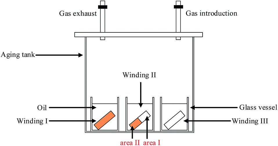 | ||
| Fig. 1 Configuration of experimental setup and winding samples used in the experiment. | ||
2.3 Characterization
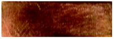
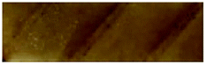
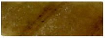
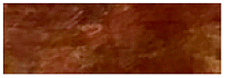
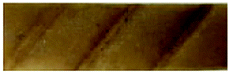
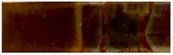
Four methods were applied to evaluate the corrosion degree of insulation windings qualitatively and quantitatively. The first method used the tarnish level chart ASTM D 130 to compare the contamination degrees of the copper strips.31 (Fig. 2).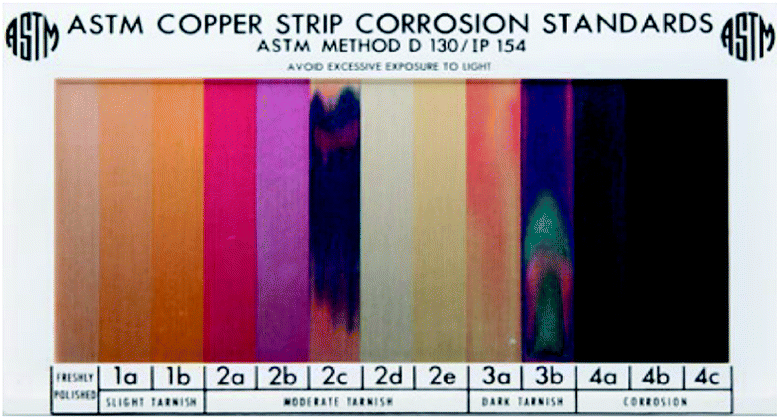 | ||
| Fig. 2 Color chart used in ASTM D 130 corrosive test. | ||
The second method employed SEM and EDX produced by TESCAN Company to analyze microscopic morphology and composition elements on the surface of insulation windings. The third method used ICP-AES to measure the amount of copper deposited on the insulating paper and the copper ions dissolved in oil. The test details and process of ICP-AES are presented below.
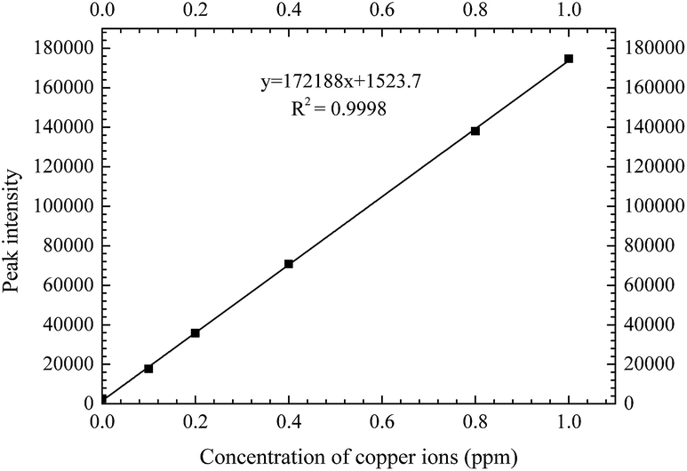
Step 1. The calibration curve for copper content should be determined. The copper content for a standard solution was 500 ppm. Different copper concentration solutions were configured through dilution (0, 0.1, 0.2, 0.4, 0.6, 0.8, and 1 ppm) and then analyzed by ICP-AES. The calibration curve could finally be determined. R2 reached at least 99.9%, as shown in Fig. 3.
 | ||
| Fig. 3 Calibration curve of copper ion concentration. | ||
Step 2. After the aging experiment, insulating paper/oil was placed into a crucible equipped with a lid, carbonized by an electric furnace, and then burned to ashes in a muffle furnace. The ashes were cooled to room temperature and dissolved in 4% nitric acid for 1 h.
Step 3. The solution was tested by using ICP-AES, and copper content was determined by comparing its peak intensity to the peak intensity of the standard solution. Each sample was tested four times via ICP-AES, and an error bar was added to the results.
The last method involved precipitation method, which was used to measure the amount of sulfur on the copper strips. The test is described as follows. Barium chloride solutions and nitric acid were reacted with copper sulfide. Precipitate was measured using a precipitation method, and the amount of sulfur deposited on the copper strip was then calculated.15 First, a copper strip was placed in a 1![[thin space (1/6-em)]](https://www.rsc.org/images/entities/char_2009.gif) :1 (v/v) nitric acid solution. Second, additional amount of barium chloride solution was added to nitric acid solution until precipitation ceased. Third, precipitate was filtered, transferred to crucibles, and then placed in a furnace for drying. Fourth, the crucible containing barium sulfate was removed from the furnace, cooled to room temperature, and weighed using an electronic balance.
:1 (v/v) nitric acid solution. Second, additional amount of barium chloride solution was added to nitric acid solution until precipitation ceased. Third, precipitate was filtered, transferred to crucibles, and then placed in a furnace for drying. Fourth, the crucible containing barium sulfate was removed from the furnace, cooled to room temperature, and weighed using an electronic balance.
Chemical reaction principles are described as follows:
| 16HNO3 + 3Cu2S → 3Cu(NO3)2 + 3CuSO4 + 10NO + 8H2O | (1) |
| CuSO4 + BaCl2 → BaSO4 + CuCl2 | (2) |
Contents are calculated as follows:
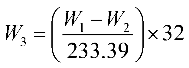 | (3) |
In general, copper sulfide generated in the corrosion can be deposited on the copper strip and insulating paper, the amount of copper sulfide deposited on the copper strip is represented by the content of sulfur and the amount of copper sulfide deposited on the insulating paper is embodied by the content of copper.
The acidity of insulating oils was measured by potentiometric titration according to IEC62021.27
3. Results
3.1 Surface morphologies of insulation windings
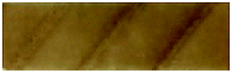
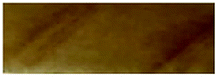
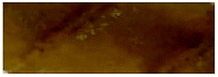
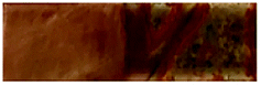
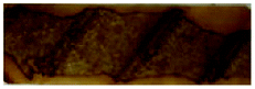
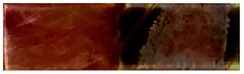
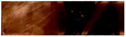
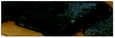
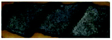
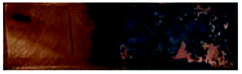
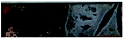
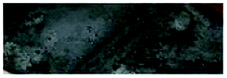
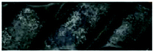
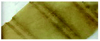
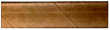
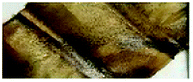
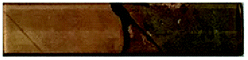
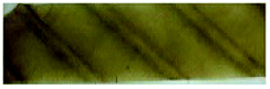
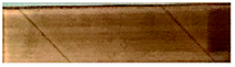
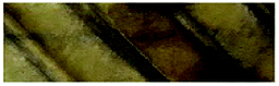
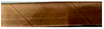
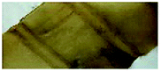
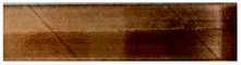
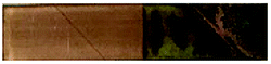
Table 5 shows the surface morphologies of insulation windings aged at 130 °C under nitrogen atmosphere. For Winding I, corrosion was indicated by visible gray-black deposits on copper strips and inner insulating paper. The corrosion degree of copper strips and inner insulating paper intensify with the increase in aging time, increasing from 2b to 3b according to the tarnish level chart ASTM D 130. However, few deposits accumulated on the outer insulation paper. For Winding II, some deposits were observed on area II of the copper strips and inner insulating paper, and corrosion degree of increased from 2b to 3b. However, no deposit was found on area I of the copper strips during aging. For Winding III, no deposit was observed on the copper strips during aging. These findings indicated that insulating paper may play a vital role in the formation of corrosive deposits. The bare copper strip cannot be corroded under nitrogen condition even when under high DBDS concentration in insulating oil.| Time | Sample | ||||
|---|---|---|---|---|---|
| Winding I | Winding II | Winding III | |||
| Copper | Inner paper | Copper | Inner paper | Copper | |
| 7 days | 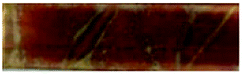 |
 |
 |
 |
 |
| 2b | 1a/2b (area I/II) | 1a | |||
| 14 days | 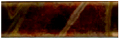 |
 |
 |
 |
 |
| 2c | 1a/2b (area I/II) | 1a | |||
| 21 days | 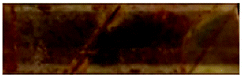 |
 |
 |
 |
 |
| 3a | 1a/3a (area I/II) | 1a | |||
| 28 days | 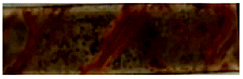 |
 |
 |
 |
 |
| 3a | 1a/3b (area I/II) | 1a | |||
| 35 days | 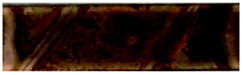 |
 |
 |
 |
 |
| 3c | 1a/3b (area I/II) | 1a | |||
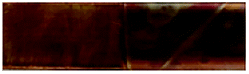
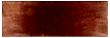
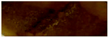
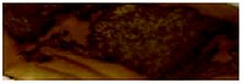
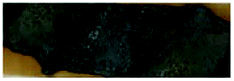
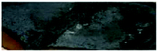
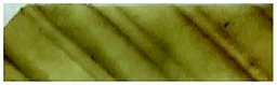
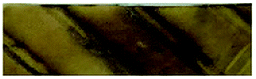
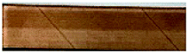
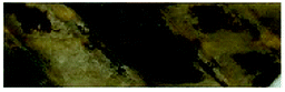
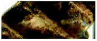
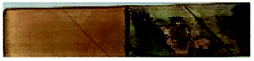
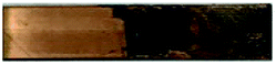
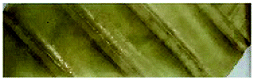
Table 6 provides the surface morphologies of insulation windings aged at 130 °C under air condition. For Winding I, numerous corrosive deposits accumulated on the copper strips and inner insulating paper, and corrosion was more serious than that under nitrogen condition. The corrosion degree of the copper strip increased from 3b to 4b with aging time, and almost no deposit accumulated on the outer insulating paper. For Winding II, a number of corrosive deposits were observed on area II of the copper strips and inner insulating paper, which indicated more serious corrosion than that under nitrogen condition. The corrosion degree of area II of the copper strip also increased from 3b to 4b with aging time. However, no deposit was observed on area I of the copper strips until the late phase of aging, and the corrosion degree at day 28 of aging reached 4b. For Winding III, a significant number of corrosive deposits were precipitated on the copper strips under air condition, indicating apparent corrosion of copper strips under such condition. With the increase in aging time, the corrosion degree of the copper strip increased from 3b to 4c. The corrosive deposits on the insulation windings under air condition were darker than those under nitrogen condition. Moreover, the amount of corrosive deposits on insulation windings under air condition was considerably higher than that under nitrogen condition. Therefore, based on the preliminarily results, the existence of oxygen-accelerated corrosion resulted in a large amount of corrosive deposits on insulation windings.
| Time | Sample | ||||
|---|---|---|---|---|---|
| Winding I | Winding II | Winding III | |||
| Copper | Inner paper | Copper | Inner paper | Copper | |
| 7 days | 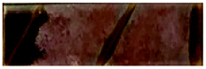 |
 |
 |
 |
 |
| 3b | 1a/3b (area I/II) | 3b | |||
| 14 days | 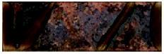 |
 |
 |
 |
 |
| 4a | 1a/4a (area I/II) | 4a | |||
| 21 days | 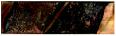 |
 |
 |
 |
 |
| 4a | 2c/4a (area I/II) | 4b | |||
| 28 days |  |
 |
 |
 |
 |
| 4b | 4b/4b (area I/II) | 4b | |||
| 35 days | 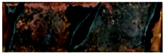 |
 |
 |
 |
 |
| 4b | 4b/4b (area I/II) | 4c | |||
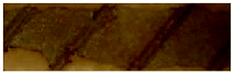
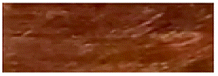
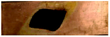
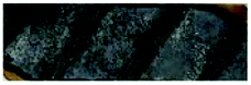
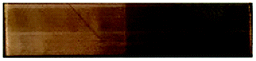
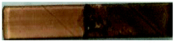
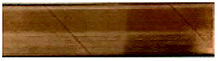
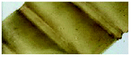
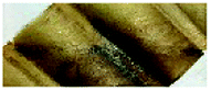
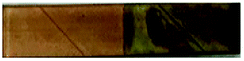
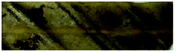
Table 7 shows the surface morphologies of the insulation windings after the acid experiment at 130 °C under nitrogen condition. For Winding I, more corrosive deposits were observed on the windings in acid-containing oil than in the original oil without acids. As the amount of acids increased in the insulating oil, the corrosion degree of the windings was intensified. Moreover, the corrosion degree of the copper strip in Winding I increased with the acid-containing oil, with formic acids showing the highest corrosion degree on the copper strip, followed by the combination of oleic and formic acids and oleic acids alone. The corrosion degree of the inner insulating paper in Winding I also increased with the acid-containing oil; however, the highest corrosion degree of paper was observed with oleic acids, followed by the combination of oleic and formic acids and formic acids alone. For Winding II, corrosive deposits were also deposited on area II of the copper strips and inner insulating papers, and the surface morphologies of area II were similar to the results for Winding I. However, regardless of the acid content, no deposit was found on area I of the copper strips. For Winding III, no deposit was observed on the copper strips. The bare copper strip could not be corroded with acid-containing corrosive oil. Consequently, acids accelerated the formation of corrosive deposits on paper-wrapped copper strips.
| Acid (mg KOH g−1) | Sample | ||||
|---|---|---|---|---|---|
| Winding I | Winding II | Winding III | |||
| Copper | Inner paper | Copper | Inner paper | Copper | |
| No acid | 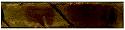 |
 |
 |
 |
 |
| Oleic acid (0.05) | 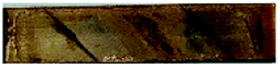 |
 |
 |
 |
 |
| Oleic acid (0.1) | 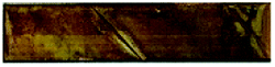 |
 |
 |
 |
 |
| Formic acid (0.05) | 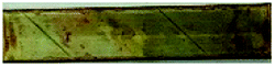 |
 |
 |
 |
 |
| Formic acid (0.1) |  |
 |
 |
 |
 |
| Oleic/formic acid (0.025/0.025) | 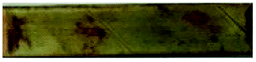 |
 |
 |
 |
 |
| Oleic/formic acid (0.05/0.05) | 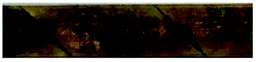 |
 |
 |
 |
 |
3.2 Microscopic morphology and composition element analysis of insulation windings
SEM equipped with EDX was used to observe microscopic morphology and analyze the composition elements on the surface of insulation windings. Fig. 4 displays the SEM images and EDX maps of the copper strips under three different aging conditions. For Winding I, some corrosive particles on the copper strips were observed at day 21 of aging under nitrogen condition. Large areas of corrosive particles with different shapes and sizes were deposited on the copper strip of Winding I at day 21 of aging under air condition. More corrosive particles were observed for Winding I immersed in oil containing formic acids. According to the EDX maps of the copper strip, the atomic percentage of oxygen and sulfur on the copper strip under air condition was higher than that under nitrogen condition. This result indicated that copper sulfide and oxides increased and that oxygen accelerated the corrosion, which led to a large amount of corrosive deposits on the insulation windings.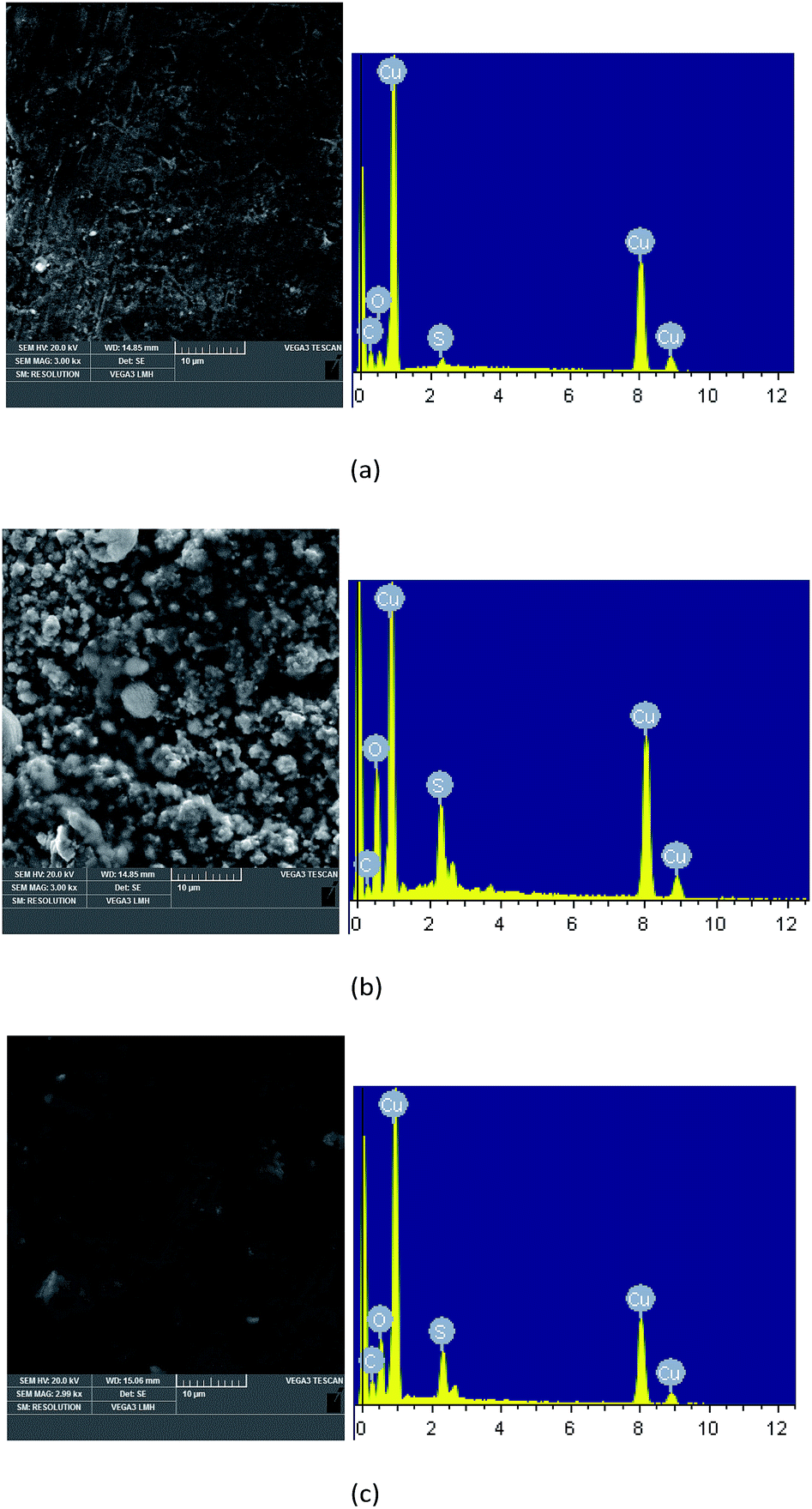 | ||
| Fig. 4 SEM images and EDX maps of the copper strips under different aging conditions. (a) Winding I at day 21 of aging under nitrogen condition. (b) Winding I at day 21 of aging under air condition. (c) Winding I in oil containing formic acids (0.05 mg KOH g−1). | ||
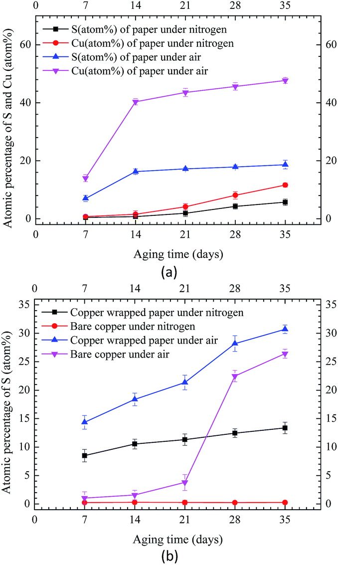
Carbon, oxygen, copper, and sulfur were detected by EDX on the surface of corroded insulation windings. Fig. 5 shows the atomic percentages of sulfur and copper on Winding I under nitrogen and air conditions, respectively. As shown in Fig. 5(a), sulfur and copper contents were measured on the inner insulating paper under air and nitrogen conditions, respectively. Under nitrogen and air conditions, the atomic percentage ratio of copper and sulfur on insulating paper reached 2 and more than 2, respectively. These results indicated that some amounts of copper sulfide were deposited on insulation windings after the reaction of DBDS and copper.8 Under air condition, insulation windings presented significantly higher sulfur and copper contents than those under nitrogen condition. This result indicated that copper sulfide deposition on insulation windings increased due to the presence of oxygen, which accelerated the corrosion degree of insulation windings.
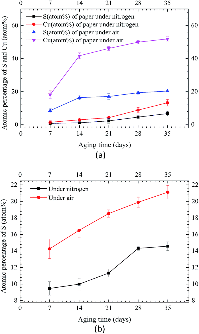 | ||
| Fig. 5 EDX quantitation of sulfur and copper on Winding I under nitrogen and air conditions. (a) EDX results of inner paper. (b) EDX results of copper strip. | ||
Fig. 6 shows the atomic percentages of sulfur and copper on area II of Winding II under nitrogen and air conditions, respectively. As depicted in Fig. 6(a), sulfur and copper contents on the inner insulating paper under air condition were considerably higher than that under nitrogen condition. This finding was similar to the results for Winding I. As shown in Fig. 6(b), sulfur content on area I of the copper strip was extremely low under nitrogen condition, indicating that no copper sulfide formed under such condition. However, under air condition, sulfur content on area I of the copper strip increased rapidly at the late phase of aging, indicating that oxygen accelerated corrosion.
 | ||
| Fig. 6 EDX quantitation of sulfur and copper on Winding II under nitrogen and air conditions. (a) EDX results of inner paper. (b) EDX results of copper strip. | ||
Fig. 7 shows the atomic percentages of sulfur on the copper strip for Winding III under nitrogen and air conditions. Results demonstrated extremely low sulfur content on the copper strip under nitrogen condition and high sulfur content on the copper strip under air condition. These findings indicated that under oxygen condition, the reaction of DBDS and copper can corrode bare copper strips. By contrast, bare copper strips were difficult to corrode under nitrogen condition.
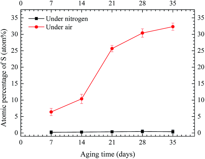 | ||
| Fig. 7 EDX quantitation of sulfur on copper strip for Winding III under nitrogen and air conditions. | ||
3.3 Physicochemical properties of insulating oil
Fig. 8 shows the copper ions and oil acidity in different samples. For the three types of insulation windings, the concentration of copper ions and oil acidity were considerably higher under air condition than those under nitrogen atmosphere. More copper ions promoted oxidation and accelerated the aging of oil, thereby subsequently increasing conductivity and oil acidity.26 As shown in Fig. 8(a) and (b), for thermal aging under nitrogen condition, Winding I showed the least number of copper ions but exhibited the highest acidity. Winding III contained the highest number of copper ions but presented the lowest acidity. Winding I presented less copper ions but higher acidity than Windings II and III. Results agreed with those of the thermal aging under air condition. These findings indicated that the presence of insulating paper increased oil acidity and that oil–paper insulation was gradually oxidized and generated a series of oxidation products, including deleterious acidic substances and copper ions, thereby increasing the aging of insulating oil. However, additional insulating paper decreased the dissolution of copper ions in oil, indicating that these materials prevented diffusion of copper ions in oil.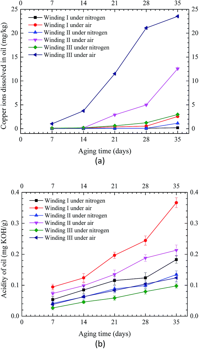 | ||
| Fig. 8 Copper ions and acidity of insulating oil in different samples under nitrogen and air conditions. (a) Copper ions of oil. (b) Oil acidity. | ||
Fig. 9 shows the normalized amount of copper and sulfur deposited on the insulating paper and copper strip, respectively (area of copper strip was 20.08 cm2, area of paper was 20 cm2, half of the copper area was 10.04 cm2, and half of the paper area was 10 cm2). Fig. 10 shows the copper ions of the insulating oil for the three types of windings in the acid experiment. As shown in Fig. 9 and 10, higher amounts of copper were deposited on the insulating paper in oil with acids than those in oil without acids. The same trend was observed in the amounts of sulfur deposited on the copper strips and the concentrations of copper dissolved in oils. Generally, the total amount of copper sulfide in oil with acids was considerably higher than that in oil without acids, and the amount of copper sulfide formation increased with the increase of dissolution of acids in oil. In comparison of Winding I and area II of Winding II, the amount of copper deposited on the insulating paper per unit area showed the same trend, along with the amount of sulfur deposited on the copper strip per unit area. Moreover, the amount of copper deposited on paper and the concentration of copper ions in oil with formic acids were lower than those in oil with oleic acids. By contrast, the amount of sulfur deposited on the copper strips in oil with formic acids was higher than that in oil with oleic acids. For Winding III and area I of Winding II, no sulfur was deposited on the copper strips in oil with acids. These findings suggested that the bare copper strip could not be corroded with acid-containing oil and that copper sulfide easily dissolved in oleic acid, which simulated high molecular-weight acids compared with formic acid, which represented low molecular-weight acids. Formic acid was more conducive to the copper sulfide formation on the copper strip than oleic acid.
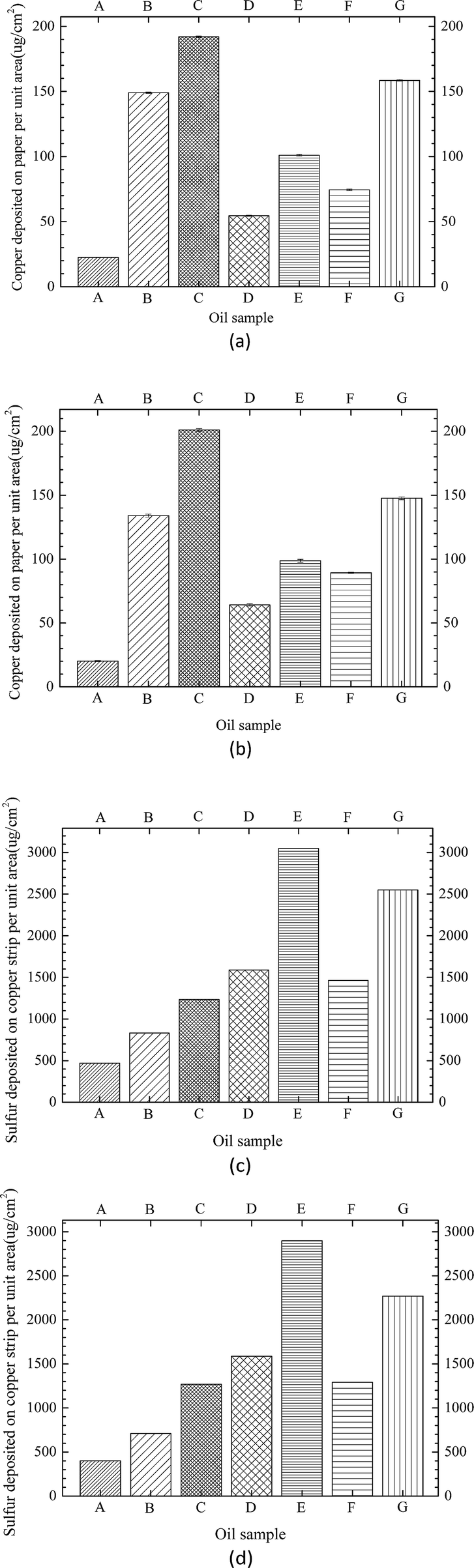 | ||
| Fig. 9 Normalized amounts of copper and sulfur deposited on insulating paper and copper strip for different oil sample compositions (see Table 4). (a) Copper content of paper for Winding I. (b) Copper content of paper for area II of Winding II. (c) Sulfur content of copper strip for Winding I. (d) Sulfur content of copper strip for area II of Winding II. | ||
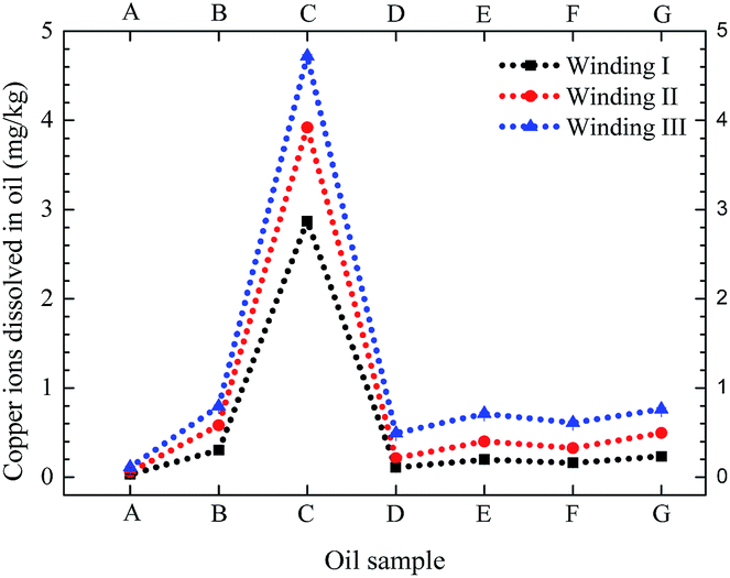 | ||
| Fig. 10 Copper ion concentration in insulating oil containing different acidic additives (see Table 4) from three types of winding (see Table 3). | ||
Meanwhile, according to the results of Fig. 9, it can be seen that the amount of sulfur deposited on copper strip was much higher than the amount of copper deposited on paper. Copper and innermost layer paper were all corroded, but the copper as conductor can be directly react with DBDS to form Cu2S, then some of Cu2S migrate to innermost layer paper, resulting in amount of Cu2S deposited on the copper was certain higher than that on the paper.7,12
4. Discussion and analysis
According to the preliminarily experimental results, the existence of paper-wrapped resulted in a large amount of corrosive deposits on insulation windings, however, bare copper strip cannot be corroded under nitrogen condition even when under high DBDS concentration in insulating oil. Acidic substances and copper ions are the main reason.Oil–paper insulation was gradually oxidized to generate the acidic substances, especially the degradation of insulating paper resulted in a large amount of low molecular-weight acids. It has been reported that DBDS partially decomposed into R-SH and other single-ring products under high-temperature conditions and with the presence of acidic substances,25 as shown in Fig. 11(a). The corrosion activity of R-SH is stronger than that of DBDS, leading to the acceleration of sulfur corrosion. The degradation of organic sulfur compounds involved an oxidative attack that was localized at sulfur atoms, whereas R-SH molecules were oxidized, not only copper sulfide formation, but also some DBDS regeneration, as shown in Fig. 11(b). Acidic substances accelerated copper sulfide formation (Fig. 12).
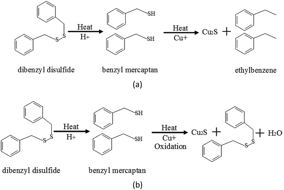 | ||
| Fig. 11 Reaction in the degradation of DBDS into benzyl mercaptan and its oxidation. (a) Degradation of DBDS into benzyl mercaptan. (b) Oxidation reaction of benzyl mercaptan. | ||
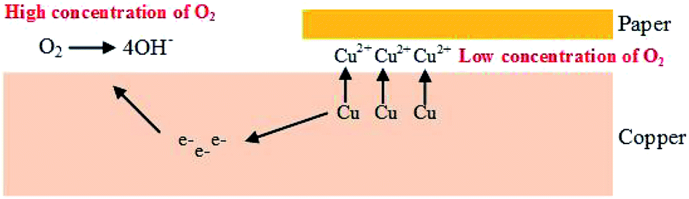 | ||
| Fig. 12 Oxygen concentrations cell induced by the existence of paper-wrapped copper. | ||
Copper sulfide formation on insulation windings was expected to occur through the reaction of DBDS and copper ions. Copper was polarized positively, whereas sulfur was polarized negatively. Radicals in acid-containing oil can accelerate the bonding of copper and DBDS to promote corrosion,14 leading to the acceleration of sulfur corrosion.
During the operation of oil-immersed transformer, both insulating paper and oil may inevitably connect with copper, so there are always some copper ions found in oil. It also should be noted that galvanic corrosion happened in oil–paper insulation.23 For paper-wrapped copper, paper wrapped copper lead to low oxygen concentrations between paper and copper, forming anode, and cathode was formed on the bare copper. Anodic processes (oxidation action) resulted in the acceleration of copper ions, as expressed in the following formulas:
Anode:
| Cu − ne−→ Cun+ | (1) |
Cathode:
| O2 + 2H2O + 4e− → 4OH− | (2) |
In general, the existence of paper-wrapped accelerated copper ions adsorption, which reacted with DBDS to generate copper sulfide, and the removal of paper eliminated the diffusion barrier of copper ions, the diffusion of copper ions may significantly affected sulfur corrosion.23 An increase in acidity also promoted the release of copper ions, leading to the acceleration of sulfur corrosion and oil–paper aged. And the oxidation oil are significantly influenced by copper release, which resulted in hydrogen peroxide decomposition and free radical formation, this process would promote the oxidation process of the insulation oil.23
| ROOH + Cu+ → RO˙ + Cu2+ + OH− | (3) |
| ROOH + Cu2+ → ROO˙ + Cu+ + H+ | (4) |
Moreover, copper release kinetics could also be influenced by oxidation of oil–paper in turn, and oxygen concentration contributed to a surge in copper ions, this phenomenon accelerated corrosion and resulted in corrosion of bare copper strips.23
Due to the strong adsorption of paper, some polar molecules, including copper ions and acidic substances, can be adsorbed,19 especially the innermost insulating paper that directly contact with copper, thereby increasing the concentration of H+ and Cu2+ region between the copper conductor and insulating paper. Thus, local enrichment of acids and copper ions in copper-insulating paper can promote sulfur corrosion, which served as an important precondition of sulfur corrosion (Fig. 13).
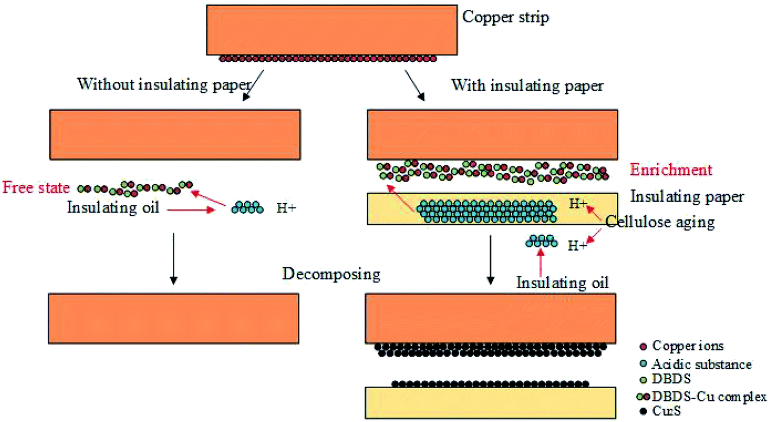 | ||
| Fig. 13 Schematic mechanism for the local enrichment of copper ions and acids between copper conductor and paper for the acceleration of copper sulfide formation. | ||
5. Conclusion
Based on collected experimental data and corrosion theory, the present study proposes a corrosion mechanism for local enrichment of copper ions and acids in copper-insulating paper contact leading to the acceleration of copper sulfide formation. The amount of formed copper sulfide can be increased by the presence of insulating paper, and acids promote copper sulfide formation on insulation windings. Increase in oxygen also contributes to a surge in copper ion dissolution in oil. This dissolution can accelerate corrosion and result in the corrosion of insulation windings. Thus, monitoring and controlling the oxygen content of transformer oil are remarkably instructive and helpful for operations. As caused by strong adsorption ability of insulating paper, degradation of oil–paper insulation results in increased amounts of acids and copper ions adsorbed by insulating paper. Increase in acids and copper ions increases the concentrations of H+ and copper ion areas between the copper conductor and insulating paper. These conditions can significantly promote corrosion. Moreover, the local enrichment of acids and copper ions in copper-insulating paper is an important precondition in copper sulfide corrosion.Conflicts of interest
There are no conflicts to declare.Acknowledgements
The authors would like to acknowledge the National Science Foundation of China (51277187) and Fund Project of State Grid Corporation of China, Jiangsu (J2017034).References
- R. J. Liao, L. J. Yang and J. Li, IEEE Trans. Dielectr. Electr. Insul., 2011, 18, 303–311 CrossRef.
- T. K. Saha and P. Purkait, IEEE Trans. Dielectr. Electr. Insul., 2008, 15, 568–582 CrossRef.
- F. Scatiggio, V. Tumiatti, R. Maina, M. Tumiatti, M. Pompili and R. Bartnikas, IEEE Trans. Power Delivery, 2008, 23, 508–509 CrossRef.
- CIGRE WG A2–32, Final Report No. 378, 2009 Search PubMed.
- R. Maina, V. Tumiatti, F. Scatiggio, M. Pompili and R. Bartnikas, IEEE Trans. Power Delivery, 2011, 26, 2391–2393 CrossRef.
- R. M. De Carlo, M. C. Bruzzoniti, C. Sarzanini, R. Maina and V. Tumiatti, IEEE Electrical Insulation Magazine, 2013, 20, 557–565 CAS.
- S. Toyama, J. Tanimura, N. Yamada, E. Nagao and T. Amimoto, IEEE Trans. Dielectr. Electr. Insul., 2009, 16, 509–515 CrossRef CAS.
- M. Facciotti, P. S. Amaro, A. F. Holt, R. C. Brown, P. L. Lewin, J. A. Pilgrim and P. N. Jarman, Corros. Sci., 2014, 84, 172–179 CrossRef CAS.
- J. Hajek, M. Dahlund, L. Patterson and G. Bennstam, ABB Review, 2004, 3, 61–63 Search PubMed.
- F. Kato, T. Amimoto, E. Nagao, N. Hosokawa and J. Tanimura, IEEE Trans. Dielectr. Electr. Insul., 2011, 18, 1869–1876 CrossRef CAS.
- T. Amimoto, N. Hosokawa, E. Nagao, J. Tanimura and S. Toyama, IEEE Trans. Dielectr. Electr. Insul., 2009, 16, 1489–1495 CrossRef CAS.
- S. Toyama, K. Mizuno, F. Kato, E. Nagao, T. Amimoto and N. Hosokawa, IEEE Trans. Dielectr. Electr. Insul., 2011, 18, 1877–1885 CrossRef CAS.
- S. Ren, L. Zhong, Q. Yu, X. Cao and S. Li, IEEE Trans. Dielectr. Electr. Insul., 2012, 19, 849–854 CrossRef CAS.
- H. Kawarai, Y. Fujita, J. Tanimura, S. Toyama, N. Yamada, E. Nagao and T. Amimoto, IEEE Trans. Dielectr. Electr. Insul., 2009, 16, 1430–1435 CrossRef CAS.
- V. Tumiatti, C. Roggero, M. Tumiatti, S. D. Carlo, R. Maina and S. Kapila, IEEE Trans. Dielectr. Electr. Insul., 2012, 19, 1633–1641 CrossRef CAS.
- J. Wada, G. Ueta and S. Okabe, IEEE Trans. Dielectr. Electr. Insul., 2013, 20, 307–316 Search PubMed.
- T. Amimoto, E. Nagao, J. Tanimura, S. Toyama and N. Yamada, IEEE Trans. Dielectr. Electr. Insul., 2009, 16, 257–264 CrossRef CAS.
- P. Wiklund, M. Levin and B. Pahlavanpour, IEEE Electrical Insulation Magazine, 2007, 23, 6–14 CrossRef.
- CIGRE WG A2–40, Final Report No. 625, 2015 Search PubMed.
- DIN 51353, 1985.
- ASTM D 1275, 2006.
- IEC 62535, 2008.
- O. Sevastyanova, B. Pasalskiy and B. Zhmud, Engineering, 2015, 7, 514–529 CrossRef.
- T. K. Saha, IEEE Trans. Dielectr. Electr. Insul., 2003, 10, 903–917 CrossRef CAS.
- L. Lewand and S. Reed, 75th Annual International Doble Client Conference, 2008, 1–20 Search PubMed.
- L. J. Liao, C. Tang and L. J. Yang, IET Electric Power Applications, 2009, 3, 407–412 CrossRef.
- IEC62021, 2003.
- L. E. Lundgaard, W. Hansen, D. Linhjell and T. P. Terence, IEEE Trans. Power Delivery, 2004, 1, 230–238 CrossRef.
- L. E. Lundgaard, W. Hansen, S. Ingebrigtsen, D. Linhjell and M. Dahlund, IEEE Int. Conf. Dielectr. Liq., 15th, 2005, 381–384 CAS.
- L. E. Lundgaard, W. Hansen and S. Ingebrigtsen, IEEE Trans. Dielectr. Electr. Insul., 2008, 2, 540–546 CrossRef.
- ASTM D 130, 2012.
| This journal is © The Royal Society of Chemistry 2017 |