
 Open Access Article
 This Open Access Article is licensed under a Creative Commons Attribution-Non Commercial 3.0 Unported Licence
Comparison of the characteristic properties of reduced graphene oxides synthesized from natural graphites with different graphitization degrees
Xuan Jiao ab,
Yangshuai Qiu*ab,
Lingyan Zhangab and
Xudong Zhangab
ab,
Yangshuai Qiu*ab,
Lingyan Zhangab and
Xudong Zhangab
aSchool of Resources and Environmental Engineering, Wuhan University of Technology, Luoshi Road 122, Wuhan, Hubei 430070, China. E-mail: liucanviva@whut.edu.cn
bHubei Province Key Laboratory for Processing of Mineral Resources and Environment, Wuhan University of Technology, Luoshi Road 122, Wuhan, Hubei 430070, China
First published on 13th November 2017
Abstract
In this study, an investigation on the characterization of reduced graphene oxides (rGOs) prepared from natural graphites with different graphitization degrees using Hummers method was conducted. X-ray diffraction, X-ray photoelectron spectroscopy, Fourier transform infrared spectroscopy, Raman spectroscopy, atomic force microscopy and electrochemical performance were performed to characterize the as-prepared graphene oxides (GOs) and rGOs. The results demonstrate that graphites with a lower graphitization degree are more easily oxidized due to the active carbon atoms exposed on their edges and the effective diffusion of oxidants that intercalate into the graphitic layers. In addition, graphites with a low graphitization degree were more suitable for the synthesis of thin layer graphene with a high defect degree and small size in the in-plane sp2 domains as well as a relatively high specific capacitance.
1. Introduction
Since the discovery of graphene in 2004, two-dimensional graphitic material containing hexagonal networks comprised of carbon atoms have gradually gained increasing amounts of attention and research efforts for industrial applications worldwide.1,2 Graphene is extensively applied in electronics, energy storage, photovoltaic devices, membrane materials, resources recovery, biological engineering, biocatalysis, original filtration, and lightweight/strong composite materials, attributing to its superior properties, such as outstanding electrical conductivity, high optical transparency, favorable adsorption performances, high thermal conductivity and mechanical strength.3–7 With the development of advanced technology, several useful methods have been proposed to synthesize graphene, including mechanical exfoliation,8 liquid-phase exfoliation,9 bottom-up assembly,10 epitaxial growth via thermal graphitization of silicon carbide,11 unzipping carbon nanotubes,12 epitaxial growth of graphene via chemical vapor deposition (CVD) on substrates13,14 and the reduction of graphene oxide.15,16 Among these methods, chemical reduction in wet conditions using graphene oxide has been considered as a cost-effective and optimized approach for the large-scale production of graphene materials.17Graphite oxide (GrO) is regarded as a superior precursor for the synthesis of graphene and the electrochemical reduction and chemical reduction methods have been demonstrated to be efficient and productive methods.18,19 During the oxidation and reduction processes with the exfoliation of GrO, graphene oxide (GO) and reduced graphene oxide (rGO) are generated. Both GO and rGO are graphene derivatives that have structures containing defects due to the oxygen-containing functional groups exposed on the edges of the carbon layers. It is evident that numerous variable factors could affect the structure of graphene and the properties of graphene products notably depend on the structure.20 As previously reported in the literature, the graphite used as starting material could directly influence the structure and properties, hence, the selectivity of the raw material plays an important role in the preparation of graphene.
Due to its abundant reserves worldwide, graphene is usually prepared from the natural graphite. It has been reported that the crystallinity of the graphite, used as the starting material, can strongly influence the graphene layers formed in the chemical reduction process.21 In general, natural graphite can be classified into crystalline graphite and aphanitic graphite. On the basis of the different crystalline morphologies, as well as the presence of oxygen-containing groups on the edges of the structural layers, there is a remarkable difference on the graphitization degree of natural graphites, which can be used to evaluate the development of the graphitic structure in various carbon materials.22–25 The degree of graphitization, as a rule, is the extent to which a material approaches the ideal graphite structure, which can be distinguished using XRD and theoretical calculations based on the values of d002. As reported in the literature, numerous factors were found to affect the characteristics of rGO, such as the lateral size,26 impurity content,20 geographical origin27 and various synthesis methods.28 However, the concept of graphitization degree of natural graphite has recently attracted attention in scientific research as well as its connection with the characteristic properties of graphitic derivatives. In addition, few studies have investigated the effects of the graphitization degree of graphite used as raw material on the characteristics and properties of rGO prepared from these materials.
Therefore, natural graphites with different graphitization degree was used to prepare GOs and rGOs using the chemical reduction method. In this study, the objective was to focus on the effect of the different graphitization degree in four types of natural graphites on the rGO synthesized from these materials whilst comparing their characteristics and properties.
2. Experimental
2.1. Materials and chemicals
Samples of natural graphites with different graphitization degree were classified into four types, marked as VG, LG, FG and AG, and used as the starting materials to prepare rGO. In addition, the natural graphite were obtained by screening with the size fraction at 38–45 mm, whose fixed carbon contents exceeded 99%. Potassium permanganate, sodium nitrate, 98% sulfuric acid, 36% hydrochloric acid, 30% hydrogen peroxide and 85% hydrazine hydrate were all purchased from Sinopharm Chemical Reagent Co., Ltd, China. All the regents were of analytical grade, used without further purification. Deionized water with a resistivity of 18.25 MΩ cm was used in this work and was produced using a Milli-Q Direct 16 purification system.2.2. Preparation of GO and rGO
GrO samples were prepared as reported previously using Hummers' method.29 First of all, 3.0 g of natural graphite and 1.5 g of NaNO3 were added to 69 mL of H2SO4 and stirred using a magnetic stirrer and cooled using an ice-water bath. Next, 9.0 g of KMnO4 was added slowly with continuous stirring keeping the temperature less than 10 °C. Then, the temperature was allowed to increase to 37 °C for 2 h. After that, 138 mL of deionized water was added dropwise to the mixture at 96 °C and stirred for 30 min. Then, 420 mL of deionized water was added to dilute the mixture as well as 30 mL of and aqueous solution of H2O2 to remove the residual KMnO4. Finally, the mixture was washed with 5% HCl aqueous solution and deionized water while centrifuging at 2500 rpm for 30 min. The GrO was washed without SO42− and dried at 60 °C for 24 h in vacuo.The as-prepared GrO obtained from the natural graphites with different graphitization degrees were labeled as GrO-VG, GrO-LG, GrO-FG and GrO-AG. After milling the GrOs into powder, the samples were dispersed in deionized water to form yellow-brown suspensions. Next, the suspensions were ultrasonically exfoliated using a Cole Parmer ultrasonic processor with 60% amplitude for 12 min. Then, the suspensions were centrifuged at 2800 rpm for 20 min to remove the non-exfoliated GrO. GOs in the supernatants obtained from GrO-VG, GrO-LG, GrO-FG and GrO-AG, and were labeled as GO-VG, GO-LG, GO-FG, and GO-AG, respectively.
rGO samples were obtained through the reduction of the as-prepared GO supernatants. At first, 5 mL of 85% hydrazine hydrate was added to the suspension, while the pH was adjusted to 10 using a 0.1 M NaOH aqueous solution. Subsequently, the reaction mixture was kept at 97 °C for 8 h, then filtered and washed with methanol and water for several times. The rGO powders were obtained after drying at 60 °C for 24 h in vacuo. The rGOs obtained after the reduction of GO-VG, GO-LG, GO-FG and GO-AG were labelled as rGO-VG, rGO-LG, rGO-FG and rGO-AG, respectively.
2.3. Measurements
X-ray diffraction (XRD) patterns were recorded in the range of 2θ = 5–80° using a D8 Advance model X-ray powder diffractometer (Bruker Corporation, Stuttgart, Germany) with Cu Kα radiation (λ = 1.5406 Å).X-ray photoelectron spectroscopy (XPS) patterns were obtained on a VG Multilab 2000 (Thermo Electron Corporation, Waltham, MA, USA) with a monochromatic Al X-ray source operating at 300 W. The spectra were corrected using the C 1s peak at 284.6 eV.
The Fourier transform infrared (FT-IR) spectra within the range from 400 to 4000 cm−1 were recorded on a Nicolet IS-10 infrared spectrometer (Nicolet Corporation, Madison, USA).
The Raman spectra of all the samples were obtained using a Renishaw INVIA Raman microscope (Renishaw Corporation, Gloucestershire, England) equipped with an Ar laser probe at the 514.5 nm mode, recorded in the Raman region from 500 to 3500 cm−1.
Atomic force microscopy (AFM) images of the as-prepared rGOs were recorded using a Bruker MultiMode 8 AFM (Bruker Corporation, Stuttgart, Germany) in peak force tapping mode.
Cyclic voltammograms (CV) were measured using a CHI 660E electrochemical workstation (Shanghai chenghua instrument Co. Ltd, Shanghai, China) in a three-electrode configuration at ambient temperature, in which the rGO-modified glassy carbon electrode, a saturated calomel electrode and a slice of platinum served as the working electrode, reference electrode and auxiliary electrode, respectively. In addition, a 6 mol L−1 KOH aqueous solution was used as the electrolyte. The CV tests were conducted in the sweep potential range from −0.9 to 0.1 V at a scan rate of 10 mV s−1. The specific capacitance of the electrodes could be calculated using the following equation:
 | (1) |
3. Results and discussion
3.1. Characterization of the various graphites
The XRD patterns of the four natural graphites with different graphitization degrees are shown in Fig. 1. All the patterns exhibited strong and sharp peaks at approximately 2θ = 26.45° and other peaks with relatively weak intensity appearing at around 2θ = 54.61°, corresponding to the (002) and (004) reflection planes of natural graphite, respectively. The degree of graphitization for the starting graphite samples can be calculated based on the following equation:30–32
 | (2) |
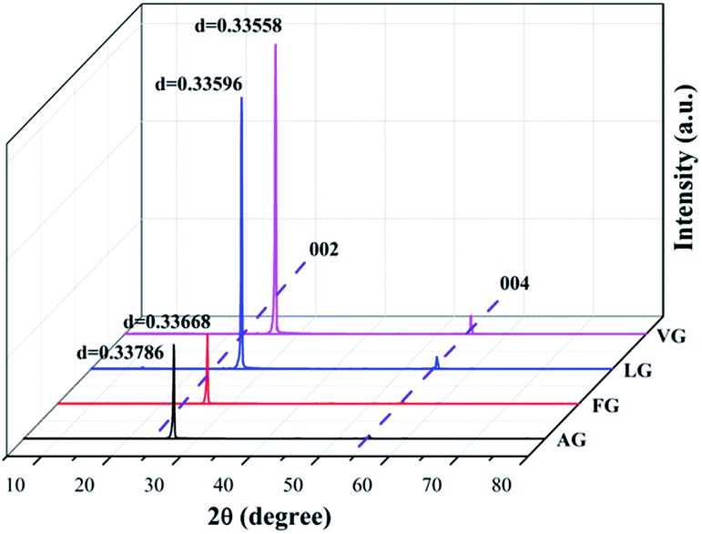 | ||
| Fig. 1 XRD spectra obtained for VG, LG, FG, and AG. | ||
The results for the degree of graphitization were 97.91% for VG, 93.48% for LG, 85.12% for FG and 71.39% for AG, indicating that there was a increasing trend in the crystalline morphology against ideal graphite from AG to VG. In addition, it was obvious that graphite with a high degree of graphitization presented peaks with strong intensity in the XRD spectrum, which indicates that the graphite possessed a superior crystal structure and thereby better diffraction.
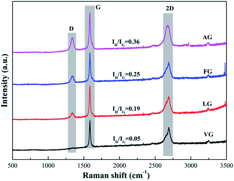
The Raman spectra of the natural graphites samples are shown in Fig. 2. The spectrum obtained for each sample showed the presence of D, G and 2D bands, located at approximately 1345, 1580 and 2670 cm−1, respectively. In addition, the lattice disorder of the graphite derivatives was usually evaluated by the ratio of the intensity of the D band to the G band (ID/IG).33 In addition, the values were determined to be 0.05 for VG, 0.19 for LG, 0.25 for FG and 0.36 for AG, implying that the degree of defects in the samples diminished in the order of the enhancement in the degree of graphitization.
 | ||
| Fig. 2 Raman spectra obtained for VG, LG, FG, and AG. | ||
The XPS spectra of the different graphite powders are shown in Fig. 3. Only two intense and distinct peaks at around 283.8 and 531.3 eV were observed, which were attributed to the high purity of the graphite, corresponding to the C 1s and O 1s peaks, respectively.34 Furthermore, the other weak peaks at approximately 151.1 eV could be related to Si 2s caused by a tiny amount of impurity.35 On the basis of the results obtained via XPS for the surface atomic concentration, the mass ratio of C and O could be obtained and reflected the existence of other oxides. In addition, the values of C/O were 75.78 for VG, 71.43 for LG, 61.48 for FG and 55.97 for AG, suggesting that a higher value of C/O represented less oxygen-containing functional groups and a lower degree of defects, as well as a higher degree of graphitization, which was in good agreement with the XRD and Raman results.
 | ||
| Fig. 3 XPS spectra obtained for VG, LG, FG, and AG. | ||
3.2. Characterization of GO and rGO
Fig. 4 shows the XRD spectra of the GO and rGO samples synthesized from the natural graphites with different degrees of graphitization. The characteristic diffraction peaks of the GO samples corresponding to the (002) plane were observed at 2θ = 10° with an average d-spacing of around 0.79 nm, as shown in Fig. 4a. The results indicated that the interlayer spacing was extended due to the intercalation of the oxygen-containing functional groups into the layers, damaging the original crystals of the natural graphite samples.36 In addition, the characteristic peaks observed for the (002) reflection planes of graphite at 2θ = 26.53° decreased in intensity; its was notable that the peak observed for GO-AG had almost disappeared, while that of GO-VG, GO-LG and GO-FG still existed with diminishing intensity, opposite to the increasing order observed for the degree of graphitization.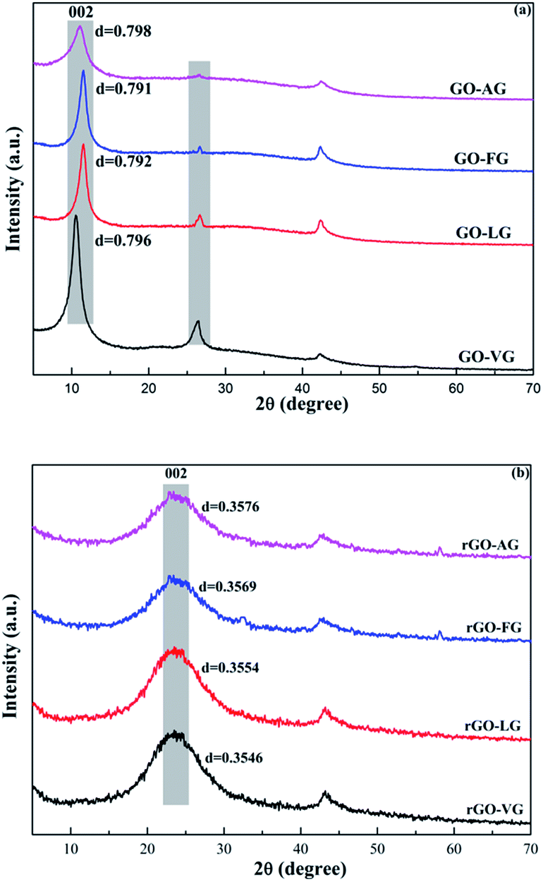 | ||
| Fig. 4 XRD patterns obtained for the as-prepared GOs (a) and rGOs (b). | ||
From the XRD patterns of the rGO samples displayed in Fig. 4b, dominant and broad peaks at approximately 2θ = 24.5° were observed with a d-spacing of around 0.36 nm, which indicated a slight difference when compared to the natural graphite samples (0.336 nm). These findings demonstrated that the crystalline structure can be restored after the reduction process used to synthesize few-layer graphene. In addition, the d-spacing of the (002) plane of the rGO samples prepared from the graphites with various degrees of graphitization showed negligible differences.
The FT-IR spectra obtained for the GO and rGO samples are shown in Fig. 5. For the spectra recorded for the GO samples, distinct and strong peaks were observed at approximately 3440–3200 cm−1 as a result of the –OH stretching vibrations of the hydroxyl groups.37 The peaks located at around 1724 cm−1 were ascribed to the C![[double bond, length as m-dash]](https://www.rsc.org/images/entities/char_e001.gif) O stretching vibrations of the carbonyl and carboxylic groups.38 In addition, the peaks located at around 1619 and 1400 cm−1 were attributed to the CC stretching mode of the non-oxidized graphitic domains and the deformation vibration of tertiary C–OH groups, respectively.39 Moreover, the peaks centered at 1224 cm−1 were related to the stretching vibrations of C–O–C and C–O at 1063 cm−1.40 In general, the adsorption peaks of the oxygen-containing functional groups exposed on the edges were nearly the same in terms of peak location and intensity after the oxidation process.
O stretching vibrations of the carbonyl and carboxylic groups.38 In addition, the peaks located at around 1619 and 1400 cm−1 were attributed to the CC stretching mode of the non-oxidized graphitic domains and the deformation vibration of tertiary C–OH groups, respectively.39 Moreover, the peaks centered at 1224 cm−1 were related to the stretching vibrations of C–O–C and C–O at 1063 cm−1.40 In general, the adsorption peaks of the oxygen-containing functional groups exposed on the edges were nearly the same in terms of peak location and intensity after the oxidation process.
 | ||
| Fig. 5 FT-IR spectra obtained for the as-prepared GrOs (a) and rGOs (b). | ||
Fig. 5b presents the FT-IR patterns of the rGO samples after the chemical reduction process. The peaks at 3440–3200 cm−1 observed for the –OH stretching vibrations changed slightly. In addition, the intensities of the peaks at 1724 cm−1 corresponding to the CO stretching vibrations, at 1400 cm−1 corresponding to C–OH deformation vibrations and at 1224 cm−1 corresponding to the C–O–C stretching vibrations were significantly reduced. On the contrary, the intensities of the peaks at 1063 cm−1 due to the C–O stretching vibrations increased significantly, implying that the chemical reduction process could effectively promote the process of removing the hydroxyl and carboxyl functionalities.
The Raman spectra of the GO and rGO powders prepared from the four types of graphite are shown in Fig. 6. Two predominant and remarkable peaks corresponding to the D-band at around 1350 cm−1 and G-band at around 1595 cm−1 were observed due to the breathing mode of the k-point phonons with A1g symmetry and first order scattering of the E2g phonons, respectively.41,42 On the basis of Raman analysis, the values of ID/IG were calculated to be 0.78 for GO-VG, 0.89 for GO-LG, 0.93 for GO-FG and 0.96 for GO-AG. In addition, the crystallite size (La) was used to assess the average size of the adjacent carbon atoms in the GO and rGO samples in the contiguous region and was able to be estimated according to the following equation.
| La = 44 × (ID/IG)−1 | (3) |
 | ||
| Fig. 6 Raman spectra obtained for the as-prepared GrOs (a) and rGOs (b). | ||
Based on the ID/IG results, the corresponding values of La were 55.70 nm for GO-VG, 52.38 for GO-LG, 47.31 for GO-FG and 45.83 for GO-AG, indicating that a high degree of graphitization corresponds to a relatively low degree of defects, and the incremental order of the in-plane sp2 domains of GO-AG, GO-FG, GO-LG and GO-VG was obtained. Furthermore, the defects are closely related to the degree of oxidation, meaning that the GO samples prepared from the graphites with a low degree of graphitization contained more oxygen-containing functional groups.
With regard to the Raman spectra obtained for the rGO samples, the intensities of the D-bands became stronger, while the intensities of the G-bands became weaker. The locations of the two bands displayed a small shift, implying that some of the defects were repaired during the chemical reduction process. In addition, the ID/IG values were 1.21 for rGO-VG, 1.24 for rGO-LG, 1.28 for rGO-FG and 1.31 for rGO-AG, indicating that the chemical reduction process can effectively remove the oxygen-containing functional groups at the edge of the rGO samples, however, the process may also induce more defects to be formed.43 The values of La were calculated to be 36.36, 35.48, 34.38 and 33.59 for rGO-VG, rGO-LG, rGO-FG and rGO-AG, respectively, showing a diminishing sequence for the in-plane sp2 domains from rGO-VG to rGO-AG.
Fig. 7a and b present the representative AFM images and cross-section analysis along the lines in the AFM images for the individual sheets of the as-prepared rGO samples. The typical thickness obtained from the AFM images was approximately 0.781 nm for rGO-VG, 0.750 nm for rGO-LG, 0.686 nm for rGO-FG and 0.625 nm for rGO-AG, which are in good agreement with that reported for rGO.44 The thickness values were slightly greater than that observed for ideal graphene, whose thickness was around 0.335 nm, which was attributed to the presence of carboxyl and hydroxyl groups on the edges of the rGO sheets.45–47 After counting three hundred rGO sheets, the thickness distribution was obtained, as shown in Fig. 7c, with the majority of all the rGOs thicknesses measuring less than 2 nm. Moreover, the thickness of sheets less than 1 nm occupied 30.16% for rGO-VG, 35.64% for rGO-LG, 41.36% for rGO-FG, and 49.89% for rGO-AG, indicating that the natural graphites with a low degree of graphitization were more suitable to synthesize less-layered rGO.
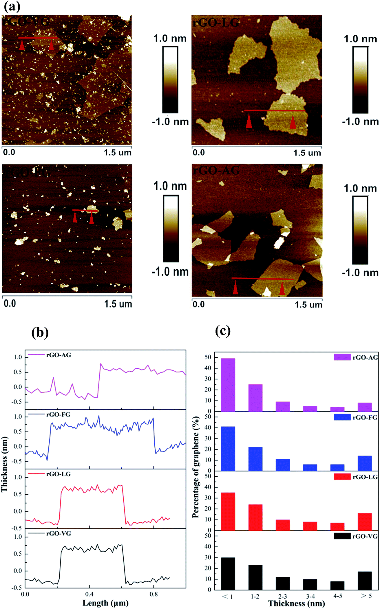 | ||
| Fig. 7 AFM images (a), corresponding height profiles (b) and thickness distribution histograms (c) obtained for the as-prepared rGOs (c). | ||
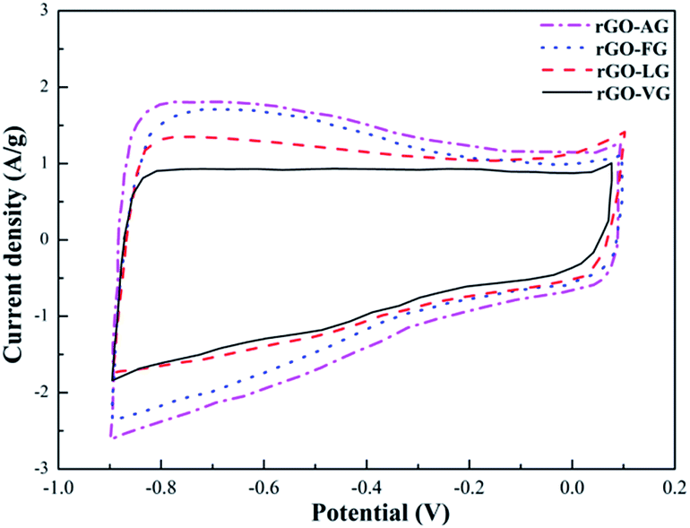
Fig. 8 shows the CV curves of the as-prepared rGO samples. In general, there was little difference between the four curves, all of which seemed to form nearly rectangular and relatively symmetrical shapes. Nevertheless, weak faradaic peaks were observed, suggesting that a few redox reactions took place, which were attributed to some oxygen-containing functional groups remaining in the rGO samples.48 In addition, based on the equation, the specific capacitance values can be obtained as 107.53 F g−1 for rGO-VG, 115.17 F g−1 for rGO-LG, 126.98 F g−1 for rGO-FG and 139.15 F g−1 for rGO-AG, which were ascribed to the degree of redox in the rGOs impacting the defects and microstructure of the graphite samples with different degrees of graphitization.
 | ||
| Fig. 8 CV curves obtained for the as-prepared rGOs. | ||
3.3. Mechanism
The oxidation, exfoliation and reduction process of the as-prepared rGO samples may cause the differences observed in our results, as presented in Fig. 9. It was obvious that the different degrees of graphitization on graphite can lead to the different structures, degree of defect, thickness and specific capacitance of the rGO samples through different redox and exfoliation routes on account of the analysis described above. As is known to all, graphite with a low degree of graphitization contains more active carbon atoms on the edges of the graphitic layers and the numerous carbon atoms exposed on the layers can increase the d-spacing and the degree of defects in the graphite starting material. Due to the fact that it was more likely for the exposed carbon atoms to be attacked during the oxidation process, graphites with lower degrees of graphitization undergo oxidation and exfoliation more easily. In addition, the greater d-spacing of poorly crystallized graphite results in a weak interaction between the carbon interlayers, which promotes the intercalation and diffusion of the oxidants.49 In addition, the defects that exist in the graphite structure can shorten the route for the diffusion of oxidants, enabling the process to be facile and effective. From the schematic representation shown in Fig. 9, natural graphites with a low degree of graphitization, high degree of defect and low C/O values are able to form well-oxidized products under similar conditions with excellent exfoliation results to obtain two-layer or less graphene after reduction, which is in accordance with the characteristic (002) peaks of graphite at 2θ = 26° in the XRD patterns of GO-AG and GO-FG almost disappearing and the formation of thick layer graphene as-observed by AFM. | ||
| Fig. 9 Schematic process for the oxidation, exfoliation and reduction of the preparation of the rGOs. | ||
4. Conclusions
Based on the characterization analysis, the results were that the degree of defects in VG, LG, FG and AG present a diminishing sequence, while the degree of graphitization and C/O values on the surface of the four types of natural graphites increased gradually. The experimental results indicate that it was more likely for graphite with a low degree of graphitization to be sufficiently oxidized for the preparation of GO and form the thinnest layer of graphene after the reduction process. In addition, rGO synthesized using graphite with the lowest degree of graphitization has the most defects and the smallest size of in-plane sp2 domains, possessing high quality with a specific capacitance of 139.15 F g−1. The results can be attributed to the fact that most of the defects showed optimal activity and high ID/IG values as well as relatively low La values, resulting in the small size of the in-plane sp2 domains. The smaller the size of the in-plane sp2 domains, the faster the electrons can transfer and the ion exchange taking place at the interface between the electrode and electrolyte is accelerated, resulting in the high specific capacitance observed in the electrochemical measurements. The investigations carried out in this study have established a theoretical basis to select a suitable natural graphite starting material based on the performance and characteristic properties of the graphene required for a particular application.Conflicts of interest
There are no conflicts to declare.Acknowledgements
The financial support for this work provided by the Fundamental Research Funds for the Central Universities (WUT: 2017zy073) is gratefully acknowledged.References
- P. Solís-Fernández, R. Rozada, J. I. Paredes, S. Villar-Rodil, M. J. Fernández-Merino, L. Guardia, A. Martínez-Alonso and J. M. D. Tascón, J. Alloys Compd., 2012, 536, S532–S537 CrossRef.
- W.-J. Peng, H.-Q. Li, Y.-Y. Liu and S.-X. Song, J. Mol. Liq., 2017, 230, 496–504 CrossRef CAS.
- M. Agharkar, S. Kochrekar, S. Hidouri and M. A. Azeez, Mater. Res. Bull., 2014, 59, 323–328 CrossRef CAS.
- A. K. Geim and K. S. Novoselov, Nat. Mater., 2017, 6, 183–191 CrossRef PubMed.
- R. K. Joshi, S. Alwarappan, M. Yoshimura, V. Sahajwalla and Y. Nishina, Appl. Mater. Today., 2015, 1, 1–12 CrossRef.
- E. P. Randviir, D. A. C. Brownson and C. E. Banks, Mater. Today, 2014, 17, 426–432 CrossRef CAS.
- S. Hermanová, M. Zarevúcká, D. Bousa, M. Mikulics and Z. Sofer, Appl. Mater. Today, 2016, 5, 200–208 CrossRef.
- J.-H. Zhu, M.-J. Chen, Q.-L. He, L. Shao, S.-Y. Wei and Z.-H. Guo, RSC Adv., 2013, 3, 22790–22824 RSC.
- H. A. Becerril, J. Mao, Z. Liu, R. M. Stoltenberg, Z. Bao and Y. Chen, ACS Nano, 2008, 2, 463–470 CrossRef CAS PubMed.
- J. Wu, W. Pisula and K. Müllen, Chem. Rev., 2007, 107, 718–747 CrossRef CAS PubMed.
- C. Berger, Z. Song, X. Li, X. Wu, N. Brown, C. Naud, D. Mayou, T. Li, J. Hass and A. N. Marchenkov, Science, 2006, 312, 1191–1196 CrossRef CAS PubMed.
- L.-Y. Jiao, L. Zhang, X.-R. Wang, G. Diankov and H.-J. Dai, Nature, 2009, 458, 877–880 CrossRef CAS PubMed.
- P. W. Sutter, J. I. Flege and E. A. Sutter, Nat. Mater., 2008, 7, 406–411 CrossRef CAS PubMed.
- Z. Bo, K.-H. Yu, G.-H. Lu, P.-X. Wang, S. Mao and J.-H. Chen, Carbon, 2011, 49, 1849–1858 CrossRef CAS.
- S. Stankovich, D. A. Dikin, R. D. Piner, K. A. Kohlhaas, A. Kleinhammes, Y.-Y. Jia, Y. Wu, S. T. Nguyen and R. S. Ruoff, Carbon, 2007, 45, 1558–1565 CrossRef CAS.
- Y. Hu, S.-X. Song and A. Lopez-Valdivieso, J. Colloid Interface Sci., 2015, 450, 68–73 CrossRef CAS PubMed.
- C. K. Chua and M. Pumera, Chem. Soc. Rev., 2014, 43, 291–312 RSC.
- A. K. Sarker and J. D. Hong, Colloids Surf., A, 2013, 436, 967–974 CrossRef CAS.
- Q.-Q. Zhuo, J. Gao, M.-F. Peng, L.-L. Bai, J.-J. Deng, Y.-J. Xia, Y.-Y. Ma, J. Zhong and X.-H. Sun, Carbon, 2013, 52, 559–564 CrossRef CAS.
- W.-J. Peng, H.-Q. Li, Y. Hu, Y.-Y. Liu and S.-X. Song, Mater. Res. Bull., 2016, 74, 333–339 CrossRef CAS.
- Z.-S. Wu, W.-C. Ren, L.-C. Gao, B.-L. Liu, C.-B. Jiang and H.-M. Cheng, Carbon, 2009, 47, 493–499 CrossRef CAS.
- X. Jiao, L.-Y. Zhang, Y.-S. Qiu and J.-F. Guan, Colloids Surf., A, 2017, 529, 292–301 CrossRef CAS.
- N. Iwashita, M. Inagaki and Y. Hishiyama, Carbon, 1997, 35, 1073–1077 CrossRef CAS.
- H.-J. Yang, S. H. Yoon, Y. Korai, I. Mochida and O. Katou, Carbon, 2003, 41, 397–403 CrossRef CAS.
- S. Lim, A. S. Yoon, I. Mochida and J.-H. Chi, J. Phys. Chem. B, 2004, 108, 1533–1536 CrossRef CAS.
- C. Botas, P. Álvarez, C. Blanco, R. Santamaría, M. Granda, P. Ares, F. Rodríguez-Reinoso and R. Menéndez, Carbon, 2012, 50, 275–282 CrossRef CAS.
- C. H. A. Wong, Z. Sofer and M. Pumera, Chem.–Eur. J., 2015, 21, 8435–8440 CrossRef CAS PubMed.
- H. L. Poh, F. Sanek, A. Ambrosi, G.-J. Zhao, Z. Soferb and M. Pumera, Nanoscale, 2012, 4, 3515–3522 RSC.
- W.-J. Peng, H.-Q. Li, Y.-Y. Liu and S.-X. Song, Appl. Surf. Sci., 2016, 364, 620–627 CrossRef CAS.
- J.-L. Liu, J.-Q. Gao, J.-K. Cheng, J.-F. Yang and G.-J. Qiao, Diamond Relat. Mater., 2006, 15, 117–120 CrossRef CAS.
- L.-H. Zou, B.-Y. Huang, Y. Huang, Q.-Z. Huang and C.-A. Wang, Mater. Chem. Phys., 2003, 82, 654–662 CrossRef CAS.
- H. Fujimoto, Carbon, 2010, 48, 3446–3453 CrossRef CAS.
- Z.-S. Wu, W.-C. Ren, L.-B. Gao, J.-P. Zhao, Z.-P. Chen, B.-L. Liu, D.-M. Tang, B. Yu, C.-B. Jiang and H.-M. Cheng, ACS Nano, 2009, 3, 411–417 CrossRef CAS PubMed.
- X. Jiao, L.-Y. Zhang, Y.-S. Qiu and Y.-R. Yuan, RSC Adv., 2017, 7, 38350–38359 RSC.
- Y.-F. Cai, Y.-G. Pan, J.-Y. Xue, Q.-F. Sun, G.-Z. Su and X. Li, Appl. Surf. Sci., 2009, 255, 8750–8760 CrossRef CAS.
- Q.-Q. Zhuo, J. Gao, M.-F. Peng, L.-L. Bai, J.-J. Deng, Y.-J. Xia, Y.-Y. Ma, J. Zhong and X.-H. Sun, Carbon, 2013, 52, 559–564 CrossRef CAS.
- G. I. Titelman, V. Gelman, S. Bron, R. L. Khalfin, Y. Cohen and H. Bianco-Peled, Carbon, 2005, 43, 641–649 CrossRef CAS.
- T. A. Saleh, A. A. Al-Saadi and V. K. Gupta, J. Mol. Liq., 2014, 191, 85–91 CrossRef CAS.
- C. Nethravathi and M. Rajamathi, Carbon, 2008, 46, 1994–1998 CrossRef CAS.
- X.-W. Cui, X. Yu, L. Hou, A. Gagnoud, Y. Fautrelle, R. Moreau, Z.-M. Ren, X.-G. Lu and X. Li, J. Alloys Compd., 2016, 684, 21–28 CrossRef CAS.
- Q.-L. Huang, J.-M. Wang, W.-X. Wei, Q.-X. Yan, C.-L. Wu and X.-S. Zhu, J. Hazard. Mater., 2015, 83, 123–130 CrossRef PubMed.
- S.-C. Lu, M.-G. Yao, X.-G. Yang, Q.-J. Li, J.-P. Xiao, Z. Yao, L.-H. Jiang, R. Liu, B. Liu, S.-L. Chen, B. Zou, T. Cui and B.-B. Liu, Chem. Phys. Lett., 2013, 585, 101–106 CrossRef CAS.
- F.-P. Yin, S. Wu, Y.-B. Wang, L. Wu, P.-L. Yuan and X. Wang, J. Solid State Chem., 2016, 237, 57–63 CrossRef CAS.
- P. Solís-Fernández, J. I. Paredes, S. Villar-Rodil, A. Martínez-Alonso and J. M. D. Tascón, Carbon, 2010, 48, 2657–2660 CrossRef.
- A. Palinkas, G. Molnar, C. Hwang, L. P. Biro and Z. Osvath, RSC Adv., 2016, 6, 86253–86258 RSC.
- H. C. Schniepp, J. L. Li, M. J. McAllister, H. Sai, M. Herrera-Alonso, D. H. Adamson, R. K. Prud'homme, R. Car, D. A. Saville and I. A. Aksay, J. Phys. Chem. B, 2006, 110, 8535–8539 CrossRef CAS PubMed.
- M. J. McAllister, J. L. Li, D. H. Adamson, H. C. Schniepp, A. A. Abdala, J. Liu, M. Herrera-Alonso, D. L. Milius, R. Car, R. K. Prud'homme and I. A. Aksay, Chem. Mater., 2007, 19, 4396–4404 CrossRef CAS.
- Z. Lin, Y. Liu, Y. Yao, O. J. Hildreth, Z. Li, K. Moon and C.-P. Wong, J. Phys. Chem. C, 2011, 115, 7120–7125 CAS.
- G. Shao, Y. Lu, F. Wu, C. Yang, F. Zeng and Q. Wu, J. Mater. Sci., 2012, 47, 4400–4409 CrossRef CAS.
| This journal is © The Royal Society of Chemistry 2017 |