DOI:
10.1039/C7RA10808G
(Paper)
RSC Adv., 2017,
7, 55450-55458
Process simulation of coal-direct chemical looping gasification for syngas production
Received
30th September 2017
, Accepted 28th November 2017
First published on 7th December 2017
Abstract
The coal gasification process is used in the commercial production of syngas as a means toward the clean use of coal. In this paper, the process of syngas production via the coal-direct chemical looping gasification process (CDCLG) is modeled under thermochemical equilibrium with the Gibbs free energy approach, and the model is developed using a complete and comprehensive simulation model. Due to the kinetic limits of char gasification, the carbon conversion efficiency is not suggested to be larger than 0.9 in the fuel reactor during the CDCLG process. Besides, the simulation results suggest the residual carbon should be burnt in the air reactor. Moreover, the effects of various conditions, which include carbon conversion, temperature, pressure and the steam feed ratio, on the input and energy output parameters, including the air feed ratio, efficiency of electricity and syngas quality, are studied and revealed in this paper.
1. Introduction
Syngas, one of the most important energy carriers in sustainable energy systems, can be produced from carbonaceous materials, such as natural gas, oil, coal and biomass.1–3 From these mentioned energy sources, coal has been regarded as the most attractive option, due to its relative rich abundance and low cost. Hydrogen has already been generated from coal via centralizing gasification processes, in which the coal is first partially oxidized to syngas.4,5 Fuel gas with a higher H2 concentration can be produced via steam–char gasification, which attracts much research interest. Additionally, more highlights can be found in the steam gasification process, such as maximizing gas productivity with a high heating rate, advantageous residence time and high char reduction efficient. However, steam gasification reactions are highly endothermic. To provide the necessary heat input, air is introduced to burn parts of the available fuels (char and gas). This favors the dilution with nitrogen of the product gas and reduces its caloric value. A number of researchers have studied the use of metal oxides for providing the heat, among which the exothermic reaction between CuO and carbon results in copper oxide being one of the most popular replacements. Also, CuO has been proven to be an oxygen releasing material,6,7 which can contribute to kinetic improvement of the reaction between CuO and carbon.8
Chemical looping combustion and gasification (CLC&G9) has been suggested to be the most promising technology, which combines the inherent separation of CO2 with a reduced energy penalty.10–12 Oxygen carriers (OC) and replacing air are used as the oxygen source to prevent mixing nitrogen with the CO2 stream.
Different chemical looping configurations have been studied by Andersen et al.13 and Ertesvåg et al.14 Consonni and Viganò15 analyzed a pre-combustion setup to co-generate power and hydrogen. Besides, simulation software has been widely employed to investigate the utilization of chemical looping strategies in coal gasification processes, such as optimizing syngas productivity, energy balances, the circulation rates of oxygen carriers, the oxygen carrier mass loadings, the carbon burnout, the oxygen partial pressure, etc.16–18. The coal-direct chemical looping gasification (CDCLG) system is a promising technology for capturing post-combustion CO2 from power plants, in which the fuel reactor is regarded as the gasifier, producing syngas, and the air reactor is the combustor in the gasification process. In this study, the kinetics of char-CO2 gasification are studied in a pressurized thermo-gravimetric analyzer (TGA-HP150S) before simulation. Then the integration of a chemical looping concept and partial-gasification-combustion is evaluated using simulation software. Notably, we focused on a new configuration of chemical looping gasification, which featured high but not full carbon conversion in the fuel reactor, with residual carbon then being combusted in the air reactor. We proposed that the char residue should be removed from the gasification stage and considered in the combustion stage for the continuation of carbon conversion.
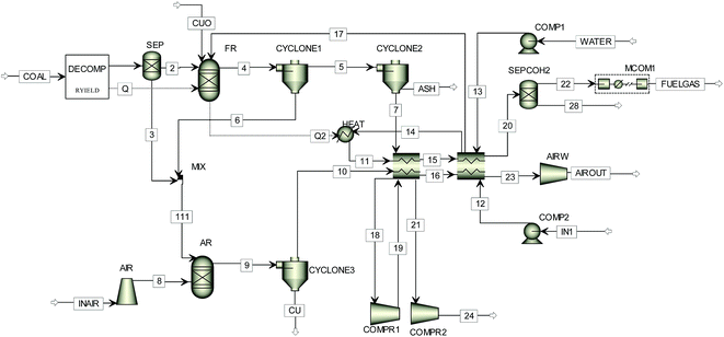
2. Process descriptions
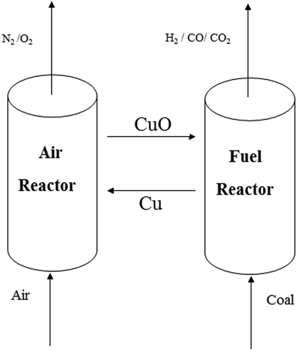
A schematic diagram of the chemical looping system is shown in Fig. 1. There are two main reactors in this system, i.e., a fuel reactor and an air reactor. The major reactions (with CuO as the oxygen carrier) in the fuel reactor are listed as follows:| | |
C + H2O → CO + H2, +131.5 kJ mol−1
| (1) |
| | |
C + CO2 → 2CO, +172 kJ mol−1
| (2) |
| | |
CH4 + H2O → CO + 3H2, +206 kJ mol−1
| (3) |
| | |
CuO → 1/2Cu2O + 1/4O2, +327 kJ mol−1
| (4) |
| | |
C + 2H2 → CH4, −74.8 kJ mol−1
| (5) |
| | |
CO + H2O → CO2 + H2, −41 kJ mol−1
| (6) |
| | |
C + O2 → 2CO, −110.3 kJ mol−1
| (7) |
| | |
CuO + CO → Cu + CO2, −134.3 kJ mol−1
| (8) |
| | |
CuO + H2 → Cu + H2O, −128.8 kJ mol−1
| (9) |
| | |
4CuO + CH4 → CO2 + 4Cu + 2H2O, −314.6 kJ mol−1
| (10) |
| | |
2CuO + C → 2Cu + CO2, −96.5 kJ mol−1
| (11) |
| | |
2Cu2O + C → 4Cu + CO2, −61 kJ mol−1
| (12) |
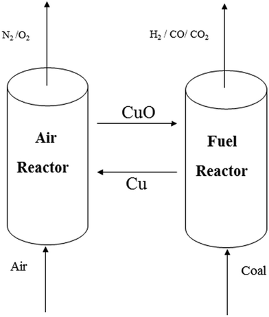 |
| | Fig. 1 A simplified flow diagram for the coal-direct chemical looping process. | |
Aiming to simplify the explanation, just the parts of the reactions involved into the thermodynamic calculations are listed here. Furthermore, coal is considered as pure carbon in these reactions. Meanwhile, hydrogen and other combustible or gaseous constituents have also been considered in the thermodynamic calculations.19
Heat balance requires the highly endothermic reactions (1)–(4) to occur in the fuel reactor; the air reactor has a higher temperature than that of the fuel reactor. Therefore, the oxygen carrier solids bring extra heat to maintain the necessary heat for the gasification stage. Moreover, reactions (8)–(12) are applied to supply the reaction heat; these reactions have exothermic properties and occur when feeding oxygen carriers into the fuel reactor.
In the air reactor, the reduced oxygen carrier is fully reoxidized to CuO according reactions (13) and (14). These oxidation reactions generate a large amount of heat; as a result, the oxygen carrier in the air reactor has a higher temperature compared with the temperature in the fuel reactor. The air fed into the air reactor is not only the oxidizing agent for the reduced oxygen carrier and residual carbon, but also the heat carrier to maintain the temperature of the air reactor. The heat carried by the flue gas can be utilized for steam and electricity generation.
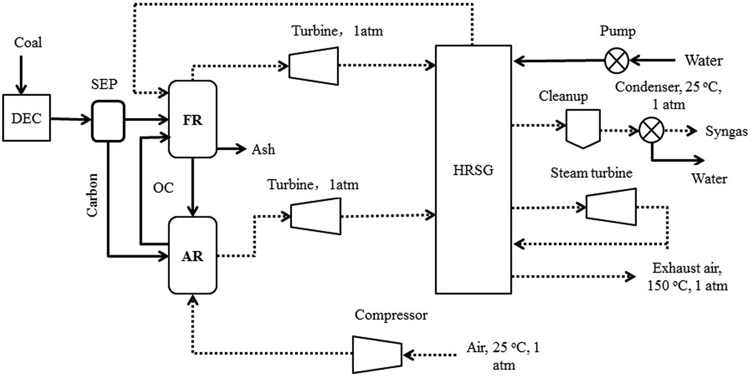
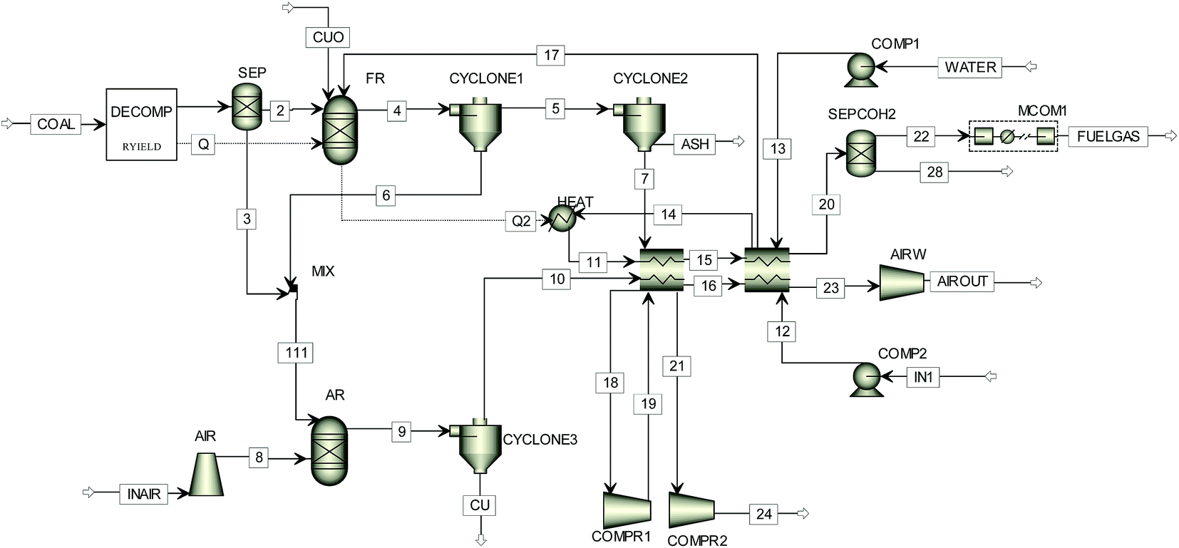
In order to simulate the reaction steps occurring in the CDCLG process, the Aspen Plus software package is adopted.18,20,21 The flow chart of simulation for the process is sketched in Fig. 2. The whole system consists of two RGibbs chemical-equilibrium reactor models,19 and includes a fuel reactor and an air reactor. The fuel reactor is composed of a pyrolyzer, a carbon separator and a gasifier. PR-BM methods are used to determine the properties of conventional components, while the HCOALGEN and DCOALIGT methods are employed for nonconventional components,17,20,22 such as coal and ash. PR-BM physical properties are also used to calculate the energies of the compressor and turbine, through which the polytrophic efficiency is assumed to be equal to 72%. The simulation model for the CDCLG process is shown in Fig. 3, and the key units used in the simulation models are given in Table 1.
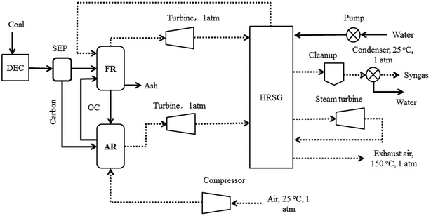 |
| | Fig. 2 A process flow diagram of the CDCLG process for syngas production. | |
 |
| | Fig. 3 The simulation model used for simulating the coal-direct chemical looping gasification process. | |
Table 1 Simulation models for the key units
| Unit operation |
Model |
| Pyrolyzer |
RYield |
| Gasifier |
RGibbs |
| Air reactor |
RGibbs |
| Pressure changers |
Pump, compr, Mcompr |
| Heat exchangers |
Heater, MheatX |
| Mixers/splitters/separators |
Mixer/cyclone/sep |
The coal is sent to the pyrolyzer after its pulverization, where the coal is decomposed into its constituent elements based on the ultimate analysis. Then the mixture is introduced to the fuel reactor and reacted with oxygen carrier particles (CuO, with Al2O3 for inert support), and the oxygen carrier particles are circulated between the fuel reactor and air reactor. The steam that is generated from the compressed water using the process heat is used as the gasification agent, which is required in the fuel reactor. The air reactor is supplied with air by a compressor working at the inlet pressure.
The excess heat from the system can be recovered using the exhaust gas streams or by the embedded heat exchangers in the reactors. A significant amount of the heat will be carried by the flue gas from the air reactor. Such high temperature flue gas can be potentially utilized in an expander or in heat recovery steam generation (HRSG) by introducing the resulting syngas to the flue gas. In the CDCLG process, the chemical energy of coal is converted into syngas, heat and electricity products. Therefore, the syngas yield tends to increase with a decrease in the net heat generation and a decrease in the following net electricity generation, and there is a balance between syngas, net heat and net electricity generation.
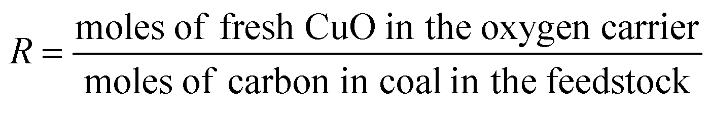
For the better presentation of the simulation conditions and results, several parameters, such as the oxygen carrier feed ratio (R), efficiency of electricity (η), syngas production capacity, and efficiency of electricity based on the emission of CO2 from the air reactor (x and y, respectively), have been defined in the following equations. It should be noted that the flow rate of gas (H2, CO, CH4 and CO2) is based on the mass feed ratio of coal, and the yield of syngas refers to the total amount of H2 and CO.
| |
 | (15) |
| |
 | (16) |
| |
 | (17) |
| |
 | (18) |
3. Operating conditions
Proximate and ultimate analyses of the coal used in this simulation are summarized in Table 2.
Table 2 Proximate and ultimate analysis of the coal used
| |
Proximate analysis |
Ultimate (as dry) |
| Moisture |
Fixed carbon |
Volatiles |
Ash |
C |
H |
N |
O |
S |
| Coal |
10.20 |
44.65 |
35.35 |
9.80 |
71.72 |
5.06 |
1.46 |
7.75 |
2.82 |
| HHV (MJ kg−1) |
27.134 |
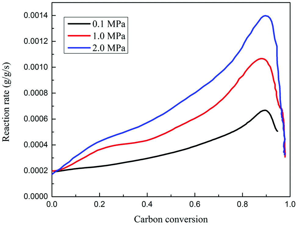
Char gasification has been reported to be a rate-determining process. Due to its kinetic limit, it is difficult to keep the char gasification process going in the final stages. The kinetics of char-CO2 gasification are analyzed consecutively using a pressurized thermo-gravimetric analyzer (TGA-HP150S) at 0.1–2.0 MPa, 900 °C, and under 100% (mole ratio) CO2. The TGA-HP150S model is specially configured for gasification and related studies.23,24 It includes an integrated steam generator and a double-walled reaction chamber that allows for higher temperatures. The maximum weight capacity is 25 g. The weighing accuracy is ±0.0002%. The weighing precision is ±30 μg. The sensitivity is 10 μg. The upper temperature and pressure limit are 1200 °C and 5.0 MPa respectively. The relationship between the gasification rate and carbon conversion efficiency is shown in Fig. 4.
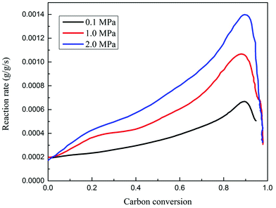 |
| | Fig. 4 The reaction rate versus carbon conversion during char gasification, at 100% mole CO2 and 950 °C, between 0.1 and 2.0 MPa. | |
It is observed that the gasification rate experienced an initially slow increase, then a rapid increase and finally a decrease, corresponding to the carbon conversion efficiency. The kinetics of char gasification finally dominated the determination of the threshold values for carbon conversion efficiencies between the fuel reactor and air reactor. Here, the optimal threshold value of the carbon conversion efficiency for the selected coal in this study is around 0.9, where further gasification of char residue is not suggested. In the following study on the effects of temperature, pressure and steam ratios on the process performance, the carbon conversion in the fuel reactor is set at 0.9, and the unconverted carbon is burned in the air reactor.
The coal processing capacity of the plant is specified to be 13![[thin space (1/6-em)]](https://www.rsc.org/images/entities/char_2009.gif) 267 kg h−1 (100 MW, HHV (Higher Heat Value)). In the simulation process, the oxygen carrier is composed of 60 wt% CuO and 40 wt% Al2O3. The operating conditions for the fuel reactor are set at a temperature of 750–950 °C and a pressure of 0.1–3.0 MPa, and the coal is dried (5% moisture content before entering the fuel reactor). For the air reactor, the temperature is set at 1000 °C and the pressure is 0.1–3.0 MPa. The gasifier is an isothermal reactor, and there are several approaches to balance the heat generation from the gasifier (ΔH < 0), such as: (1) the injection of a reasonable amount of steam into the gasifier; (2) combusting a portion of the coal; or (3) sending a certain fraction of reduced copper-oxides from the air reactor to the gasifier. The air reactor is an adiabatic reactor; in order to maintain the temperature, an amount of air, which is not only used for reacting with oxygen carriers and carbon, but also for carrying extra heat generated from the air reactor, should be fed into the air reactor.
267 kg h−1 (100 MW, HHV (Higher Heat Value)). In the simulation process, the oxygen carrier is composed of 60 wt% CuO and 40 wt% Al2O3. The operating conditions for the fuel reactor are set at a temperature of 750–950 °C and a pressure of 0.1–3.0 MPa, and the coal is dried (5% moisture content before entering the fuel reactor). For the air reactor, the temperature is set at 1000 °C and the pressure is 0.1–3.0 MPa. The gasifier is an isothermal reactor, and there are several approaches to balance the heat generation from the gasifier (ΔH < 0), such as: (1) the injection of a reasonable amount of steam into the gasifier; (2) combusting a portion of the coal; or (3) sending a certain fraction of reduced copper-oxides from the air reactor to the gasifier. The air reactor is an adiabatic reactor; in order to maintain the temperature, an amount of air, which is not only used for reacting with oxygen carriers and carbon, but also for carrying extra heat generated from the air reactor, should be fed into the air reactor.
4. Results and discussion
Baseline performance of the fuel reactor
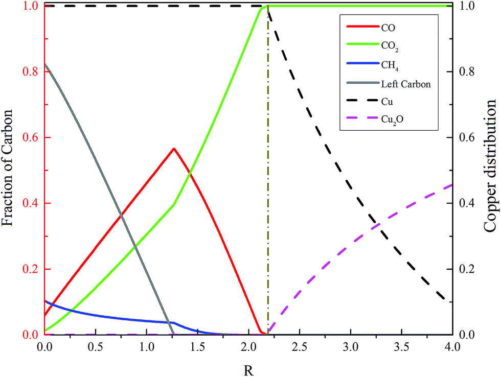
The simulation software sensitivity analysis is used to evaluate the fuel reactor performance under the baseline conditions, i.e., at 3.0 MPa and 850 °C. The ratio (R) between oxygen carrier and coal flow rate is varied. The simulation results are summarized in Fig. 5. It can be seen that the minimum ratio (R) for the coal to be fully oxidized into CO2 and H2O in the fuel reactor is 2.17. A higher R value means higher carbon conversion, as well as a higher CO2 concentration in the fuel gas, which is not preferred, because the fuel reactor is supposed to generate fuel gas. Thus, a reasonable oxygen carrier feed ratio must be maintained to keep an appropriate value of CO2 concentration in the fuel gas.
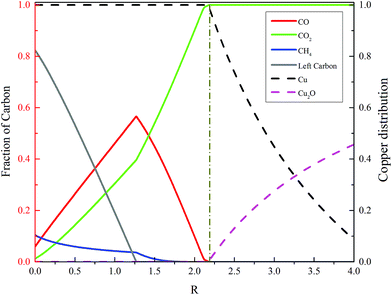 |
| | Fig. 5 Carbon distribution and copper oxide conversion under various CuO/coal flow rate ratios at 850 °C and 3.0 MPa in the fuel reactor. | |
The effects of temperature on the process performance
The fuel reactor temperature is a crucial factor for char gasification in interconnected fluidized beds.25 In the cases when the air reactor temperature is 1000 °C, the fuel reactor temperature is varied from 750 to 950 °C, the operating pressure is 2.0 MPa, the steam/carbon ratio is 0.8 and the value of R is 1.20. All these parameters are presented to demonstrate the effect of the fuel reactor temperature, and the simulation results are shown in Fig. 6.
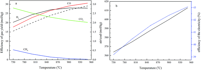 |
| | Fig. 6 The effects of temperature on the process performance (a) the effect of temperature on gas yield, dashed line: (CO + H2 + CH4)/CO2, and (b) the effect of temperature on the air ratio and efficiency of electricity generation. | |
The results in Fig. 6a show that the flow rates of H2 and CO increase upon increasing the temperature, CO2 and CH4 decrease as the temperature rises, and the ratio between the fuel gas (CO, H2 and CH4) and CO2 increases with the elevating of the temperature. They also indicate that the concentrations of H2 and CO increase as the fuel reactor temperature rises, whilst CO2 and CH4 decrease as the temperature increases. Moreover, the ratio between H2 and CO decreases with the temperature and the value of H2/CO is around 1.0 at 850 °C.
The composition of the gas yield from the fuel reactor is based on the combination of a series of complex and competing reactions, as given in reactions (1)–(10). The major reactions (1) and (2) of char gasification, and reactions (3) and (4) in the fuel reactor, are intensive endothermic process, while reactions (5)–(12) are exothermic reactions. A higher temperature is conducive to enrich the reactants in exothermic reactions and the products in endothermic reactions.25 Therefore, reactions (1)–(4) are strengthened with an increase in the fuel reactor temperature, which results in an increase of H2 and CO, and a decrease of CO2, and this trend is similar to the effects of temperature on the gas content, as described earlier.25 At a lower fuel reactor temperature, the H2 concentration is greater than that of CO, and the difference between the gases reduces as the fuel reactor temperature increases. Considering the importance of reactions (1) and (6), the presence of steam favors that reaction, leading to an increase in H2. Although reaction (6) also releases CO2 and consumes CO, the concentration of CO2 decreased and CO increased with a rise in temperature. A reasonable explanation is that reaction (2) consumes CO2 and becomes the dominant reaction, resulting in a CO increase and a CO2 decrease as the temperature rises.
There are two paths to using the gas generated from the fuel reactor: a gas turbine electricity generator and chemical production. A high CO2 concentration is not good for either of the paths; on the other hand, CH4 is advantageous for a gas turbine electricity generator, but not for chemical production. Additionally, the concentration of CO2 should be controlled at less than 30% in the gas generation from the fuel reactor, and for chemical production, the CH4 concentration should be small.
The effect of the fuel reactor temperature on the air feed ratio is shown in Fig. 6b. The air reactor is an adiabatic reactor, and the temperature is controlled via the air feed ratio, the temperature of the oxygen carriers from the fuel reactor, and the reaction heat generated from the reactions between Cu, carbon and O2. The higher operational temperature in the fuel reactor means the oxygen carriers fed into the air reactor have a higher temperature, so more air should be added into the air reactor to take away the heat from the air reactor. In this study, heat exchangers, heat recovery steam generators, and optional high pressure gas expanders are configured to extract energy from the high temperature exhaust gas streams produced by the CDCLG reactors.
Fig. 6b also shows that the efficiency of electricity generation (η) decreases with an increase in the operational temperature. A higher temperature leads to more fuel gas (CO, H2 and CH4) generation, and more energy in the coal being converted to the higher heating value of the fuel gas product.
The effects of pressure on the process performance
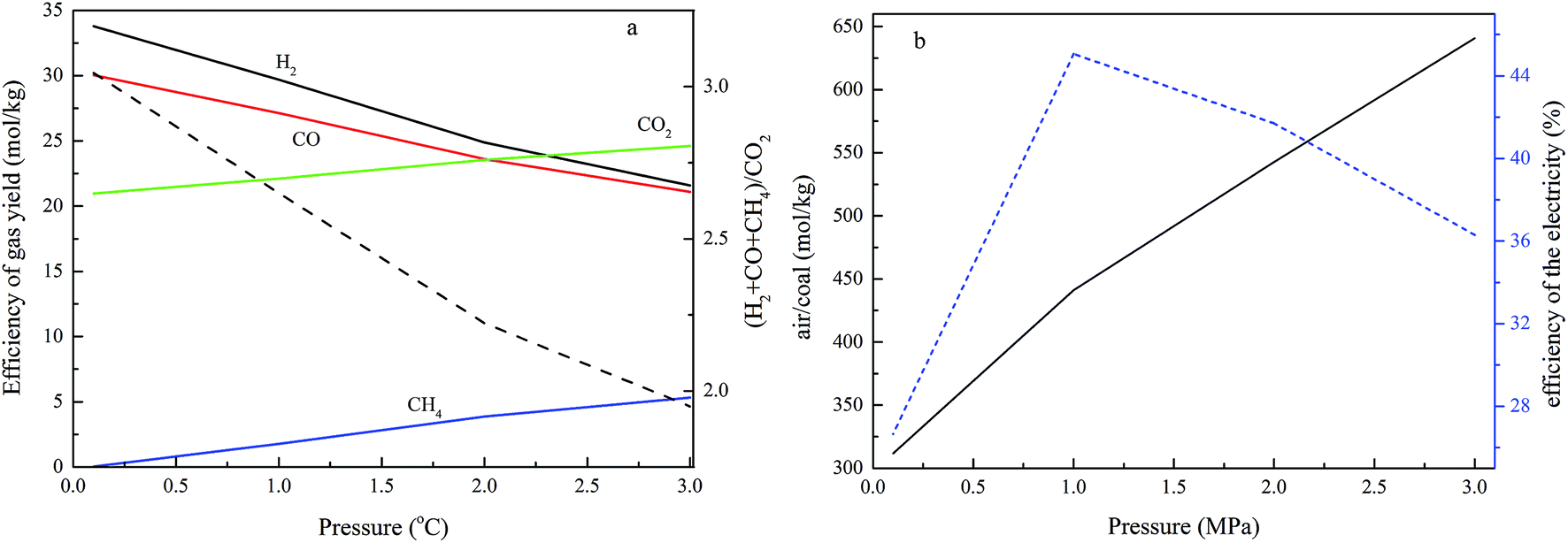
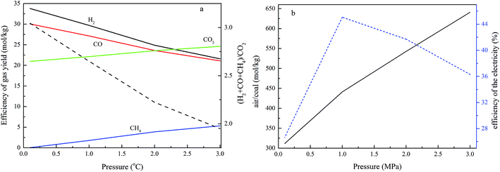
The operational pressure is another crucial factor for char gasification in interconnected fluidized beds. In this case, the air reactor temperature is 1000 °C, the fuel reactor temperature is 800 °C, the operating pressure varied from 0.1 MPa to 3.0 MPa, the ratio between steam and carbon is 0.6, R is 1.11%, and the carbon conversion in the fuel reactor is set at 0.9. The results are presented to demonstrate the effect of pressure on the process performance, and are given in Fig. 7.
 |
| | Fig. 7 The effect of pressure on the process performance (a) the effect of pressure on the gas yield, dashed line: (CO + H2 + CH4)/CO2, and (b) the effect of pressure on the air ratio and efficiency of electricity generation. | |
The results in Fig. 7a show that the flow rates of H2 and CO decrease as the pressure increases, while CO2 and CH4 increase with an increase in pressure, and the ratio between the fuel gas (CO, H2 and CH4) and CO2 increases with rising pressure. As described above, the gas composition of the gas yield from the fuel reactor results from a combination of a series of complex and competing reactions, as given in reactions (1)–(12). In the reactions in which there is an increase in the molecular number of a gas, a higher pressure leads to a lower conversion from the viewpoint of thermodynamics. Thus, in the RGibbs chemical-equilibrium reactor, a higher pressure is negative for the forward reactions of reactions (1)–(4), (7) and (10), which results in a decrease in H2 and CO, and an increase of CO2 and CH4. High pressure is not conducive to both paths described above for utilizing the gas generation from the fuel reactor, because of the higher CO2 and CH4 concentrations in the fuel gas. These results show good agreement with Shen's work.25 Higher pressure is not good for the chemical looping process in thermodynamics; higher pressure operation is also found to favor higher capital and operating costs in the looping process, but higher pressure is propitious to gas compression with lower energy requirements, and favors the kinetics of carbon gasification. Therefore, optimal pressurized conditions are necessary for the chemical looping process. The effects of fuel reactor pressure on the air feed ratio are shown in Fig. 7b. It shows that elevating the pressure requires more air for a constant air reactor temperature. A credible reason is that there is an increase in the compressor discharge temperature as the compressor discharge pressure increases. More air is required for the same coal and oxygen carrier flow rate to keep a constant air reactor temperature. The results in Fig. 7b also show that the efficiency of electricity generation increases first and then decreases upon increasing the operational pressure, and the efficiency of electricity generation reaches a maximum rate when the operational pressure is 1.0 MPa.
The effects of the steam/carbon ratio on the process performance
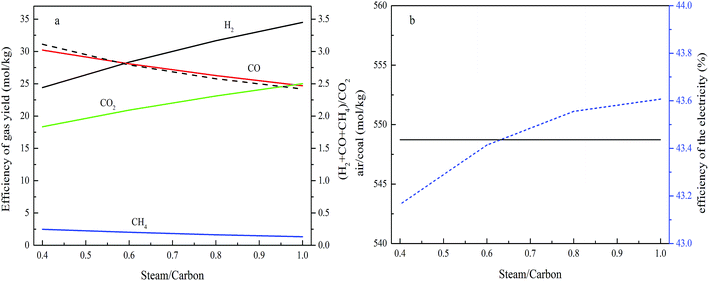
The effects of the steam/carbon ratio on the gas composition are measured when the air reactor temperature is 1000 °C, the fuel reactor temperature is 800 °C, the operating pressure is 2.0 MPa, the value of R is equal to 1.10, the carbon conversion in the fuel reactor is set at 0.9, and the steam/carbon ratio is varied from 0.4–1.0, and the results are shown in Fig. 8. The effects of the steam/carbon ratio on the efficiency of the gas yield are shown in Fig. 8a. This shows that with an increase in the steam/carbon ratio, the H2 and CO2 flow ratios increased, while CO and CH4 dropped continuously. The results show good agreement with other literature.25,26 The performance described above can be explained through the chemical equilibrium of reactions happening in the fuel reactor. The increase in steam means that a higher concentration of reactant in reactions (1), (3) and (6) will promote the gasification reactions in the forward direction. A higher steam/carbon ratio leads to more fuel gas (CO and H2) generation in the fuel reactor, and more energy in the coal being converted to a higher heat value in the fuel gas product.
 |
| | Fig. 8 The effect of the steam ratio on the process performance (a) the effect of pressure on gas yield, dashed line: (CO + H2 + CH4)/CO2, and (b) the effect of pressure on the air ratio and efficiency of electricity generation. | |
Fig. 8b shows that the air feed ratio remains constant as the steam/carbon ratio changes. The reason for this performance is the lack of change of the temperature, pressure and oxygen carrier feed ratio, and the efficiency shows a slight increasing trend with the steam/carbon ratio.
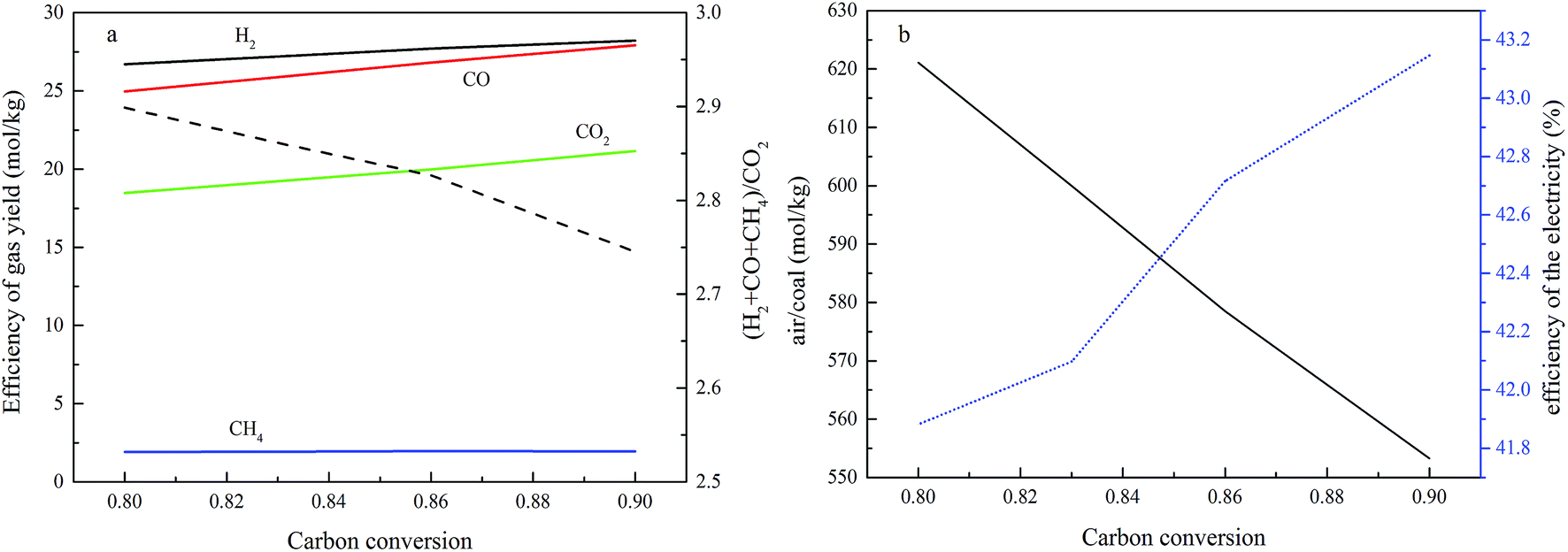
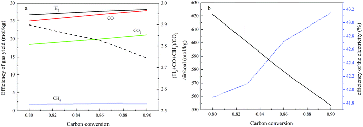
The effects of carbon conversion in the fuel reactor on the process performance
Due to the sudden drop in the gasification kinetics of the char, complete carbon conversion in the fuel reactor is not suggested during the optimal operation of a practical fuel reactor. As for the coal selected in this study, the threshold carbon conversion efficiency is 0.9, based on the gasification kinetics of char, so the gasification conversion of carbon is not suggested to be larger than 0.9, and the exact value of the conversion needs to be determined using other factors. In this study, the basic constant parameters in the simulation are a temperature of 1000 °C in the air reactor and 800 °C in the fuel reactor, an operating pressure of 2.0 MPa, a steam/carbon ratio of 0.6, and an oxygen carrier feed ratio of 1.10. The investigated range of the carbon conversion efficiency is between 0.8 and 0.9. The effects of carbon conversion in the fuel reactor on process performance are shown in Fig. 9. Fig. 9a shows that the total dry syngas productivity (the sum of H2, CO, CO2 and CH4) from the fuel reactor increased and the emission leakage of CO2 from the air reactor decreased when the threshold of carbon conversion efficiency was controlled to show an increase. In this case, less carbon residue is burned out inside the air reactor. Fig. 9b shows that the overall air supply decreased as the carbon conversion efficiency in the fuel reactor increased. Less carbon being converted in the fuel reactor led to more residual carbon being burnt in the air reactor and more being heat produced, thus, more air should be added to the air reactor to react with carbon and carry heat out from the air reactor to maintain the temperature. The efficiency of electricity generation increases upon increasing the carbon conversion in the fuel reactor, because less carbon residue being burned in the air reactor leads to more energy in the coal being converted to chemical energy in the syngas.
 |
| | Fig. 9 The effect of carbon conversion on the process performance (a) the effect of carbon conversion on gas yield, dashed line: (CO + H2 + CH4)/CO2, and (b) the effect of carbon conversion on the air ratio and efficiency of electricity generation. | |
Based on the aforementioned analysis, the parameters shown in Fig. 9 are converted to the parameters, x and y, which are based on carbon leakage from the air reactor, and the syngas yield refers to the total amount of H2 plus CO. As shown in Fig. 10, a decrease in the carbon conversion efficiency in the fuel reactor decreased both the syngas productivity and the electricity generation efficiency significantly within the range between 0.8 and 0.9, while the required air supply was only decreased slightly in the range between 0.8 and 0.9. An increase in the carbon conversion efficiency inside the fuel reactor is always suggested.
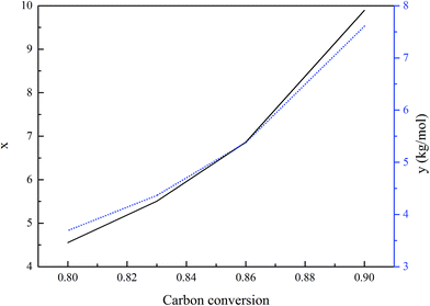 |
| | Fig. 10 The effect of carbon conversion on x and y. | |
5. Conclusions
A novel process for fuel syngas production from a chemical looping process, in which the carbon is not fully converted in the fuel reactor for fuel gas production and residual carbon is burnt in the air reactor using copper oxide as the oxygen carrier, is proposed. The results from the kinetics of char gasification suggest that the optimal threshold value for carbon conversion efficiency for the selected coal in this study is around 0.9, where further gasification of char residue is not suggested. A simulation of the processes, including chemical reactions and heat/mass balance, is carried out with software. The main objective is to study the effects of various conditions on the energy output parameters, such as energy efficiency and syngas quality, the carbon leakage from the air reactor, and the efficiency of electricity generation. The operating variables considered as part of the resource optimization analysis include: (i) the carbon conversion in the fuel reactor, (ii) the inlet temperature and pressure to the fuel reactor, and (iii) the steam-to-carbon ratio. The results suggest that higher carbon conversion in the fuel reactor is not good for the quality of the syngas, but favors the lower emission of CO2 and the efficiency of electricity generation. Meanwhile, the coal-direct chemical looping gasification process has the potential to convert coal to syngas and electricity, capturing 90% of CO2; the syngas can be adjusted to a reasonable value by varying temperature, pressure, and the oxygen carrier (OC) and steam feed ratio. The H2/CO ratio varied from 1.05 to 1.28, the CO2 concentration varied from 30.74% to 33.74%, the CH4 was between 4.10% and 5.21%, and the efficiency of the electricity was arranged between 26.6% and 45.5%.
Conflicts of interest
There are no conflicts to declare.
Acknowledgements
This study was supported by the Youth Science and Technology Talents Growth project of the Guizhou Provincial Education Department (Qianjiaohe KY Zi [2017]220), and the Energy Chemistry Laboratory in Guizhou Province (Qianjiaohe KY Zi [2017]009).
References
- I. Ahmed and A. Gupta, Pyrolysis and gasification of food waste: syngas characteristics and char gasification kinetics, Appl. Energy, 2010, 87, 101–108 CrossRef CAS.
- E. Cetin, B. Moghtaderi, R. Gupta and T. Wall, Biomass gasification kinetics: influences of pressure and char structure, Combust. Sci. Technol., 2005, 177, 765–791 CrossRef CAS.
- H. L. Chum and R. P. Overend, Biomass and renewable fuels, Fuel Process. Technol., 2001, 71, 187–195 CrossRef CAS.
- K. Mitsuoka, S. Hayashi, H. Amano, K. Kayahara, E. Sasaoaka and M. A. Uddin, Gasification of woody biomass char with CO2: The catalytic effects of K and Ca species on char gasification reactivity, Fuel Process. Technol., 2011, 92, 26–31 CrossRef CAS.
- J. A. Onwudili and P. T. Williams, Enhanced methane and hydrogen yields from catalytic supercritical water gasification of pine wood sawdust via pre-processing in subcritical water, RSC Adv., 2013, 3, 12432–12442 RSC.
- T. Mattisson, A. Lyngfelt and H. Leion, Chemical-looping with oxygen uncoupling for combustion of solid fuels, Int. J. Greenhouse Gas Control, 2009, 3, 11–19 CrossRef CAS.
- T. Mattisson, H. Leion and A. Lyngfelt, Chemical-looping with oxygen uncoupling using CuO/ZrO2 with petroleum coke, Fuel, 2009, 88, 683–690 CrossRef CAS.
- E. M. Eyring, G. Konya, J. S. Lighty and A. H. Sahir, Chemical Looping with Copper Oxide as Carrier and Coal as Fuel Boucle chimique pour la combustion du charbon avec un transporteur d'oxygène à base d'oxyde de cuivre, Oil Gas Sci. Technol., 2011, 66, 209–221 CrossRef CAS.
- R. A. Gaggioli, Second law analysis for process and energy engineering, in ACS symposium series, Oxford University Press, 1983, pp. 3–50 Search PubMed.
- C. Yan, W. Yang, J. T. Riley and W. P. Pan, A novel biomass air gasification process for producing tar-free higher heating value fuel gas, Fuel Process. Technol., 2006, 87, 343–353 CrossRef.
- Q. Song, R. Xiao, Z. Deng, L. Shen, J. Xiao and M. Zhang, Effect of Temperature on Reduction of CaSO4 Oxygen Carrier in Chemical-Looping Combustion of Simulated Coal Gas in a Fluidized Bed Reactor, Ind. Eng. Chem. Res., 2008, 47, 8148–8159 CrossRef CAS.
- W. Liu, M. Ismail, M. T. Dunstan, W. Hu, Z. Zhang, P. S. Fennell, S. A. Scott and J. S. Dennis, Inhibiting the interaction between FeO and Al2O3 during chemical looping production of hydrogen, RSC Adv., 2014, 5, 1759–1771 RSC.
- T. Andersen, H. M. Kvamsdal and O. Bolland, Gas turbine combined cycle with CO2 capture using auto-thermal reforming of natural gas, ASME Pap., 2000, 0162 Search PubMed.
- I. S. Ertesvåg, H. M. Kvamsdal and O. Bolland, Exergy analysis of a gas-turbine combined-cycle power plant with precombustion CO2 capture, Energy, 2005, 30, 5–39 CrossRef.
- S. Consonni and F. Viganò, Decarbonized hydrogen and electricity from natural gas, Int. J. Hydrogen Energy, 2005, 30, 701–718 CrossRef CAS.
- E. Eyring, G. Konya, J. Lighty, A. Sahir, A. Sarofim and K. Whitty, Chemical looping with copper oxide as carrier and coal as fuel, Oil Gas Sci. Technol., 2011, 66, 209–221 CrossRef CAS.
- F. Li, Z. Liang, L. G. Velazquez-Vargas, Y. Zachary and L. S. Fan, Syngas chemical looping gasification process: Bench-scale studies and reactor simulations, AIChE J., 2010, 56, 2186–2199 CrossRef CAS.
- S. G. Gopaul, A. Dutta and R. Clemmer, Chemical looping gasification for hydrogen production: A comparison of two unique processes simulated using ASPEN Plus, Int. J. Hydrogen Energy, 2014, 39, 5804–5817 CrossRef CAS.
- L. Zeng, F. He, F. Li and L.-S. Fan, Coal-Direct Chemical Looping Gasification for Hydrogen Production: Reactor Modeling and Process Simulation, Energy Fuels, 2012, 26, 3680–3690 CrossRef CAS.
- Z. Liang, H. Feng, F. Li and L. S. Fan, Coal-Direct Chemical Looping Gasification for Hydrogen Production: Reactor Modeling and Process Simulation, Energy Fuels, 2012, 26, 3680–3690 CrossRef.
- R. Porrazzo, G. White and R. Ocone, Aspen Plus simulations of fluidised beds for chemical looping combustion, Fuel, 2014, 136, 46–56 CrossRef CAS.
- S. Ilaiah, D. V. Sasikanth and B. Satyavathi, Process simulation of a entrained fluidized bed biomass gasification using aspen plus, 3rd International Conference on Recent Trends in Engineering Science and Management (ICRTESM-16), Vedant College of Engineering and Technology, Bundi, Rajasthan, 10th April 2016, ISBN: 978-81-932074-4-4 Search PubMed.
- L. Liu, Y. Cao and Q. Liu, Kinetics studies and structure characteristics of coal char under pressurized CO2 gasification conditions, Fuel, 2015, 146, 103–110 CrossRef CAS.
- L. Liu, Y. Cao, Q. Liu and J. Yang, Experimental and kinetic studies of coal–CO2 gasification in isothermal and pressurized conditions, RSC Adv., 2017, 7, 2193–2201 RSC.
- L. Shen, Y. Gao and J. Xiao, Simulation of hydrogen production from biomass gasification in interconnected fluidized beds, Biomass Bioenergy, 2008, 32, 120–127 CrossRef CAS.
- S. Rapagna, N. Jand, A. Kiennemann and P. Foscolo, Steam-gasification of biomass in a fluidised-bed of olivine particles, Biomass Bioenergy, 2000, 19, 187–197 CrossRef CAS.
|
| This journal is © The Royal Society of Chemistry 2017 |
Click here to see how this site uses Cookies. View our privacy policy here. 
 Open Access Article
 This Open Access Article is licensed under a
  *a,
Yan Cao*b,
Dongran Mac,
Qingcai Liuc and
Jian Yangc
*a,
Yan Cao*b,
Dongran Mac,
Qingcai Liuc and
Jian Yangc