 Open Access Article
Investigation of the crystallization behaviors in a sub-micron space using carbon nanocones†
Lele Xuab,
Yifei Gebc,
Jianbo Liangc,
Jianxun Xu *b and
Xing Lu
 *a
*a
aState Key Laboratory of Materials Processing and Die & Mould Technology, School of Material Science and Engineering, Huazhong University of Science and Technology (HUST), Wuhan, 430074, China. E-mail: lux@hust.edu.cn
bChinese Academy of Science Key Laboratory for Biomedical Effects of Nanomaterials and Nanosafety, National Center for Nanoscience and Technology of China, No. 11, Bei yi tiao, Zhong guan cun, Beijing, 100190, China. E-mail: xujx@nanoctr.cn
cDepartment of Chemistry, Capital Normal University, No. 105, North Road, West 3rd Ring Road, Beijing, 100048, China
First published on 31st October 2017
Abstract
Up to now, there have been many research studies that have revealed the unique phenomena of various materials encapsulated in a confined nano-sized space, such as in the interior of carbon nanotubes (CNTs). Confined in such a space several nanometers in size, these materials showed many different and interesting properties. However, the morphology and behaviors of these materials encapsulated in a comparatively bigger space, i.e., from tens of nanometers to microns, have been little investigated. In this work, carbon nanocones (CNCs), which are multilayered graphene-like nanomaterials with a hollow conical structure and an inner size varying continuously from several nanometers to micrometers, were used as the workhorse to investigate the nano-confinement effects on different scales. Gd acetate was adopted to be incorporated into the conical inner space of the CNCs. The corresponding Gd oxide, formed upon heating, showed a unique morphology and crystallization behavior in this sub-micron space. The confined Gd oxide was conical in shape, perfectly fitting the interior of the CNCs. Several crystallization orientations were often presented in the Gd oxide cone structure, and single crystallization was also observed located close to the apex of the CNCs. The crystal size of Gd oxide was over 100 nm, implying the effective scale of the confinement phenomenon between the CNCs and Gd oxide. Moreover, we further found that the Gd oxide cone retained its structure, instead of forming a spherical particle when it moved outward from the CNC driven by a high temperature, indicating the high stability of the conical Gd oxide nanocrystals.
1 Introduction
Carbon materials, such as carbon nanotubes (CNTs),1 single-walled carbon nanohorns (SWCNHs)2 and graphene,3 are widely used in various fields due to their remarkable physical and chemical properties. CNTs and SWCNHs can be seen as rolls of single-sheet graphene that have a tubular structure. Taking advantage of the hollow inner spaces in these tubular structures, various kinds of materials have been reported to be incorporated inside CNTs and SWCNHs, such as H2,4,5 C60,6 Gd compounds7 and cisplatin (an anti-cancer drug).8 Therefore, CNTs and SWCNHs are potentially useful for various purposes, such as gas storage, catalyst support and drug carriers. Up to now, researchers have conducted many studies on encapsulation using CNTs and SWCNHs and reported the unique behaviors of the conjugate materials. For example, a recent study by Prof. Goodson and his colleagues proved that the thermal properties of CNTs can be remarkably modulated by encapsulation of fullerenes inside.9 On the other hand, Dr Kazu Suenaga et al. demonstrated that the electronic structure of single-walled CNTs can also be tuned through controlling the encapsulated C70 molecular orientations.10 Moreover, AgBr was proved to have a high stability to light irradiation after being encapsulated inside CNTs.11 Professor Xinhe Bao et al. designed a catalyst with iron nanoparticles confined inside pea-pod-like carbon nanotubes exhibiting a high activity and remarkable stability as a cathode catalyst.12 However, most of the incorporation studies and discussion on the nano-confinement phenomena have been performed on a scale of several nanometers, due to the small inner diameter of CNTs.13 Until now, there have been few research studies investigating the structure and behaviors of encapsulated materials on a larger scale up to micrometers. The effective scale of the nano-confinement phenomena remains unclear. Aiming to answer the above questions, we adopted carbon nanocones (CNCs) in this work, which are multilayered graphene-like carbon nanomaterials with a conical structure and an inner size continuously varying from several nanometers to micrometers. CNCs are regarded as a promising workhorse to study the filling phenomena and the crystallization behaviors of foreign materials on a nano-micron scale.CNCs are seamless and hollow graphene cones with five distinct apex angles, namely 19.2°, 38.9°, 60°, 84.6° and 112.9°, and were produced by pyrolysis of heavy oil in a carbon electric arc.14,15 Due to their unique conical shape and high mechanical stability, CNCs can be used as a kind of novel atomic force microscopy tip. Abraham G. et al. have successfully encapsulated gold tips in CNCs via nanomanipulation to enhance the mechanical stability of the gold nanotips, which exhibit high plasticity limiting their application in some nanodevices.16 Different from CNTs and SWCNHs, CNCs have a closed apex and the other side is open, which is suitable for incorporation experiments. The graphene-like structure of CNCs also provides a stable support for observing the encapsulated foreign materials using electron microscopy. Consequently, we successfully obtained Gd oxide nano-crystals that perfectly fit in the inner spaces of CNCs. The diameter of the conical Gd oxide crystals ranges from several nanometers to hundreds of nanometers. In addition, the conical Gd oxide crystals showed a high stability even at a temperature high enough to drive them apart from the apex of the CNCs.
2 Experimental section
The pristine CNCs were purchased from n-Tec AS. The CNC sample that was annealed at 2700 °C to improve the crystallinity of the material is denoted as CNCs-1 in this paper. Gd acetate was purchased from J&K Scientific company. Gd acetate (5 mg) and CNCs-1 (5 mg) were dispersed and stirred in ethanol (5 ml) at room temperature for 18 h. The mixture was filtered with filter paper (the pore-size is 1 μm) and washed with ethanol (20 ml, 1 ml per time) 20 times to remove the excess Gd acetate outside CNCs-1 and some impurities to get GdAc@CNCs-1. After that, the sample was dried at 80 °C for 20 h in air, and then heated in a horizontal-chamber furnace at 700 °C under vacuum. In addition, we also used a CNC sample which was not annealed at 2700 °C (which is denoted as CNCs-2 in this paper) to incorporate Gd acetate as a comparison.The morphology and structure of the samples were studied by a transmission electron microscope (TEM) (Tecnai G2 F20U-TWIN) and scanning transmission electron microscope (STEM), equipped for energy dispersive X-ray spectroscopy (EDX) and selected area electron diffraction (SAED). The TEM and STEM were operated at 200 kV. For the microscopic observations, the samples were firstly dispersed in ethanol by ultrasonication, and then dropped onto a porous carbon film-coated Cu grid.
3 Results and discussion
3.1. Morphology and structure of encapsulated Gd compounds
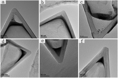
Compared to CNCs-1, which were annealed at a high temperature, CNCs-2 usually have many impurities (most of them are carbonaceous fragments) in the inner space close to the apex and the degree of graphitization is not as high as for CNCs-1. Meanwhile, CNCs-1 are very clean containing few impurities as shown in Fig. S1.† And the graphene layers in CNCs-1 are straight and neat. Fig. 1 shows six TEM images of CNCs-1 and CNCs-2 with Gd compounds incorporated inside before and after heat treatment. Fig. 1a, b, and 1d, e are GdAc@CNCs-2 and GdAc@CNCs-1 before heat treatment, respectively, and Fig. 1c and f are Gd oxide encapsulated inside CNCs-2 and CNCs-1, respectively, after heat treatment at 700 °C. The apex of the pristine CNCs was vacant inside (as presented in Fig. S1†), while a black area of Gd acetate clusters was found at the apex of the CNCs, as shown in Fig. 1. It is noteworthy that the incorporated Gd acetate clusters in CNCs-1 and CNCs-2 appeared in different structures. As seen in Fig. 1a and b, Gd acetate encapsulated inside CNCs-2 forms somewhere not far from the apex of CNCs-2, leaving the apex vacant. And a thin film of Gd acetate was formed adherent to the side wall of the CNCs-2 on a large scale. In contrast, Gd acetate clusters encapsulated inside the apex of CNCs-1 exist in a cone structure consistent with the inner shape of the CNCs-1 (Fig. 1d and e). This is the first time that conical nanomaterials formed by self-aggregation have been obtained in confined spaces. Their morphology is different from that of Gd compounds encapsulated inside CNTs in previous reports. Similarly, the Gd compounds formed inside SWCNHs were also spherical nanoparticles of a few nanometers, even though SWCNHs comprise conical nanohorns.17 Furthermore, the diameters of the encapsulated materials inside the CNTs and SWCNHs were only a few nanometers according to previous research studies,13 but the filling diameter of the Gd compounds inside the CNCs was up to hundreds of nanometers. The maximum filling diameter observed in our experiments was 428 nm, and most of them fall in the range of 100–200 nm (the images are shown in Fig. S2†).It is interesting to observe two different morphologies in the encapsulated Gd compounds inside the CNCs, and we can explain the different incorporation behaviors of the two kinds of CNCs by taking into account their structural features. As reported, the as-produced CNC sample consists of a mixture of carbon nanocones (∼20%), carbon nanodiscs (∼70%) and amorphous carbons, as well as some impurities (∼10%) without post heat-treatment.18 The impurities may stop Gd acetate from entering the apex of CNCs-2, resulting in the morphology shown in Fig. 1a and b. In contrast, CNCs-1 treated at a high temperature have less obstacles to the incorporation of Gd acetate, and therefore we can observe cone-shaped Gd acetate incorporated in CNCs-1. On the other hand, the different chemical structures on the surfaces of CNCs-1 and CNCs-2 are an important reason resulting in their different encapsulation behaviors. Compared with CNCs-1, CNCs-2 are highly graphitized and contain few chemical groups on the surface. The different chemical environment in the interior of the CNCs affords different affinities between the encapsulated Gd compounds and the CNCs. It can be concluded that the chemical groups (mainly oxygen-containing functional groups) prevent Gd compounds from entering the apex of CNCs-2. This repelling effect is more apparent in a smaller space close to the apex of the CNCs-2. In contrast, the highly graphitized inner surface of CNCs-1 seems to have a high affinity to Gd compounds, resulting in a perfect conical shape of the encapsulated compounds fitting the inner space of the CNCs-1.
Furthermore, it is known that Gd acetate is transformed into Gd oxide by heat treatment above 650 °C.19 For CNCs-2, it is clear to see that the Gd acetate clusters change into Gd oxide nanoparticles after heat treatment at 700 °C and some ultrafine Gd oxide nanoparticles successfully move to the apex of CNCs-2, although most of them still stay where they aggregated before (Fig. 1c). However, the Gd oxide retains the same cone-shaped structure and location as the Gd acetate clusters encapsulated in CNCs-1, as shown in Fig. 1f.
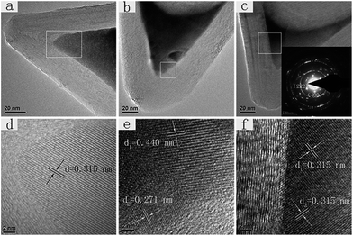
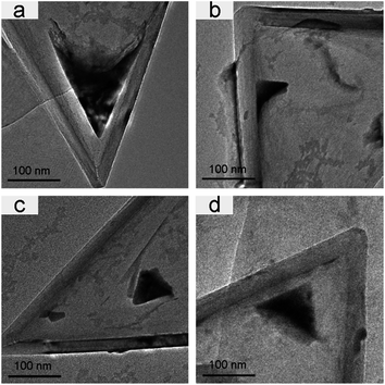
Fig. 2 presents high-resolution TEM (HRTEM) images of Gd oxide embedded inside CNCs-1 after heat treatment. Both single-crystal and polycrystal structural domains were observed. Fig. 2a and d are a TEM image and HRTEM image of a Gd oxide single-crystal, and Fig. 2b, c, and 2e, f are TEM images and HRTEM images of Gd oxide polycrystals. According to previous reports, the filling material usually has a small crystal domain size of less than 10 nm limited by the diameter of CNTs.20,21 However, the size of the gadolinium oxide single-crystals growing inside CNCs-1 in our study can reach more than 50 nm laterally with an axial length of up to 72 nm (Fig. 2a and S3†). And the sizes of the gadolinium oxide polycrystals are in the range from 50 nm to 400 nm, among which the maximum size is up to 428 nm (as seen in Fig. S2†). The average values were 100–200 nm. The inter-lattice distance of the single-crystal Gd oxide in Fig. 2d was estimated to be 0.315 nm. Meanwhile, three inter-lattice distances, i.e., 0.315 nm, 0.271 nm and 0.440 nm, were found in the polycrystal Gd oxides in Fig. 2e and f, which can be assigned to the layer spacing of cubic Gd2O3 (222), (400), and (211), respectively (d(222) = 0.312 nm, d(400) = 0.270 nm, d(211) = 0.441 nm). We also performed selected area electron diffraction (SAED) for an individual Gd2O3@CNC-1, as shown in the inset of Fig. 2c. As a result, the spots indexed as (222) and (400) diffractions from cubic Gd2O3 were identified. According to the statistical results in our observations, most of the Gd oxide crystals encapsulated in CNCs-1 were polycrystals and only around 5% of Gd oxide@CNCs-1 were single-crystals. This is similar to previous studies in which both polycrystals and single-crystals usually co-exist in the composites of metals and CNTs, e.g. Au@CNTs, and Pt@CNTs.22 On the other hand, monocrystalline FeCo nanowires encapsulated inside CNTs were reported to be successfully produced by aerosol thermolysis.23 However, the mechanism to control the preferential crystal structures of foreign materials in a confined space remains unclear.24 Although single-crystals of encapsulated materials can be often observed on the scale of several nanometers, the growth direction and thus crystal morphology seemed to be easily disturbed during growth on a larger scale, resulting in polycrystals, as shown in our results.
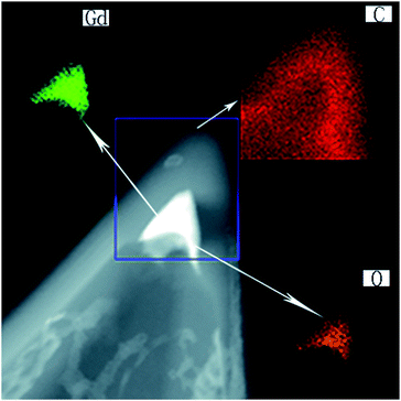
Moreover, we performed elemental mapping of Gd2O3@CNCs-1 under STEM, as shown in Fig. 3. It is clear to see that the material encapsulated inside the inner spaces was made of gadolinium (the green area) and oxygen (the yellow area) while the apex of the CNC was made of carbon (the red area). These results confirmed that the black material inside the apex of the CNC-1 was Gd acetate clusters and transformed into Gd2O3 crystals when heated at 700 °C.
Consequently, we obtained Gd compounds encapsulated in CNCs showing various morphologies and structures. When using CNCs-1 as the filling template, we can get cone-shaped Gd2O3 crystals in a large size range up to hundreds of nanometers, which was not reported previously. This result indicates that the effective nano-confinement size can be around several hundreds of nanometers. The confined Gd2O3 crystals were mostly polycrystals; meanwhile, large single-crystal domains located at the apex of the CNCs were also observed. The size of the Gd oxide single-crystals in our study can reach more than 50 nm laterally with an axial length of up to 72 nm. Our work demonstrates that CNCs can be used as a unique workhorse to study the crystallization behaviors of foreign materials in a confined space continuously from nanometers to micrometers.
3.2. The filling percentage of CNCs with different apex angles
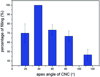
To estimate the percentage of encapsulation, we randomly observed 110 CNCs-1 from the heat-treated sample under TEM. The statistical result is that 70 CNCs-1 contained Gd2O3 nano-crystals, giving a filling percentage of 64%. Since CNCs have five different apex angles (19.2°, 38.9°, 60°, 84.6°, 112.9°), the encapsulation yield is different for CNCs-1 with different apex angles. In order to determine the relationship between the apex angle of CNCs-1 and the filling ratio, we selected 10 CNCs-1 of each apex angle and calculated the filling ratio of the CNCs-1 with different apex angles. Three Gd2O3@CNC-1 samples were used for such calculations. As shown in Fig. 4, the filling ratio of CNCs with the apex angle of 38.9° is the highest. Meanwhile, the CNCs with the apex angle of 112.9° are difficult to fill. Generally, a CNC with a small apex angle is easier to fill than a large-angled CNC.3.3. The dynamics of cones encapsulating Gd2O3 under prolonged heating
It has been proved above that the encapsulated Gd acetate decomposed into conical Gd2O3 crystals when heated at 700 °C. But the structure and behaviors of the Gd2O3 nanocones during a prolonged heat treatment were not clear. In our experiments after heating the samples at 700 °C for 2 h, some interesting phenomena were observed.As shown in Fig. 5, the Gd2O3 crystal started to separate from the apex of the CNC and had a tendency to move out of the CNC-1 after heat treatment at 700 °C for 2 h. The interesting thing was that the shape of the Gd2O3 crystal remained unchanged and was consistent with the apex of CNC-1. Thus, we obtained a cone-shaped Gd2O3 crystal and a vacant CNC-1. Referring to previous reports, Gd2O3 crystals encapsulated in the sheath of SWCNHs would move from the sheath to the center of the SWCNHs and aggregate forming a large spherical clumped crystal when heated at a high temperature.17 However in our study, the cone-shaped Gd2O3 crystal kept the same structure, even though it was driven to move outward from the CNC-1 during heating, indicating the high stability of the Gd2O3 cones. The morphology evolution and structural stability of the Gd2O3 cones inside CNCs under heating were also investigated in our in situ TEM observations, shown in Fig. S4.† In conclusion, from these preliminary results, it is possible to obtain cone-shaped target nanomaterials by taking advantage of this encapsulation-and-release feature of CNCs.
4 Conclusions
In summary, we investigated the encapsulation and the crystallization behaviors of Gd compounds in a confined nanospace using CNCs on a scale from nanometers to micrometers for the first time. Our results showed that the average crystal size of Gd oxide was over 100 nm, and the maximum can be up to 428 nm, which is much larger than the previously reported values. These results reveal that the nano-confinement effect can still function at a scale of hundreds of nanometers. Both single-crystal and polycrystal Gd2O3 structures can form in the confined space. And the size of the single-crystals of Gd oxide can reach more than 50 nm laterally with an axial length of up to 72 nm. Moreover, the thus-formed Gd oxide nanocones kept the same cone structure after being heated at a high temperature, implying high stability. The novel Gd oxide nanocones, as well as the filled CNCs, may find some new applications due to their new structures, such as in functional SPM probes, nano-catalysis etc. Our work also demonstrates that CNCs can be used as a unique workhorse to study the structure and behaviors of foreign materials in a confined space continuously from nanometers to micrometers.Conflicts of interest
There are no conflicts to declare.Acknowledgements
This work was financially supported by the Ministry of Science and Technology of China (2016YFA0203200), the National Thousand Talent Program of China, and the National Science Foundation of China (51472095, 51672093, 51602112, and 51602097).Notes and references
- S. lijima, Nature, 1991, 354, 56–58 CrossRef.
- S. Iijima, M. Yudasaka, R. Yamada, S. Bandow, K. Suenaga, F. Kokai and K. Takanashi, Chem. Phys. Lett., 1999, 309, 165–170 CrossRef CAS.
- A. K. Geim, K. S. Novoselov, S. V. Morozov, D. Jiang, Y. Zhang, S. V. Dubonos, I. V. Grigorieva and A. A. Firsov, Science, 2004, 306, 666–669 CrossRef PubMed.
- A. C. Dillon, K. M. Jones, T. A. Bekkedahl and C. H. Kiang, et al., Nature, 1997, 386, 377–379 CrossRef CAS.
- W. Xu, K. Takahashi, Y. Matsuo, Y. Hattori, M. Kumagai, S. Ishiyama, K. Kaneko and S. Iijima, Int. J. Hydrogen Energy, 2007, 32, 2504–2512 CrossRef CAS.
- R. Yuge, M. Yudasaka, J. Miyawaki, Y. Kubo, T. Ichihashi, H. Imai, E. Nakamura, H. Isobe, H. Yorimitsu and S. Iijima, J. Phys. Chem. B, 2005, 109, 17861–17867 CrossRef CAS PubMed.
- A. Hashimoto, et al., Proc. Natl. Acad. Sci. U. S. A., 2004, 101, 8527–8530 CrossRef CAS PubMed.
- K. Ajima, M. Yudasaka, T. Murakami, A. Maigne, K. Shiba and S. Iijima, Mol. Pharm., 2005, 2, 475–480 CrossRef CAS PubMed.
- T. Kodama, M. Ohnishi, W. Park, T. Shiga, J. Park, T. Shimada, H. Shinohara, J. Shiomi and K. E. Goodson, Nat. Mater., 2017, 16, 892–897 CrossRef CAS PubMed.
- S. Okubo, T. Okazaki, K. Hirose-Takai, K. Suenaga, S. Okada, S. Bandow and S. Iijima, J. Am. Chem. Soc., 2010, 132, 15252–15258 CrossRef CAS PubMed.
- K. Kobayashi, K. Suenaga, T. Saito, H. Shinohara and S. Iijima, Adv. Mater., 2010, 22, 3156–3160 CrossRef CAS PubMed.
- D. Deng, L. Yu, X. Chen, G. Wang, L. Jin, X. Pan, J. Deng, G. Sun and X. Bao, Angew. Chem., 2013, 52, 371–375 CrossRef CAS PubMed.
- J. Miyawaki, M. Yudasaka, H. Imai, H. Yorimitsu, H. Isobe, E. Nakamura and S. Iijima, J. Phys. Chem. B, 2006, 110, 5179–5181 CrossRef CAS PubMed.
- M. Ge and K. Sattler, Chem. Phys. Lett., 1994, 220, 192–196 CrossRef CAS.
- A. Krishna, M. M. J. Treacy and J. Hugdahl, et al., Nature, 1997, 388, 451–454 CrossRef.
- A. G. Cano-Marquez, et al., Sci. Rep., 2015, 5, 10408 CrossRef CAS PubMed.
- R. Yuge, T. Ichihashi, J. Miyawaki, T. Yoshitake, S. Iijima and M. Yudasaka, J. Phys. Chem. C, 2009, 113, 2741–2744 CAS.
- S. N. Naess, A. Elgsaeter, G. Helgesen and K. D. Knudsen, Sci. Technol. Adv. Mater., 2009, 10, 065002 CrossRef PubMed.
- G. A. M. Hussein, J. Phys. Chem., 1994, 98, 9657–9664 CrossRef CAS.
- D. Zhou, S. Seraphin, J. Jiao, J. C. Withers and R. Loutfy, Appl. Phys. Lett., 1993, 63, 2073–2075 CrossRef.
- Y. Lu, Z. Zhu and Z. Liu, Carbon, 2005, 43, 369–374 CrossRef CAS.
- A. Govindaraj, B. C. Satishkumar, M. Nath and C. N. R. Rao, Chem. Mater., 2000, 12, 202–205 CrossRef CAS.
- A. L. Elías and J. A. Rodríguez-Manzo, et al., Nano Lett., 2005, 5, 467–472 CrossRef PubMed.
- F. Banhart, N. Grobert, M. Terrones, J. C. Charlier and P. M. Ajayan, Int. J. Mod. Phys. B, 2001, 15, 4037–4069 CrossRef CAS.
Footnote |
| † Electronic supplementary information (ESI) available. See DOI: 10.1039/c7ra10718h |
| This journal is © The Royal Society of Chemistry 2017 |

