
 Open Access Article
 This Open Access Article is licensed under a
 Creative Commons Attribution 3.0 Unported Licence
Synthesis and photoluminescence of Mn4+ activated ternary-alkaline fluoride K2NaGaF6 red phosphor for warm-white LED application†
Shijie Qiu,
Hengwei Wei,
Mengmeng Wang,
Shuai Zhang,
Yang Zhou,
Ling Xu ,
Xiaoming Wang* and
Huan Jiao*
,
Xiaoming Wang* and
Huan Jiao*
Key Laboratory of Macromolecular Science of Shaanxi Province, School of Chemistry & Chemical Engineering, Shaanxi Normal University, Xi'an 710062, Shaanxi Province, P. R. China. E-mail: xmwang@snnu.edu.cn; jiaohuan@snnu.edu.cn
First published on 30th October 2017
Abstract
A novel ternary-alkaline red emitting fluoride phosphor K2NaGaF6:Mn4+ was successfully synthesized through co-precipitation method. The crystal structure, morphology, electronic band structure and luminescence properties of K2NaGaF6:Mn4+ phosphors were investigated in details by using Rietveld refinement of X-ray diffraction data, scanning electron microscopy (SEM), density functional theory (DFT) calculation and different reaction parameters. The K2NaGaF6 host has a cubic unit cell with the space group Fm![[3 with combining macron]](https://www.rsc.org/images/entities/char_0033_0304.gif) m and lattice parameters of a = 8.2577 (4) Å, Z = 4, Vcell = 563.08 (8) Å3. Under blue light excitation, Mn4+ activated K2NaGaF6 exhibits a bright narrow-band red emission. The PL properties of the K2NaGaF6:Mn4+ red phosphors were optimized with different Mn4+ concentrations and aging times. A warm-white LED device was fabricated using a blue LED chip combined with commercial yellow YAG:Ce3+ phosphor and synthesized K2NaGaF6:Mn4+ red phosphor. The color rendering index (CRI, Ra = 81.6) and corresponding color temperature (CCT = 3643 K) easily reached the commercial warm white light LED standards (Ra > 80 and CCT < 4000 K). All these results indicate that K2NaGaF6:Mn4+ phosphor would be a suitable red phosphor candidate for warm-white LED applications.
m and lattice parameters of a = 8.2577 (4) Å, Z = 4, Vcell = 563.08 (8) Å3. Under blue light excitation, Mn4+ activated K2NaGaF6 exhibits a bright narrow-band red emission. The PL properties of the K2NaGaF6:Mn4+ red phosphors were optimized with different Mn4+ concentrations and aging times. A warm-white LED device was fabricated using a blue LED chip combined with commercial yellow YAG:Ce3+ phosphor and synthesized K2NaGaF6:Mn4+ red phosphor. The color rendering index (CRI, Ra = 81.6) and corresponding color temperature (CCT = 3643 K) easily reached the commercial warm white light LED standards (Ra > 80 and CCT < 4000 K). All these results indicate that K2NaGaF6:Mn4+ phosphor would be a suitable red phosphor candidate for warm-white LED applications.
1. Introduction
White light-emitting diodes (W-LEDs) received extensive attention in recent years, because of their outstanding advantages such as high efficiency, energy-saving, long-term reliability and environment friendliness.1,2 Currently, the mainstream products of W-LEDs in the market are mainly packaged with blue InGaN chips and yellow phosphor Y3Al5O12:Ce3+ (YAG). However, due to the lack of red-emitting components, the related W-LEDs present a high correlated colour temperature (CCT > 4000 K) and a low colour rendering index (CRI, Ra < 80),3–5 which result a cold white light emission. Therefore, exploring suitable red phosphors for W-LEDs is an important strategy to improve the luminescence quality of W-LEDs.Recently, Mn4+ doped fluoride phosphors have been widely investigated due to their simple synthesis strategy and excellent luminescence properties.4,6,7 They have a strong broad absorption in the near UV and blue region which match well with the UV and blue LED chips and emit a series of narrow red emissions from 600 nm to 650 nm. Compared to other W-LEDs red phosphors, Mn4+ doped fluoride shows better chemical stability than sulfide phosphors, and simpler synthesis conditions and lower cost than nitride phosphors. Many series of fluoride phosphors such as A2MF6:Mn4+ (A = Na, K, Rb, Cs, M = Si, Ge, Sn, Zr, Ti),8–15 BMF6:Mn4+ (B = Mg, Ca, Ba, Zn, M = Si, Ge, Ti)16,17 and A3MF6:Mn4+ (A = Na, K, M = Al, Ga)18–22 have been reported. All of these Mn4+ activated fluorides phosphors exhibit intense broadband excitation and sharp red emission, which can be efficiently excited by near-UV or blue light and emit red light urgently required in warm W-LEDs.
Tuning phosphors emission bands is an important approach to improve the luminescence performance of W-LEDs. A usual way is to replace neighbour cations, changing the activator ions structure environment and making the luminescence properties change continuously. This strategy has been applied in many fluorides systems, for example, cubic elpasolite phosphors A2BLF6:Mn4+ (A: larger alkali ion (K), B: smaller alkali ion (Na, Li), L: trivalent cation (Al, Sc, Ga)),23–28 Mn4+ ions occupy the positions of Al3+, Sc3+, or Ga3+. Recently, Wang group reported two novel Mn4+-doped fluoride phosphors K2LiAlF6:Mn4+ and K2NaAlF6:Mn4+.24,29 These substitutions are mainly focused on the A site and B site. In order to improve the luminescent properties of fluoride phosphors, for example luminous intensity, thermal quenching effect, quantum efficiency and so on, more attempts could be tried on L site or the 3 cations combinations. With diverse cation radius, different structure and luminescent properties can be expected.
In this paper, we successfully synthesized a series of ternary-alkaline gallate fluoride red K2NaGaF6:Mn4+ phosphors through co-precipitation method at room-temperature. This phosphor shows pale yellow in daylight and emits a narrow-band red light under blue light excitation. The crystal structure, morphology, composition, electronic band structure and luminescence properties were investigated in details. In addition, the reaction parameters such as Mn4+ doping concentration and aging time have been investigated to optimize the photoluminescence properties. Finally, we fabricated a warm W-LED using a blue LED chip combined with a yellow YAG:Ce3+ phosphor and a K2NaGaF6:Mn4+ red phosphor, and the luminescence properties of this warm W-LED was obtained.
2. Experimental
2.1 Raw materials
The ternary-alkaline phosphors were synthesized from the raw chemicals KF (99.5%), NaF (99.99%), Ga2O3 (99.99%), acetone (A.R.) and HF (49%). Main chemicals were purchased from Aladdin Chemistry, China. All of these starting reagents were used directly without any further purification.2.2 Synthesis method
Compounds of K2NaGaF6:Mn4+ were prepared through a co-precipitation method according to ref. 31. In a typical procedure of preparing K2NaGaF6:Mn4+ (see Fig. 1), 0.4686 g of Ga2O3 and different amount of K2MnF6 were dissolved in 15 mL HF solution under stirring. Then, 0.9682 g KF and 0.3449 g NaF were added into the solution. The mixed solution was stirred for 30 min. After putting the plastic beaker into ice-water bath for several hours, washed with acetone and dried at 70 °C for 2 h. The pale yellow powder of K2NaGaF6:Mn4+ red phosphors were obtained.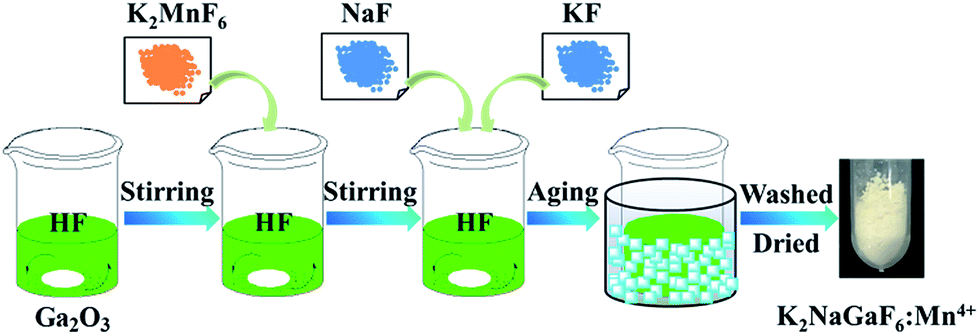 | ||
| Fig. 1 Synthesis diagram of K2NaGaF6:Mn4+ phosphors through co-precipitation method. | ||
For optimization of the luminescence performance, different concentrations of Mn4+ doped K2NaGaF6 samples were synthesized using different mole ratios of Ga to Mn and the real doped concentrations has been measured, as shown in Table 1.
| Samples | Moar ratio of Ga to Mn | Dopant amount of Mn (mol%) in K2NaGaF6 |
|---|---|---|
| S1 | 100![[thin space (1/6-em)]](https://www.rsc.org/images/entities/char_2009.gif) :1.0 :1.0 |
0.82 |
| S2 | 100:1.5 |
1.33 |
| S3 | 100:1.8 |
1.62 |
| S4 | 100:2.0 |
1.76 |
| S5 | 100:2.5 |
2.12 |
| S6 | 100:3.0 |
2.67 |
| S7 | 100:3.5 |
3.30 |
2.3 Characterization
The crystal structures of the synthesized powders were analysed by a Rigaku MiniFlex 600 X-ray powder diffractometer. Powder's XRD data were collected in continuous scanning mode in a 2θ range of 10–80°, with a step size of 0.02°, a tube voltage of 40 kV, and a tube current of 15 mA. Rietveld refinements on X-ray diffraction data were performed using the software TOPAS 4.2.Density functional theory (DFT) calculation for K2NaGaF6 was performed with the Cambridge Serial Total Energy Package (CASTEP) code, in which a plane wave basis set was chosen for expansion of valence-electron wave functions at the local density approximation (LDA) level.30 There were two steps of calculations to get the band structure of K2NaGaF6. The first step was to optimize its crystal structure using the Broyden–Fletcher–Goldfarb–Shannon (BFGS) method. The second step was to calculate the band structure and density of states (DOS). In this calculation, the energy cutoff was set as 450 eV. Criterion for the self-consistent field (SCF) was eigenenergy convergence within 1.0 × 10⁻⁷ eV per atom.
The morphology and EDX mapping of samples was investigated by scanning electron microscopy (SEM, Philips-FEI Quanta 200, America) with an attached energy-dispersive X-ray spectrometer (EDS, INCA-Oxford, High Wycombe, UK).
The Mn4+ content in samples was measured on a flame atomic absorption spectrophotometer (FAAS) TAS-990F (Beijing Purkinje General Instrument Co., Ltd., China). PL spectra were acquired with a Hitachi F-4600 fluorescence spectrophotometer with the excitation and emission slits set to 2.5 nm, and the xenon lamp was used as excitation source. The diffuse reflectance ultraviolet-visible spectra (DRS) were collected on a UV-vis-NIR spectrophotometer UV-lambda 950 (PerkinElmer General Instrument Co., Ltd., America). The luminescence quantum efficiencies of obtained samples were measured using a quantum efficiencies measurement system C9920-02G (Hamamatsu, Japan).
2.4 Fabrication of W-LEDs
For the purpose of exploring reliability under LED operating conditions, prototype W-LEDs were fabricated with commercial yellow phosphor YAG:Ce3+, the synthesized red phosphor K2NaGaF6:Mn4+ in this work, and blue InGaN chips. Luminescence properties of the obtained devices were measured at various drive current changed from 25 mA to 350 mA.3. Results and discussion
3.1 Structure and spectroscopic analysis
Fig. 2 shows the crystal structure of K2NaGaF6 and XRD patterns of doped and non-doped K2NaGaF6. In Fig. 2(a), Ga3+ and Na+ ions are surrounded by six F− ions to form [GaF6] and [NaF6] octahedrons ionic groups, respectively. K+ ion locates at the centre of four octahedrons forming a [KF12] decahedral cage. The [GaF6] and [NaF6] octahedrons are linked through vertex-share F− ions. The effective radius of Ga3+ ion and Mn4+ ion at a CN = 6 (CN = coordination number) are 0.62 Å and 0.53 Å, respectively.20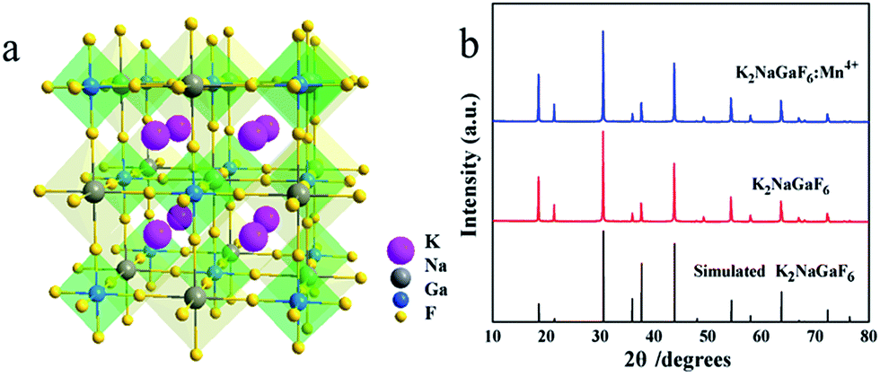 | ||
| Fig. 2 (a) Structure diagram and (b) XRD patterns of K2NaGaF6 and K2NaGaF6:Mn4+ (1.76 mol% Mn4+). | ||
Fig. 2(b) shows XRD patterns of K2NaGaF6, K2NaGaF6:Mn4+ as well as the simulated card of K2NaGaF6. With 1.76 mol% Mn4+ doping in K2NaGaF6, no impurity peaks were observed, which indicated the doped phosphor has a pure phase as the non-doped samples. Using K2NaAlF6 as a structure model, the Rietveld refinements based on powder XRD data indicated that the prepared K2NaGaF6 has the cubic unit cell with the space group Fmm and lattice parameters of a = 8.2577 (4) Å, Z = 4 and Vcell = 563.08 (8) Å3 (simulated) (in Table 2). The observed and calculated XRD patterns for K2NaGaF6, as well as difference profile are illustrated in Fig. 3. The refinement on XRD data shows a good fitting of residual factors Rp = 6.57%, Rwp = 8.54%, Rexp = 6.17%, and the GOF = 1.38 (Table 2).
| Formula | K2NaGaF6 |
| Crystal system | Cubic |
| Space group | Fmm |
| Lattice parameter a (Å) | 8.2577 (4) |
| Vcell (Å3) | 563.08 (8) |
| Z | 4 |
| Temp. (K) | 293 |
| Profile range (°) | 10 ≤ 2θ ≤ 80 |
| Profile function | PVII |
| No. of data points | 3501 |
| Rp (%) | 6.57 |
| Rwp (%) | 8.54 |
| Rexp (%) | 6.17 |
| GOF | 1.38 |
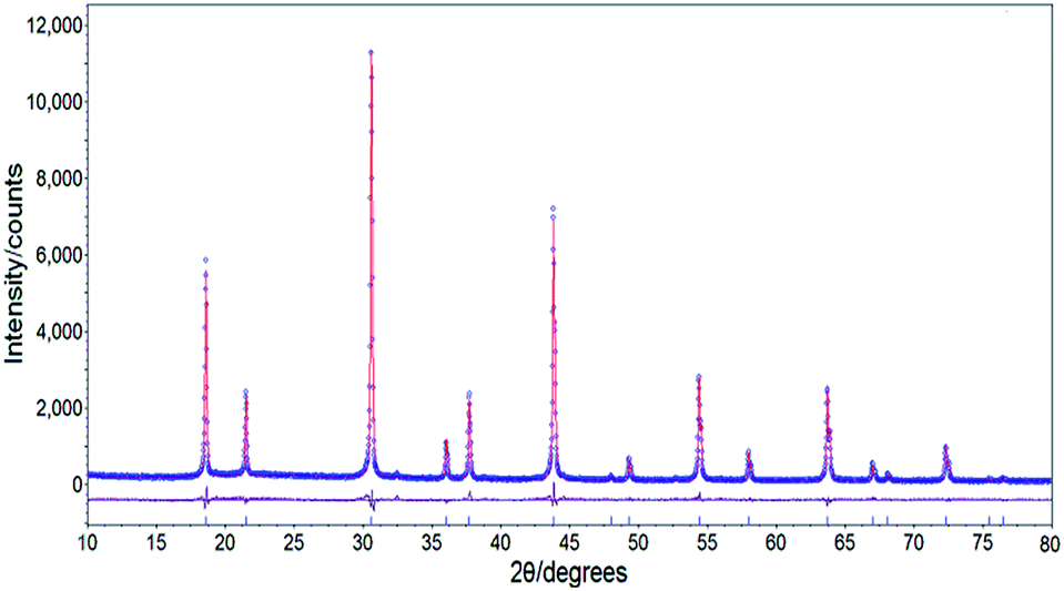 | ||
| Fig. 3 Observed (blue dots) and calculated (red line) powder XRD patterns as well as difference profile (grey line) for Rietveld refinements of K2NaGaF6. | ||
The photoluminescence excitation (PLE) and photoluminescence (PL) spectra of red phosphor K2NaGaF6:Mn4+ (1.76 mol% Mn4+) are shown in Fig. 4(a). There are two excitation bands in PLE spectra, centred at 355 nm and 466 nm when monitored at 630 nm. The broad excitation bands are attributed to the spin-allowed and parity-forbidden transitions 4A2g → 4T1g and 4A2g → 4T2g of Mn4+.7,31
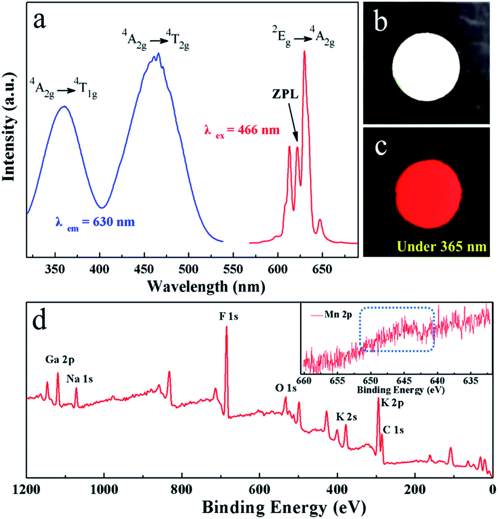 | ||
| Fig. 4 (a) PLE and PL spectra (1.76 mol% Mn4+), (b) image obtained under natural light (1.76 mol% Mn4+), (c) image obtained under UV-light (1.76 mol% Mn4+), and (d) XPS spectrum of K2NaGaF6:Mn4+ (1.76 mol% Mn4+). The inset is the magnification of Mn4+ part of the spectrum. | ||
Under the excitation of 466 nm, the K2NaGaF6:Mn4+ phosphors emit a series of narrow red emission lines located at 598 nm, 607 nm, 613 nm, 622 nm, 630 nm, 633 nm and 646 nm, which can be assigned to the transitions of anti-Stokes v3(t1u), v4(t1u), and v6(t2u), zero phonon line (ZPL), and Stokes v6(t2u), v4(t1u) and v3(t1u) vibronic modes respectively.25,26 In Fig. 4(a), it is obvious that the ZPL of K2NaGaF6:Mn4+ appears significantly stronger compared to K2SiF6:Mn4+ or K2GeF6:Mn4+ phosphor. Normally, the emission intensity of the ZPL is highly dependent on the local symmetry of Mn4+ surrounding. But, in this work it is attributed to the damage of symmetry of Mn4+ ion in K2NaGaF6 because of non-equivalent doping between Ga3+ and Mn4+.21 The phosphor colour is pale yellow and it emits an intense red light under blue light and UV light, as shown in Fig. 4(b) and (c).
The X-ray photoelectron spectroscopy (XPS) spectrum of K2NaGaF6:Mn4+ is shown in Fig. 4(d). The XPS spectrum depicts the potassium (K), sodium (Na), gallium (Ga), fluoride (F), and manganese (Mn) elements. There were little oxygen (O) and carbon (C) observed due to absorption of CO2 or H2O. Since the low concentration of Mn4+, its peak is not so obvious. Hence, a magnification of Mn part of the spectrum is provided in the inset to show Mn element clearly.
3.2 Electronic band structure
The electronic structure of K2NaGaF6 was calculated with the CASTEP module of the Materials Studio package, and the results are shown in Fig. 5(a) and b. Obviously, the calculated indirect band gap of K2NaGaF6 is approximately 5.92 eV, that indicates K2NaGaF6 is a good luminescent host due to its wide band gap.21 The top point on valence band and bottom point on conduction band both locate at the G point, which indicates that it is a direct band gap semiconductor. Fig. 5(b) shows the total and partial density of states (DOS) of K2NaGaF6. The conduction band is mainly composed by Ga/Na/K s and p orbitals, while the valence band is mainly composed by F 2p orbitals.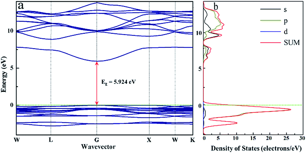 | ||
| Fig. 5 (a) Calculated energy band structure, (b) the total and partial density of states of K2NaGaF6. | ||
The UV-vis DRS of the representative non-doped K2NaGaF6 and Mn4+-doped K2NaGaF6 are displayed in Fig. 6. The slightly decreasing reflectance of non-doped K2NaGaF6 (black solid line) from 200 to 320 nm is the same as other reported fluoride phosphor.32–34
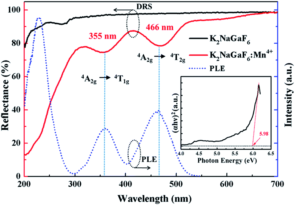 | ||
| Fig. 6 DRS of the non-doped and Mn4+-doped K2NaGaF6 and PLE of K2NaGaF6:Mn4+ (1.76 mol%). The inset shows the Tauc plot for the non-doped sample. | ||
The band gap is estimated according to eqn (1).
| (αhν)n = A(hν − Eg) | (1) |
In contrast with the non-doped host K2NaGaF6, the red phosphor K2NaGaF6:Mn4+ (1.76 mol%) sample has two intense absorption bands at ∼355 nm and ∼466 nm, which are due to the spin-allowed transition of 4A2g → 4T1g and 4A2g → 4T2g of Mn4+, respectively, as has also been clearly observed in the PLE spectrum. This result means that this phosphor can be effectively excited by blue InGaN chip, which shows great potential applications in W-LEDs.
3.3 Morphology and composition studies
The SEM and EDS analysis of K2NaGaF6:Mn4+ (1.76 mol%) show in Fig. 7. In Fig. 7(a), the synthesized K2NaGaF6:Mn4+ phosphor exhibited octahedral shaped crystals with particle size of 1.5–2.0 μm. The element contents were represented in the inset of Fig. 7(b). The atom ratios of K, Na, Ga, F are about 20.05%, 14.73%, 9.97%, 54.99% respectively, which is close to 2:1:1:6 ratio of K2NaGaF6.
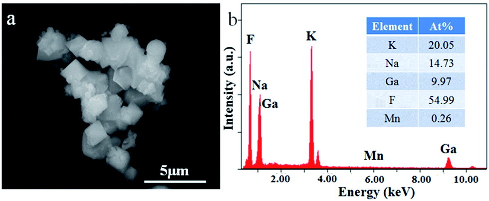 | ||
| Fig. 7 (a) SEM and (b) quantitative elemental composition data of K2NaGaF6:Mn4+ (1.76 mol%). | ||
3.4 Optimization of the reaction parameters
To optimize the photoluminescence properties of K2NaGaF6:Mn4+, the effects of Mn4+ concentration and aging time were systematically investigated. As shown in Fig. S1(a) and (b),† the XRD patterns indicate that all the phosphors with a Mn4+ molar concentration range from 0.82% to 3.30% and different aging durations are all pure phase. Fig. 8(a) shows the emission spectra of K2NaGaF6:Mn4+ with different doping concentration. Under 466 nm excitation, all the samples present a narrow red emission line centred at 630 nm. The relationship between integrated emission intensity and Mn4+-doping concentration in K2NaGaF6:Mn4+ is shown in the inset of Fig. 8(a). In order to confirm the real concentration of Mn4+ in K2NaGaF6, FAAS was used to measure the Mn4+ content in these samples and the results are listed in Table 1. The real concentration of Mn4+ in these samples is increased with the consumption of K2MnF6, and the emission intensity reaches maximum at the value of 1.76 mol%. Beyond this concentration, the luminescence intensity starts to fall due to the concentration quenching of Mn4+ in the K2NaGaF6 crystal lattice. Under 466 nm light excitation, K2NaGaF6:Mn4+ (1.76 mol%) presents a quantum efficiency of 61.8%, better than K2NaAlF6:Mn4+ with 58.4%.25 | ||
| Fig. 8 PL spectra of K2NaGaF6:Mn4+ with different doping concentration (a) and aging time (b). The inset in (a) and (b) show the integrated emission intensity of K2NaGaF6:Mn4+. | ||
It is well known that for phosphor particles, luminescence can be greatly affected by the crystallinity, surface defects, and doping concentration.36–39 For fluoride phosphors synthesized by co-precipitation method, particles are formed in a very short time. Therefore, a period of time is needed to modify the atom position and decrease surface defects. Aging as an effective way to obtain high crystallinity and low surface defect crystals is an important approach to optimize PL properties of fluoride phosphor. The K2NaGaF6:Mn4+ phosphors in HF solution were aged in ice-water to improve the crystallinity of the particles. Fig. 8(b) shows the emission spectra of K2NaGaF6:Mn4+ red phosphors obtained after different aging times. The emission intensity of K2NaGaF6:Mn4+ reaches a maximum after 4 h reaction. Then the emission intensity invariant as the aging time increases further. From Fig. S2,† it is clearly that the crystallinity of K2NaGaF6:Mn4+ particles can be improved by increasing the aging time. With the prolonging of aging time, the particle size and shape of K2NaGaF6:Mn4+ changed gradually. The particle size increased from 0.7 μm to 2 μm and the morphology transformed from sphere to octahedron gradually. The crystal size of K2NaGaF6:Mn4+ particles with less than 1 h aging time are much small, and their octahedron sharps are also not clear. With more than 4 h aging time, particles show higher crystallinity and better luminescence properties. The K2NaGaF6:Mn4+ particles are composed of octahedral shaped crystals featured by clear edges and corners. It is believed that the optimal reaction conditions to obtain the red light K2NaGaF6:Mn4+ are about 4 h aging time with 1.76 mol% Mn4+ concentration.
Fig. 9 shows the concentration-dependent PL decay curves of Mn4+ in K2NaGaF6:Mn4+ red phosphors under 466 nm blue light excitation, the relationship between Mn4+ doping concentration and lifetime was shown in inset. The PL decay time was fitted based on a single-exponential function. As is shown in Fig. 9, the lifetimes of Mn4+ decay from 4.24 ms to 2.35 ms along with increasing of Mn4+ concentration from 0.82 mol% to 3.3 mol%. However, when the doping concentration of Mn4+ more than 2.1 mol%, the PL decay curves deviated the single-exponential decay trend. That can be explained by the serious non-radiative transition processes among the Mn4+ ions at a high Mn4+ concentration level.
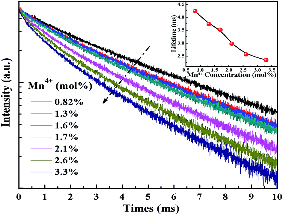 | ||
| Fig. 9 Room temperature PL decay curves of K2NaGaF6 doped with different Mn4+ concentration. The inset shows the lifetimes of K2NaGaF6:Mn4+. | ||
3.5 LED application
In order to understand the features of K2NaGaF6:Mn4+ red phosphor and its application in the devices of warm W-LEDs, we fabricated a warm W-LED using a blue LED chip combined with the commercial yellow YAG:Ce3+ phosphor and the synthesized K2NaGaF6:Mn4+ (1.76 mol% Mn4+) red phosphor. Fig. 10(a) shows the current-dependent LED performance of this combined device. The sharp red emission of K2NaGaF6:Mn4+ red phosphor at ∼633 nm can be observed clearly in this electroluminescence (EL) spectra. The broad band centred at ∼550 nm belongs to the emission of the YAG:Ce3+ yellow phosphor and the sharp peak at ∼460 nm can be attributed to the emission of the InGaN chip.12,19,31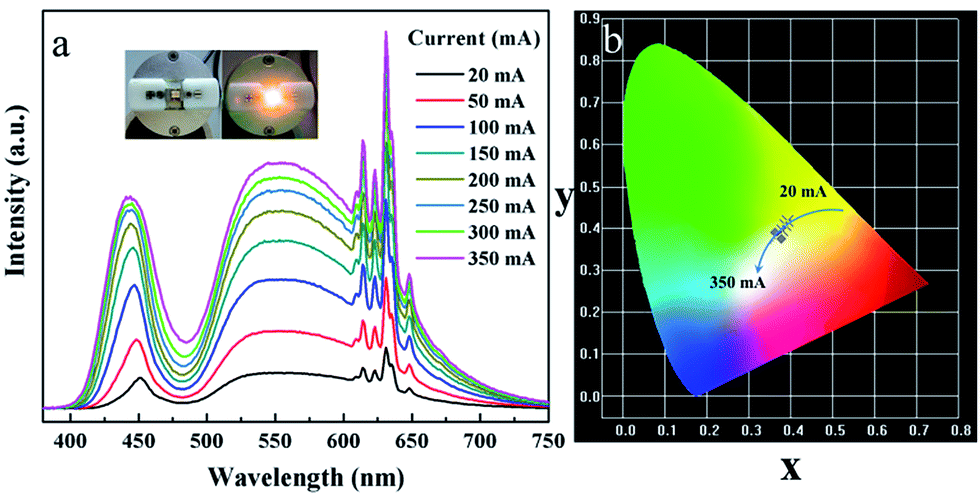 | ||
| Fig. 10 (a) Electroluminescence spectra and (b) CIE chromaticity diagram of fabricated white LED under various drive currents. | ||
From Fig. 10(a), it is obviously that there is no remarkable change on band shapes and positions of emission peaks when the drive current increases from 20 to 350 mA. Moreover, the emission intensity increased with the increasing driven current. All these results indicate this warm W-LED has a good stability in CRI and CCT. Photographs of the W-LED device are shown in the inset image of Fig. 10(a). Owing to the red light in the emission spectrum, a noticeable warm light emission can be observed. The chromaticity coordinates value under different currents are labelled in Fig. S3† and CIE chromaticity diagram Fig. 10(b). The Ra and CCT values of this W-LED are 81.6 and 3643 K respectively. Moreover, the colour tolerance adjustment (CTA) of this W-LED is 6.4 SDCM, which is very close to the commercial standard. All these results indicate the potential of K2NaGaF6:Mn4+ phosphor as red component for W-LEDs application.
4. Conclusions
In summary, a highly efficient novel ternary-alkaline red emitting fluoride phosphor, K2NaGaF6:Mn4+, has been successfully synthesized through co-precipitation method at room-temperature. The K2NaGaF6 host has a cubic unit cell with the space group Fmm and lattice parameters of a = 8.2577 (4) Å, Z = 4, Vcell = 563.08 (8) Å3. The band gap is approximately 5.92 eV calculated with the CASTEP, which very is close to the experimental result (5.98 eV). The morphology of phosphor shows a shape of octahedral crystals and the size is 1.5–2 μm. Under 466 nm excitation, the phosphor emits a series of narrow band emission lines centred at 630 nm. The PL properties of the K2NaGaF6:Mn4+ red phosphors were optimized with different Mn4+ concentrations and aging times. Based on its excellent PL properties, a white-light-emitting diode was fabricated by a blue LED chip combined with commercial yellow YAG:Ce3+ phosphor and the synthesized K2NaGaF6:Mn4+ red phosphor. The CCT and Ra value of this device reach 3643 K and 81.6 respectively. All these results imply that the K2NaGaF6:Mn4+ red phosphor has potential applications in warm W-LEDs.
Conflicts of interest
There are no conflicts to declare.Acknowledgements
The Project was sponsored by the National Natural Science Foundation of China (21401122, 51272151, and 51672167), the Natural Science Foundation of Shaanxi Province (2014JZ002, 2015JQ2041), Fundamental Research Funds for the Central Universities (GK201603050, GK201703020, and GK201701011), and Science and Technology program of Xi'an (2017071CG/RC034(SXSF004)).References
- A. Lazarowska, S. Mahlik, M. Grinberg, C. C. Lin and R. S. Liu, J. Chem. Phys., 2015, 143, 134704 CrossRef CAS PubMed.
- Y. Jin, M. H. Fang, M. Grinberg, S. Mahlik, T. Lesniewski, M. G. Brik, G. Y. Luo, J. G. Lin and R. S. Liu, ACS Appl. Mater. Interfaces, 2016, 8, 11194–11203 CAS.
- H.-D. Nguyen, C. C. Lin, M.-H. Fang and R.-S. Liu, J. Mater. Chem. C, 2014, 2, 10268–10272 RSC.
- L. Lv, X. Jiang, S. Huang, X. a. Chen and Y. Pan, J. Mater. Chem. C, 2014, 2, 3879–3884 RSC.
- R. Kasa and S. Adachi, J. Electrochem. Soc., 2012, 159, J89 CrossRef CAS.
- C. C. Lin, A. Meijerink and R. S. Liu, J. Phys. Chem. Lett., 2016, 7, 495–503 CrossRef CAS PubMed.
- L. Huang, Y. Zhu, X. Zhang, R. Zou, F. Pan, J. Wang and M. Wu, Chem. Mater., 2016, 28, 1495–1502 CrossRef CAS.
- Q. Zhou, Y. Zhou, Y. Liu, Z. Wang, G. Chen, J. Peng, J. Yan and M. Wu, J. Mater. Chem. C, 2015, 3, 9615–9619 RSC.
- W.-L. Wu, M.-H. Fang, W. Zhou, T. Lesniewski, S. Mahlik, M. Grinberg, M. G. Brik, H.-S. Sheu, B.-M. Cheng, J. Wang and R.-S. Liu, Chem. Mater., 2017, 29, 935–939 CrossRef CAS.
- L.-L. Wei, C. C. Lin, M.-H. Fang, M. G. Brik, S.-F. Hu, H. Jiao and R.-S. Liu, J. Mater. Chem. C, 2015, 3, 1655–1660 RSC.
- L. Y. Wang, E. H. Song, Y. Y. Zhou, T. T. Deng, S. Ye and Q. Y. Zhang, J. Mater. Chem. C, 2017, 5, 7253–7261 RSC.
- F. Tang, Z. Su, H. Ye, M. Wang, X. Lan, D. L. Phillips, Y. Cao and S. Xu, J. Mater. Chem. C, 2016, 4, 9561–9568 RSC.
- H. F. Sijbom, J. J. Joos, L. I. D. J. Martin, K. Van den Eeckhout, D. Poelman and P. F. Smet, ECS J. Solid State Sci. Technol., 2015, 5, R3040–R3048 CrossRef.
- X. Li, X. Su, P. Liu, J. Liu, Z. Yao, J. Chen, H. Yao, X. Yu and M. Zhan, CrystEngComm, 2015, 17, 930–936 RSC.
- Y. Arai and S. Adachi, J. Electrochem. Soc., 2011, 158, 179 CrossRef.
- Q. Zhou, Y. Zhou, Y. Liu, L. Luo, Z. Wang, J. Peng, J. Yan and M. Wu, J. Mater. Chem. C, 2015, 3, 3055–3059 RSC.
- J. S. Zhong, D. Q. Chen, X. Wang, L. F. Chen, H. Yu, Z. G. Ji and W. D. Xiang, J. Alloys Compd., 2016, 662, 232–239 CrossRef CAS.
- E. H. Song, J. Q. Wang, S. Ye, X. F. Jiang, M. Y. Peng and Q. Y. Zhang, J. Mater. Chem. C, 2016, 4, 2480–2487 RSC.
- E. Song, J. Wang, J. Shi, T. Deng, S. Ye, M. Peng, J. Wang, L. Wondraczek and Q. Zhang, ACS Appl. Mater. Interfaces, 2017, 9, 8805–8812 CAS.
- P. Rawat, S. Kumar Saroj, M. Gupta, G. Vijaya Prakash and R. Nagarajan, J. Fluorine Chem., 2017, 200, 1–7 CrossRef CAS.
- T. T. Deng, E. H. Song, J. Sun, L. Y. Wang, Y. Deng, S. Ye, J. Wang and Q. Y. Zhang, J. Mater. Chem. C, 2017, 5, 2910–2918 RSC.
- T. Deng, E. H. Song, Y. Y. Zhou, L. Y. Wang, S. Ye and Q. Zhang, J. Mater. Chem. C, 2017, 5, 9588–9596 RSC.
- Y. Zhu, J. Yu, Y. Liu, M. G. Brik, L. Huang, T. Xuan and J. Wang, RSC Adv., 2017, 7, 30588–30593 RSC.
- Y. Zhu, L. Cao, M. G. Brik, X. Zhang, L. Huang, T. Xuan and J. Wang, J. Mater. Chem. C, 2017, 5, 6420–6426 RSC.
- L. Y. Wang, E. H. Song, T. T. Deng, Y. Y. Zhou, Z. F. Liao, W. R. Zhao, B. Zhou and Q. Y. Zhang, Dalton Trans., 2017, 46, 9925–9933 RSC.
- D. Li, W. Qin, P. Zhang, S. Xiao and L. Wang, CrystEngComm, 2016, 18, 6908–6913 RSC.
- M. C. M. De Lucas, J. M. Dance, F. Rodríguez, A. Tressaud, M. Moreno and J. Grannec, Radiat. Eff. Defects Solids, 2006, 135, 19–22 CrossRef.
- M. G. Brik and K. Ogasawara, Phys. Rev. B: Condens. Matter Mater. Phys., 2006, 74, 045105 CrossRef.
- Y. Zhu, Y. Liu, L. Huang, T. Xuan and J. Wang, Sci. China: Technol. Sci., 2017, 6420–6426 CAS.
- M. D. Segall, P. J. D. Lindan, M. J. Probert, C. J. Pickard, P. J. Hasnip, S. J. Clark and M. C. Payne, J. Phys.: Condens. Matter, 2002, 14, 2717–2744 CrossRef CAS.
- M. J. Lee, Y. H. Song, Y. L. Song, G. S. Han, H. S. Jung and D. H. Yoon, Mater. Lett., 2015, 141, 27–30 CrossRef CAS.
- Z. Yang, Q. Wei, M. Rong, Z. Yang, Z. Wang, Q. Zhou and Q. Wang, Dalton Trans., 2017, 46, 9451–9456 RSC.
- L. F. Lv, X. Y. Jiang, S. M. Huang, X. Chen and Y. X. Pan, J. Mater. Chem. C, 2014, 2, 3879–3884 RSC.
- Q. Zhou, H. Y. Tan, Y. Y. Zhou, Q. H. Zhang, Z. L. Wang, J. Yan and M. M. Wu, J. Mater. Chem. C, 2016, 4, 7443–7448 RSC.
- K. Inaba, S. Suzuki, Y. Noguchi, M. Miyayama, K. Toda and M. Sato, Eur. J. Inorg. Chem., 2008, 35, 5471–5475 CrossRef.
- J. Zhuang, X. Zhang, G. Wang, D. Li, W. Yang and T. Li, J. Mater. Chem., 2003, 13, 1853–1857 RSC.
- X. Zhang, J. Yu, J. Wang, B. Lei, Y. Liu, Y. Cho, R.-J. Xie, H.-W. Zhang, Y. Li, Z. Tian, Y. Li and Q. Su, ACS Photonics, 2017, 4, 986–995 CrossRef CAS.
- A. Wang, X. Yan, M. Zhang, S. Sun, M. Yang, W. Shen, X. Pan, P. Wang and Z. Deng, Chem. Mater., 2016, 28, 8132–8140 CrossRef CAS.
- Z. Liang, S. Zhao, Z. Xu, B. Qiao, P. Song, D. Gao and X. Xu, ACS Appl. Mater. Interfaces, 2016, 8, 28824–28830 CAS.
Footnote |
| † Electronic supplementary information (ESI) available. See DOI: 10.1039/c7ra10274g |
| This journal is © The Royal Society of Chemistry 2017 |