
 Open Access Article
 This Open Access Article is licensed under a
 Creative Commons Attribution 3.0 Unported Licence
Molecular dynamics simulation of the mechanical properties of multilayer graphene oxide nanosheets
Xu Zhanga,
Shuyan Liuab,
Han Liub,
Jinwen Zhang c and
Xiaoning Yang*a
c and
Xiaoning Yang*a
aState Key Laboratory of Material-Oriented Chemical Engineering, College of Chemical Engineering, Nanjing Tech University, Nanjing 210009, China. E-mail: Yangxia@njtech.edu.cn
bApparel, Merchandising, Design and Textiles Composite Materials and Engineering Center, Washington State University, Pullman, WA 99164, USA
cSchool of Mechanical and Materials Engineering, Composite Materials and Engineering Center, Washington State University, Pullman, WA 99164, USA
First published on 4th December 2017
Abstract
Multilayer graphene oxide (GO) is an attractive candidate for new applications in nanoelectromechanical materials and structural reinforcement nanocomposites due to its strong mechanical properties. In this study, the mechanical properties and failure mechanism of multilayer GO nanosheets were studied by non-equilibrium molecular dynamics simulation. The simulated Young's modulus, fracture stresses, and fracture strains were found to be consistent with the experimentally measured values. The effects of the surface oxidation content of GO and the stacking layer number on these mechanical properties were investigated. The oxidation content has a larger influence on the mechanical properties compared with the layer number. The failure of multilayer GO nanosheets undergoes a relatively slow cracking process due to the existence of functional groups and the stacking layers. There appears to be different two-dimensional stress distributions on multilayer GO sheets from the outer layer to inner layer. The Young's modulus and the fracture strength of the middle layer are generally larger than those in the outer layer. The fracture of the outside GO sheet begins first, and then the failure of the inner GO sheet occurs with a delayering process. The simulation result is expected to improve understanding of the mechanical behavior of multilayer GO nanosheets.
Introduction
Graphene oxide (GO) inherits the two-dimensional structure of graphene, but contains surface functional groups, mainly including hydroxyl and epoxy groups in the plane, as well as carbonyl and carboxyl groups on the edge.1 Different from monolayer GO nanosheets2–4 and GO paper, GO nanosheets5–7 exhibit unique properties due to their intermediate transition structure and have promising applications in a wide range of fields, such as in structural reinforced composites,8–10 super capacitors,11 flexible electronic materials,12,13 and biology.14 For GO nanosheets, excellent mechanical properties such as high strength and strong toughness are generally essential. To further promote the development of GO in engineering applications by regulating the structure of GO, it is necessary to have a good understanding of its mechanical behavior.At present, a considerable number of experiments have been conducted to measure the mechanical properties of monolayer GOs and GO paper.2,4,15,16 There is a significant difference in the mechanical properties of GO materials on various thickness scales. For example, when the thickness of GO was reduced, the elastic modulus increases rapidly. Different fracture mechanisms have been proposed for monolayer GO and GO papers. It is generally accepted that the fracture of monolayer GO shows an intraplanar structure cleavage,16 whereas GO paper typically fails by an interplanar delamination and shear deformation.4 Molecular simulation17,18 has been applied to study the mechanical behavior of single-layer GO sheets. It has been found that the relative concentration of hydroxyl and epoxide groups has larger effect on the deformation and failure behavior of single-layer GO. Mechanical properties of single-layer GO sheet with different types of functional groups have been simulated, respectively, to characterize the effect of functionalization. However, these functional groups can not represent the structure and composition on actual GO sheets. Currently, very limited works have been reported for the mechanical properties of multilayered GO nanosheets. It is highly interest to recognize the different mechanical properties and fracture mechanisms between single-layer and multilayer GO sheets. Wang19 et al. provided the preliminary study on fracture behavior of multilayer GO, in which, only single stress–strain curve was characterized with insufficient fracture mechanism. In a recent study,20 the overall strength and fracture behavior of GO nanosheets were experimentally examined. This study demonstrated the inherent defects and precracked layer determined the fracture behavior of actual GO materials. However, these actual defects might disguise the essential mechanical behavior. Currently, the mechanical properties and fracture mechanism of defect-free GO nanosheets still remains largely unexplored.
In this paper, Reaxff-based molecular dynamic (MD) simulations were performed to comprehensively investigate the mechanical properties of multilayer GO nanosheets. The fracture behavior of each single layer in the multilayer GO has been separately revealed. The different fracturing performance for individual single layer in the GO nanosheets has been displayed. Various thicknesses of GO nanosheets were considered and the effects of both functional groups and layer number of GO sheet were investigated.
Methodology and simulation details
The Large-scale Atomic/Molecular Massively Parallel Simulator (LAMMPS)21 was utilized to perform the MD simulation. We describe the bonded and nonbonded interaction between different atoms in the GO systems with ReaxFF potential.22–24 The potential energy in Reaxff field includes several different components as following:| Esystem = Ebond + Eover + Eunder + Eval + Epen + Etors + Econj + EvdWalls + ECoulomb | (1) |
Representative GO nanosheets were chosen with a planar dimension of 4.7 nm by 4.7 nm and various thicknesses, depending on the number of stacking layers. The hydroxyl and epoxy functional groups randomly and uniformly distributed on the both sides of the basal plane of GO, based on the Lerf–Klinowski model,25 in which the ratio of hydroxyl groups and epoxy groups was set to be 1![[thin space (1/6-em)]](https://www.rsc.org/images/entities/char_2009.gif) :1. The carbonyl and carboxyl groups on the edge of GO plane were not considered in this study. These groups have weak effects on the mechanical properties because they only represent small portion of atoms with dangling bonds only attached to plane edge.26 In the present work, we did not consider the interlayer water molecules, because the main goal of this work is to study the intrinsic mechanical behavior of multilayer GO by comparing with single-layer GO. It has been found that the elastic modulus determined by the interlamellar hydrogen bond network, which was mediated by functional groups and water molecule, is relatively weak compared with the intrinsic stiffness of the GO sheets.7 We constructed 5 structure models stacking with one to five layers of GO nanosheets, named with GO-I, GO-II, GO-III, GO-IV, GO-V, respectively. We used five different oxidation contents from 20% to 40%, which is defined as the oxygen-to-carbon ratio26 for the different stacking layers of GO nanosheets.
:1. The carbonyl and carboxyl groups on the edge of GO plane were not considered in this study. These groups have weak effects on the mechanical properties because they only represent small portion of atoms with dangling bonds only attached to plane edge.26 In the present work, we did not consider the interlayer water molecules, because the main goal of this work is to study the intrinsic mechanical behavior of multilayer GO by comparing with single-layer GO. It has been found that the elastic modulus determined by the interlamellar hydrogen bond network, which was mediated by functional groups and water molecule, is relatively weak compared with the intrinsic stiffness of the GO sheets.7 We constructed 5 structure models stacking with one to five layers of GO nanosheets, named with GO-I, GO-II, GO-III, GO-IV, GO-V, respectively. We used five different oxidation contents from 20% to 40%, which is defined as the oxygen-to-carbon ratio26 for the different stacking layers of GO nanosheets.
Prior to the uniaxial tensile loading of the GO nanosheets, we firstly made the initial GO model to a local minimum configuration with a conjugate-gradient algorithm. The system was then heated to 300 K with the Nose–Hoover thermostat and relaxed at this temperature for 25 ps to bring the system into an equilibrated configuration. As shown in the Fig. 1, during the heating and relaxation process, the periodic boundary was performed along the in-plane of GO nanosheets, and the out-plane of GO nanosheets was free.20 The boundary condition was selected to eliminate large undulations associated with free planar edges.26 A time step of 0.25 fs was used for all MD simulation. As shown in the Fig. 1, uniaxial tensile loading was applied by dilating the GO nanosheets under an equal affine transformation to atom position with dilating the simulation cell along the loading direction.20 This deformation methodology is equivalent to uniaxial tensile loading along the loading direction. We carried out the uniaxial tensile loading of GO nanosheet with a constant strain rate of 0.0001 ps−1. In the uniaxial tensile simulation, the stress was calculated as27
 | (2) |
 | ||
| Fig. 1 (a) Schematic of the initial structures in the MD supercell of multi-layers graphene oxide nanosheets system in crossing section (b) typical configuration of the graphene oxide nanosheet for in-plane tension simulation, structures of the basal plane and the distribution of functional groups. The principal directions of the basal plane are indicated in the figure. Loading is performed along the armchair direction which is normalized against the assumed interlayer spacing. | ||
Result and discussion
At first, the uniaxial tensile simulation of a series of monolayer GOs with different oxidation contents was carried out along the directions of armchair and zigzag. We obtained the corresponding Young's modulus, fracture strength, and fracture strain respectively. As shown in Fig. 2, the Young's modulus of monolayer GO generally decreases with the increase of oxidation content, decreasing from ∼450 GPa at 20% of oxidation content to about ∼200 GPa at 40%. The results agree well with the experimentally measured values of 250 ± 150 GPa by Gomez-Navarro et al.29 and 207.6 ± 23.4 GPa by Suk et al.,15 as well as the previously simulated values.17,30 This monotonous decrease of Young modulus with the oxidation content can be explained as the fact that the addition of oxygen-containing groups makes the strong sp2 carbon bonds transform to weak hybrid sp3 carbon bonds, thereby reducing the energy stability of GO basal plane.17,18,30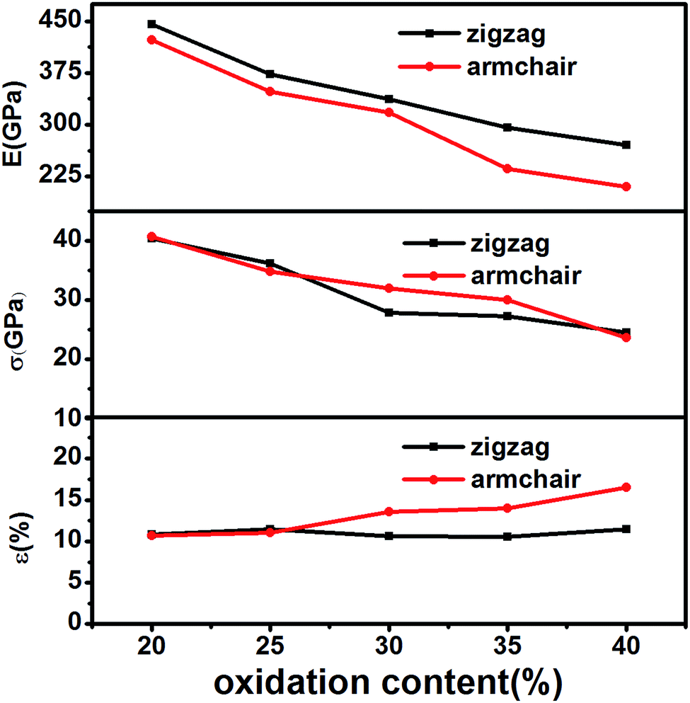 | ||
| Fig. 2 The calculated mechanical properties of monolayer graphene oxide with oxidation content from 20% to 40% along both zigzag and armchair directions. (a) Young's modulus (b) fracture strength (c) fracture strain. | ||
As shown in Fig. 2(a), the Young's modulus in armchair direction is slightly less than that in zigzag direction, which is probably due to different random arrangement of epoxide groups on GO plane. For example, if the epoxy groups, attached on the C–C bonds parallel to the armchair direction, have larger proportion than those attached on other C–C bonds, this arrangement of epoxy functional groups could lead to the increase of fracture strain along the armchair direction. However, the discrepancy of Young's modulus between the two directions can be negligible, comparing to the effect of oxidation content. This insensibility of chirality for Young's modulus of monolayer GO sheet has been similarly observed in previous researches.17,19
As expected, we find that the fracture strength (Fig. 2(b)) of monolayer GO decreases with the oxidation content. This is in good agreement with the previous results.18 Fig. 2(c) shows the fracture strain of GOs under various contents of oxidation is in the range of 10–16%. This result conforms to the simulated results of 10–15%,19,30 as well as the measured values of 10–13%.19 In short, the simulated mechanical properties of monolayer GO in this work are in good agreement with the previous reference results.
In this work, we mainly simulated the mechanical properties of multilayer GOs. Herein, we only conducted uniaxial tensile simulation along the armchair direction. Fig. 3(a) shows the typical stress–strain curve under uniaxial loading for the 5-layer stacked GO nanosheets (GO-V) with the oxidation content of 25%. The stress–strain curve can visually capture the changes in the stress with the strain during the tensile process. In the stress–strain curve, point A, B, and C represent the characteristic points on the tensile process. The stress–strain curve before point A shows the linear elastic behavior of GO with small strain, and the carbon structure on the basal plane was not destroyed yet. As the strain increases, the plastic deformation appeared with the crack and defects of the GO nanosheets after the point A. The maximum stress of the multilayer GO nanosheets corresponds to the point B, after which the stress decreases slowly with the strain.
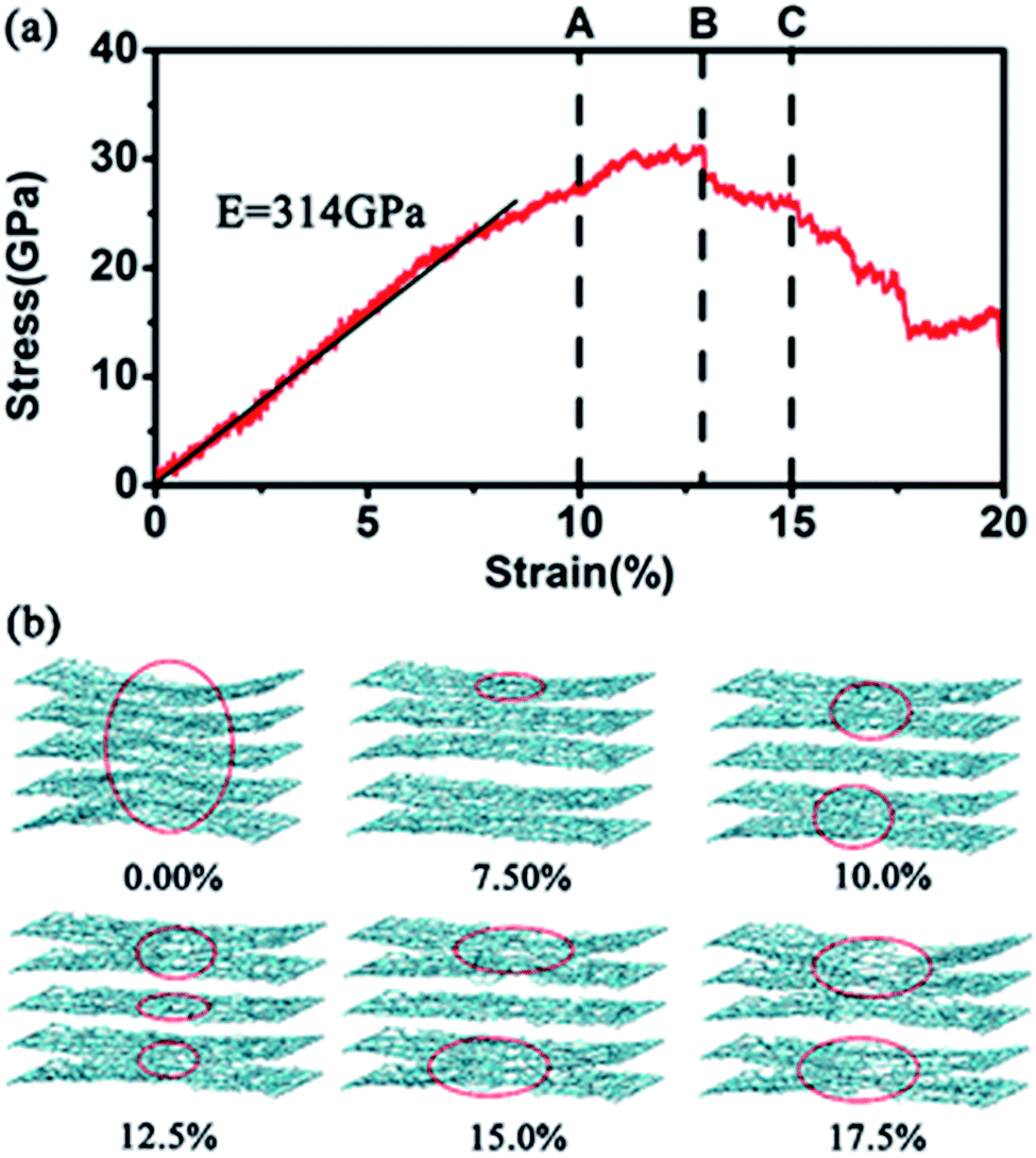 | ||
| Fig. 3 (a) Representative stress–strain curve of five stacked layers GO nanosheets. Young's modulus is fitted to the initial and linear regime of stress–strain curve. (b) Atomistic carbon basal plane snapshots of the six typical points during the tensile deformation processes along the armchair direction. The red circles are used to denote the crack and fracture zones. | ||
The Young's modulus was determined by fitting the linear region of the loading stress–stress curve.20 Meanwhile, the fracture strength and fracture strain were generally defined as the point when the tensile stress reaches the maximum value.31 For the 5-layer stacked GO nanosheets under the oxidation content of 25%, the simulated Young's modulus is ∼314 GPa, and the fracture strength is ∼31 GPa. Cao et al.20 performed a tensile test on multilayer GO nanosheets by using SEM in microeletromechanical systems (MEMS). The Young's modulus and the fracture strength for five GO samples with thickness ranging from 75 ± 13 nm to 24 ± 4 nm were found to be 103–291 GPa and 4–11 GPa, respectively. Although our simulated mechanical properties of GO nanosheets are generally larger than the experimental values, both of them exhibit the same order of magnitude. The main reason for this discrepancy is the existing structural defect in real GO nanosheets,13,14 which can cause attenuation of GO strength. Meanwhile, the jagged stacking feature of actual GO nanosheets also causes a decrease of mechanical properties.
Upon reaching the maximum tensile stress, the stress–strain curve of GO-V demonstrates slow and smooth decline after the failure point, which is obviously different from that observed in monolayer GO. Generally, monolayer GO undergoes drastic and brittle failure near maximum loading31 for hydroxyl-rich GOs and ductile deformation for epoxide-rich GOs, which is due to the epoxide-to-ether transformation, thus leading to the wave-like fracture behavior. This distinguished tensile performance of multilayer GO nanosheets is probably caused by the mutual interference between the neighboring layers. In addition, it is noted that the wave-like fracture behavior of the simulated multilayer GO stress–strain curve in this work is also distinct from the previous reported result,19 in which the large brittle behavior has been observed. We can conclude that the increased percentage of hydroxyl groups used in the previous work19 might cause GO to behave as a brittle material.
Fig. 3(b) shows a snapshot of the overall structural evolution of 5-layer GO nanosheets under different strains. It can be observed that failure occurs along each layer plane without interlayer cleavage. This is in agreement with the experimental observation that the mechanical failure of GO nanosheets occurred by intraplanar facture of individual layers.20 In addition, the fracture feature of each layer in the multilayered GO nanosheet is not synchronous. From 10% to 15% in the fracture strain, the outer layer of GO nanosheets first breaks. As shown in Fig. 3(b), when stretching to the strain of 10%, the outer layer carbon (red circles) in the basal plane began to break and then the broken area increased. The obvious breakage of inner layer appeared when stretching to 12.5%. When the strain is up to 17.5%, the overall GO nanosheets fractured. This asynchronous behavior is probably due to interlayer interaction in the multilayer stacked structure, in which the inner layers possess relative stronger cooperative interactions with neighboring layers. In addition, during the tensile process, functional groups were found to reorganize and aggregate, leading to distortion in the gallery space of GO nanosheets. This has been similarly observed in the previous work.32
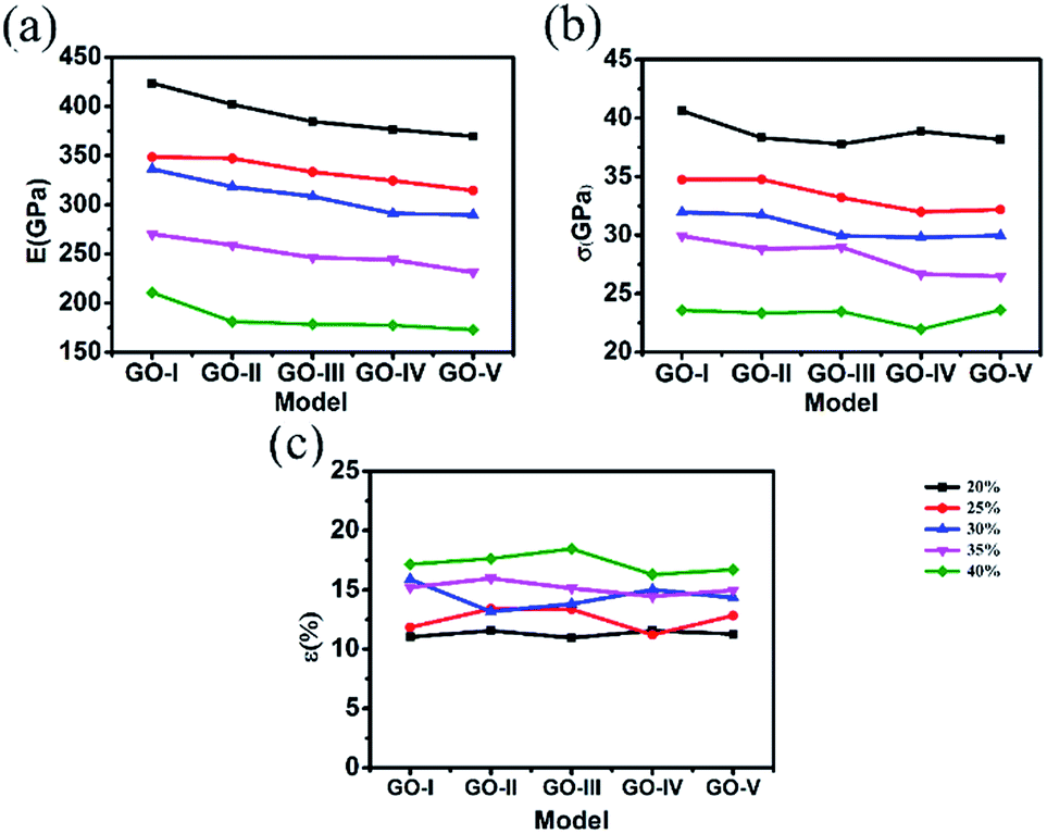
In order to further explore the effect of stacking level number on the tensile behavior of GO nanosheets, a series of multilayer GO sheets with various thicknesses of GO sheets, from 1 to 5 stacking layers, denoted as GO-I, GO-II, GO-III, GO-IV, and GO-V respectively, have been simulated. Fig. 4 shows the comparison of mechanical properties for these GO nanosheets. Overall, for all the multilayer GO nanosheets, the stiffness and strength decrease with the oxidation content. The fracture strain shows certain oscillation with the oxidation content. These mechanical properties are similar with those observed in monolayer GO sheet.17,19,30
 | ||
| Fig. 4 The calculated mechanical properties of a series of GO samples with varied oxidation contents and stacked layers. (a) Young's modulus, (b) fracture stress, (c) fracture strain. | ||
As seen from Fig. 4(a), the Young's modulus of GO nanosheets decreases to some extent with the number of layers increasing. This indicates that enhanced number of layers could produce inhibitive effect on the Young's modulus of GO nanosheets. Comparatively, as shown in Fig. 4(b), the fracture strain and fracture strength do not show obvious changing trend with the layer number. Under the uniaxial tension, the fracture stress of the multilayer GO nanosheets has similar strength to monolayer GOs. Meanwhile, the fracture strain of GO nanosheets also maintains certain fluctuating level from 11% under the lower oxidation content (20%) to 17% under the higher oxidation content (40%). This fracture strain of multilayer GO nanosheets is in good agreement with the experimental values (8–15%) by Cao et al.20
Fig. 5 shows the corresponding comparison of mechanical properties of each sheet in the 5-layer stacked GO nanosheets (GO-V). On the whole, the Young's modulus and fracture strength for each sheet of the five-layer GO decrease as the oxidation content increases, which are similar to those for monolayer GO.17,30 This result means that the effect of stacking on the mechanical properties of GO is relatively weak, as compared with the oxidation content.
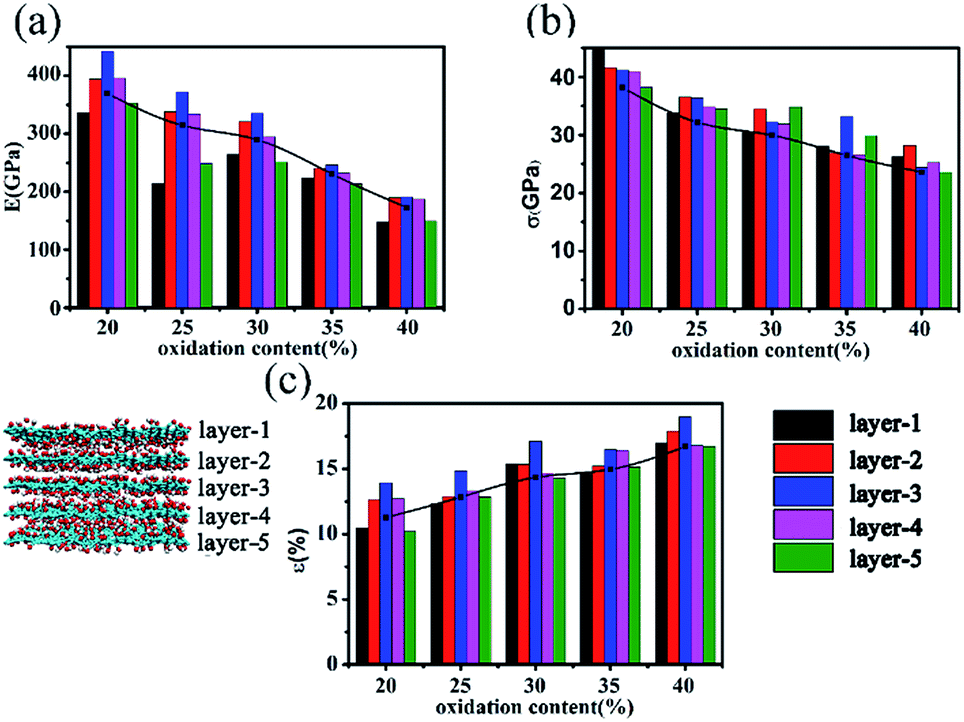 | ||
| Fig. 5 (a) Young's modulus, (b) fracture stress, (c) fracture strain of each single layer of 5-layer GO nanosheets with oxidation content from 20% to 40%. | ||
Further inspection of Fig. 5(a) shows that the Young's modulus of middle layer is slightly larger than that in the outer layer. Similar observation has been found for the fracture strain of individual GO sheet. This is consistent with the preceding observation that the fracture evolution process of each layer in multilayer GO nanosheets is not synchronized and the outer sheet of multilayer GO breaks firstly. This also confirmed that the fracture evolution process of multilayer GO is different from monolayer GO.
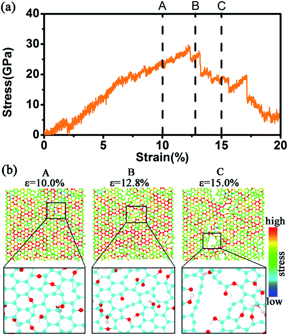
We further computed the stress–strain curves of each single layer in the 5-layer stacked GO nanosheets and analyzed the change of surface atomic structure. Fig. 6–8 show the stress–strain curves and the corresponding stress change during the tensile processes for the first layer (layer-1), second layer (layer-2), and third layer (layer-3), respectively, in the 5-layer stacked GO (GO-V). For comparison, we also labeled the three characteristic pints (A, B, C) in the stress–strain curves, which have been used in Fig. 3(a) in the tensile process of GO-V.
Fig. 6(a) shows the strain–strain curve of the layer-1, in which the fracture occurs under the overall strain of ∼12.3%, which is before the breaking point B of the GO-V. However, the layer-2 started to crack after the point B (Fig. 7(a)) with the fracture strain ∼13%. Furthermore, in Fig. 8(a), the stress of layer-3 reaches the rupture point when loaded to ∼14.8%, which is further behind the point B. As a result, we can observe that, when the layer-1 reaches the maximum stress point (∼30 GPa), the stress in the layer-2 and the layer-3 continues to increase. When the layer-2 attains the fracture point (∼34 GPa), the stress of layer-3 continues to increase. The fracture behavior of individual layer in the 5-layer GO is developed from the outer sheet (layer-1) to the inner sheet (layer-3), displaying delayed breakage for each layer.
 | ||
| Fig. 6 (a) Stress–strain curve for the first layer (layer-1) in the five-stack GO nanosheet; (b) the surface two-dimensional (2-D) stress distribution of the layer-1 of typical points during the tensile process and the enlarging local atomistic snapshots to denote the structural changes. All atoms are colored to represent the stress magnitude. | ||
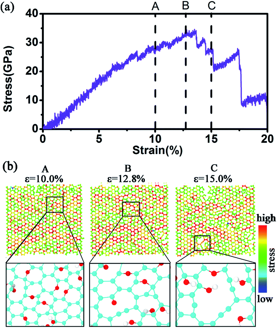 | ||
| Fig. 7 Same as Fig. 6 but for the layer-2 sheet. | ||
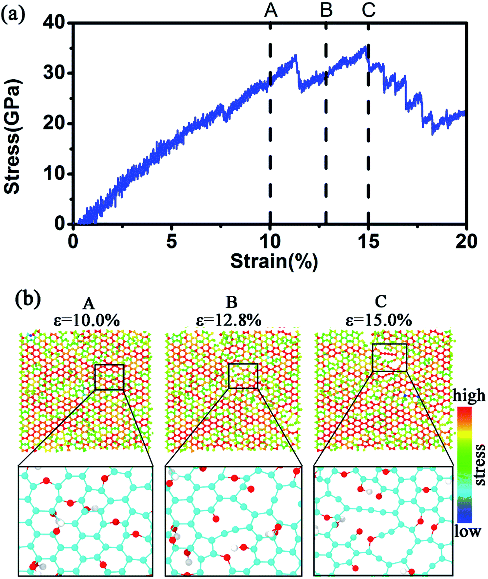 | ||
| Fig. 8 Same as Fig. 6 but for the layer-3 sheet. | ||
The upper panel in Fig. 6(b) further shows the surface two-dimensional (2-D) stress distribution of the layer-1 during the tensile process. At the whole strain of 10% for the GO-V, which is before the breakage strain, larger yellow and red regions appear in the 2-D stress diagram, suggesting the existence of higher stress on the layer-1 sheet. This is because, at this stage, there appears to be a large portion of sp2 bonds on this plane, which could withstand applied stress loading. From the corresponding configuration (low panel in Fig. 6(b)), it was observed that for the first GO layer in the early tensile process, epoxide group can transform into ether group (C–O–C) by cleavage of the C–C bond associated with epoxide rings. At this stage, the skeleton structure on the basal plane of GO has not been broken yet, so the stress continues to increase. The flexible ether bond allows GO to tolerate greater deformation and slows down the fracture of GO basal plane.
At the strain of 12.8% of GO-V, large stress also appears in the 2-D stress distribution of layer-1. At this strain stage, the carbon structure on the layer-1 plane was destroyed with the appearance of C–C chain. This is consistent with the fact that at the strain stage, layer-1 has achieved the fracture point. At point C, corresponding to the strain of 15% of GO-V, the green color distribution becomes obvious, and the surface stress is reduced. The basal plane structure of the layer-1 is completely destroyed, corresponding to a decline in the stress–strain curve. From Fig. 6, we can find that the fracture is firstly occurred in the region where the functional groups are located because the sp3 bond is the weakest connection of GO structure and is the first place to fracture.33
Similar stress behavior has been observed for the second GO layer (Fig. 7(b)). However, the red color regions in the layer-2 are more broadly distributed than that in layer-1 (Fig. 6(b)), showing an enhanced stress. This implies a stress-transfer from outer to inner layers between the adjacent GO layers. From the local configuration at the C point of Fig. 7(b), we found that the small crack appeared in the edge of GO, which did not show in Fig. 6(b), and it spreads to the center of the carbon basal plane slowly. In Fig. 8(b), we obverse that there appear even large stress distributions in the middle layer under the same strain condition, as compared with the first and second layer. From the local configuration snapshots, only breaking of scattered carbon bonds and small vacancy can be formed in the third layer. Thus, under the same overall strain, the breakage of layer-3 is slower than the layer-1 and layer-2 with bearing more tough stress. The different stress distributions demonstrate the surface stress could transfer from outer GO layers to inner GO layers. This behavior has been reported in previous experimental study for the deformation and failure mechanism in GO paper.34 In short, for the non-defective multilayer GO nanosheets, GO sheet begins to break from the weakest sp3 C–C bond in the basal plane, and meanwhile the fracture of multilayer GO nanosheets originates from the outer layers to inner layer. The fracture process in the middle layer of multilayer GO sheets is generally delayed.
Conclusion
In this work, comprehensive MD simulations were performed to investigate the mechanical properties and fracture behavior of multilayer GO nanosheets. The Young's modulus, fracture stress, and the fracture strain were found to be 175–425 GPa, 22–41 GPa, and 10–16%, respectively. These simulated mechanical properties are in good agreement with the experimental values. We observed that the mechanical properties of multilayer GO nanosheets degrade with the increase of oxidation content except the fracture strain. With the increase of thickness, the Young's modulus of multilayer GO decreases slightly, but the fracture strain and strength are usually insensitive to the GO thickness. Meanwhile, the failure mechanism of multilayer GO nanosheets was revealed through the analysis of stress–strain behavior of individual layer in the multilayer GO nanosheets. The fracture of the outside GO layer begins firstly, and then the failure of inner GO sheet occurs with delayered process. It was shown that the middle GO layer possesses stronger toughness, as compared with the outer layer. The simulation results provide additional fracture mechanism of multilayer GO nanosheets and highlight the potential to exploit GO nanosheets as structure reinforcing materials by tuning the structures of GO nanosheets.Conflicts of interest
There are no conflicts to declare.Acknowledgements
This work was supported by the National Natural Science Foundation of China under Grant 21376116, Research funding from State Key Laboratory of Material-Oriented Chemical Engineering (ZK201404), and a PAPD Project of Jiangsu Higher Education Institution. The computational resources generously provided by High Performance Computing Center of Nanjing Tech University are greatly appreciated.References
- G. Eda and M. Chhowalla, Adv. Mater., 2010, 22, 2392–2415 CrossRef CAS PubMed.
- D. A. Dikin, S. Stankovich, E. J. Zimney, R. D. Piner, G. H. B. Dommett, G. Evmenenko, S. T. Nguyen and R. S. Ruoff, Nature, 2007, 448, 457–460 CrossRef CAS PubMed.
- S. Park, K.-S. Lee, G. Bozoklu, W. Cai, S. T. Nguyen and R. S. Ruoff, ACS Nano, 2008, 2, 572–578 CrossRef CAS PubMed.
- Y. Gao, L.-Q. Liu, S.-Z. Zu, K. Peng, D. Zhou, B.-H. Han and Z. Zhang, ACS Nano, 2011, 5, 2134–2141 CrossRef CAS PubMed.
- D. Y. Cai and M. Song, Nanotechnology, 2009, 20, 6 Search PubMed.
- S. Borini, R. White, D. Wei, M. Astley, S. Haque, E. Spigone, N. Harris, J. Kivioja and T. Ryhanen, ACS Nano, 2013, 7, 11166–11173 CrossRef CAS PubMed.
- N. V. Medhekar, A. Ramasubramaniam, R. S. Ruoff and V. B. Shenoy, ACS Nano, 2010, 4, 2300–2306 CrossRef CAS PubMed.
- Q. Cheng, M. Wu, M. Li, L. Jiang and Z. Tang, Angew. Chem., Int. Ed., 2013, 52, 3750–3755 CrossRef CAS PubMed.
- Y. X. Xu, W. J. Hong, H. Bai, C. Li and G. Q. Shi, Carbon, 2009, 47, 3538–3543 CrossRef CAS.
- A. M. Beese, Z. An, S. Sarkar, S. S. P. Nathamgari, H. D. Espinosa and S. T. Nguyen, Adv. Funct. Mater., 2014, 24, 2883–2891 CrossRef CAS.
- M. Kim, C. Lee and J. Jang, Adv. Funct. Mater., 2014, 24, 2489–2499 CrossRef CAS.
- C. Yan, J. H. Cho and J.-H. Ahn, Nanoscale, 2012, 4, 4870 RSC.
- S. De, P. J. King, M. Lotya, A. O'Neill, E. M. Doherty, Y. Hernandez, G. S. Duesberg and J. N. Coleman, Small, 2010, 6, 458–464 CrossRef CAS PubMed.
- H. Zhang, C. Peng, J. Z. Yang, M. Lv, R. Liu, D. N. He, C. H. Fan and Q. Huang, ACS Appl. Mater. Interfaces, 2013, 5, 1761–1767 CAS.
- J. W. Suk, R. D. Piner, J. H. An and R. S. Ruoff, ACS Nano, 2010, 4, 6557–6564 CrossRef CAS PubMed.
- C. H. Cao, M. Daly, C. V. Singh, Y. Sun and T. Filleter, Carbon, 2015, 81, 497–504 CrossRef CAS.
- R. A. Soler-Crespo, W. Gao, P. H. Xiao, X. D. Wei, J. T. Paci, G. Henkelman and H. D. Espinosa, J. Phys. Chem. Lett., 2016, 7, 2702–2707 CrossRef CAS PubMed.
- Q. B. Zheng, Y. Geng, S. J. Wang, Z. G. Li and J. K. Kim, Carbon, 2010, 48, 4315–4322 CrossRef CAS.
- C. Wang, Q. Y. Peng, J. Y. Wu, X. D. He, L. Y. Tong, Q. T. Luo, J. J. Li, S. Moody, H. W. Liu, R. G. Wang, S. Y. Du and Y. B. Li, Carbon, 2014, 80, 279–289 CrossRef CAS.
- C. H. Cao, M. Daly, B. Chen, J. Y. Howe, C. V. Singh, T. Filleter and Y. Sun, Nano Lett., 2015, 15, 6528–6534 CrossRef CAS PubMed.
- S. Plimpton, J. Comput. Phys., 1995, 117, 1–19 CrossRef CAS.
- K. Chenoweth, A. C. T. van Duin and W. A. Goddard, J. Phys. Chem. A, 2008, 112, 1040–1053 CrossRef CAS PubMed.
- A. C. T. van Duin, S. Dasgupta, F. Lorant and W. A. Goddard, J. Phys. Chem. A, 2001, 105, 9396–9409 CrossRef CAS.
- O. C. Compton, S. W. Cranford, K. W. Putz, Z. An, L. C. Brinson, M. J. Buehler and S. T. Nguyen, ACS Nano, 2012, 6, 2008–2019 CrossRef CAS PubMed.
- H. Y. He, J. Klinowski, M. Forster and A. Lerf, Chem. Phys. Lett., 1998, 287, 53–56 CrossRef CAS.
- M. Daly, C. H. Cao, H. Sun, Y. Sun, T. Filleter and C. V. Singh, ACS Nano, 2016, 10, 1939–1947 CrossRef CAS PubMed.
- Y. Jin and F. G. Yuan, Compos. Sci. Technol., 2003, 63, 1507–1515 CrossRef CAS.
- A. Buchsteiner, A. Lerf and J. Pieper, J. Phys. Chem. B, 2006, 110, 22328–22338 CrossRef CAS PubMed.
- C. Gomez-Navarro, M. Burghard and K. Kern, Nano Lett., 2008, 8, 2045–2049 CrossRef CAS PubMed.
- L. Z. Liu, J. F. Zhang, J. J. Zhao and F. Liu, Nanoscale, 2012, 4, 5910–5916 RSC.
- H. Zhao, K. Min and N. R. Aluru, Nano Lett., 2009, 9, 3012–3015 CrossRef CAS PubMed.
- X. Shen, X. Y. Lin, N. Yousefi, J. J. Jia and J. K. Kim, Carbon, 2014, 66, 84–92 CrossRef CAS.
- C. Lee, X. D. Wei, J. W. Kysar and J. Hone, Science, 2008, 321, 385–388 CrossRef CAS PubMed.
- C. W. Wang, M. D. Frogley, G. Cinque, L. Q. Liu and A. H. Barber, Carbon, 2013, 63, 471–477 CrossRef CAS.
| This journal is © The Royal Society of Chemistry 2017 |