 Open Access Article
Creative Commons Attribution 3.0 Unported Licence
Dye-stimulated control of conducting polypyrrole morphology
Stanislav Valteraa,
Jan Prokešb,
Jitka Kopeckáa,
Martin Vrňataa,
Miroslava Trchová c,
Martin Vargab,
Jaroslav Stejskal
 c and
Dušan Kopecký
 *a
*a
aDepartment of Physics and Measurements, Faculty of Chemical Engineering, University of Chemistry and Technology, 166 28 Prague 6, Czech Republic. E-mail: kopeckyd@vscht.cz; Fax: +420 220 444 334; Tel: +420 220 443 351
bFaculty of Mathematics and Physics, Charles University, 180 00 Prague 8, Czech Republic. E-mail: jprokes@semi.mff.cuni.cz
cInstitute of Macromolecular Chemistry, Academy of Sciences of the Czech Republic, 162 06 Prague 6, Czech Republic. E-mail: trchova@imc.cas.cz
First published on 6th November 2017
Abstract
Azo dyes represent important structure-guiding agents which exhibit non-covalent interactions of various types (ionic and hydrogen bonding, π–π stacking, hydrophobic interactions, etc.) allowing for their self-assembly in aqueous solutions and the subsequent formation of seeds or templates for the preparation of supramolecular structures of conducting polymers, especially polypyrrole (PPy). Three azo dyes (Acid Red 1, Orange G and Sunset Yellow FCF) bearing hydrophilic functional groups, with mutually different positions on a hydrophobic naphthylphenyldiazene skeleton, were used as structure-guiding agents in the synthesis of highly organized supramolecular structures of PPy in aqueous media. The synthesized polymers were studied by scanning electron microscopy, energy dispersive X-ray, and Fourier-transform infrared and Raman spectroscopies. Measurement of the conductivity revealed a moderate value of conductivity (around units of S cm−1) and reduced stability indicated by relatively fast conductivity decay. Infrared spectroscopy indicated a lower doping level of all PPy prepared in the presence of tested dyes compared to that of standard globular PPy. In contrast, Raman spectroscopy, which is a surface-sensitive method, indicated a slightly higher protonation level compared to that of standard globular PPy or nanotubular PPy synthesized in the presence of the well-known structure-guiding agent methyl orange. This discrepancy in the obtained doping levels is discussed and some consequences between the doping level of PPy and its conductivity are also pointed out.
1. Introduction
In recent years, the fabrication of nano- or microstructured polypyrrole (PPy) has become an issue of significant research interest. Due to the specific conduction mechanism in PPy, its unique electrical properties, the possibility to modulate these electrical properties by a reversible doping/dedoping process,1 and its controllable synthesis and processability, 1-D structures of PPy in particular attract attention in the areas of nanoscience and nanotechnology. There are numerous approaches which provide the possibility to control the morphology of the supramolecular structure of synthesized polymers.2 To name just some of them, hard-template methods (application of porous membranes3), soft-template methods (interfacial polymerization,4 dilute polymerization,5 ultrasonic shake-up,6 radiolytic synthesis,7 and reverse emulsion polymerization8), and also modified electrochemical synthesis (electrospinning,9 and directed electrochemical nanowire assembly10) can be mentioned.The chemical synthesis of nano-structured PPy in the presence of azo dyes represents a special category which falls into soft-template methods. Utilization of methyl orange (MO; Acid Orange 52) as a structure-guiding agent was first reported by Hu et al.11 and Yang et al.12 resulting in hollow nanotubes with circular profiles. In their pioneering work, Yang et al.12 proposed a mechanism which expected the polymerization to take place on the surface of self-assembled MO–iron(III) chloride complexes. Another representative of azo dyes, Acid Red 1 (AR), was applied a few years later to obtain rectangular nanotubes13 or nanofibers.14 In the following years, several successful attempts to synthesize 1-D PPy in the presence of MO and iron(III) chloride appeared.15–19 The “conventional” composition of the reaction mixture was sometimes modified by the addition of a surfactant.20 Later, as reported by Kopecká et al.,21 the spectrum of proposed reaction mechanisms was complemented by the concept of a seeding mechanism. The current status of the synthesis of PPy nanotubes/nanowires using a reaction mixture containing pyrrole, MO and iron(III) chloride is reviewed in ref. 22. In this review, exclusive formation of 1-D structures (classified as either nanotubes or nanofibers) is reported. A recent report by Sapurina et al.23 focused on tuning the morphology and conductivity by varying the temperature of synthesis (from subzero temperature, −24 °C, to 60 °C), and the selection of oxidants (iron(III) nitrate, sulfate, etc.) and dyes (indigo carmine, cresol red, thymol blue, etc.). Moreover, Li et al.24 have compared the synthesis of PPy in the presence of MO and ethyl orange, and finally Kopecký et al.25 have found a power law describing the dependence of the conductivity on the nanotube diameter for this class of materials.
To make some conclusions from the above-mentioned reports, the following aspects should be emphasized: (1) the influence of the reaction parameters (concentrations and concentration ratios of the reactants, sequence and manner of their addition, temperature of synthesis, total time of synthesis, stirring of native liquor, etc.) on polymer morphology. (2) A variety of reaction mechanisms is proposed, accenting the role of azo dye (formation of soft templates by self-assembly of azo dyes and subsequent polymerization on the surface of these structures, interaction of a pyrrole monomer with an azo group via H-bonding and subsequent polymerization of the pyrrole by reaction with a MO–Fe3+ associate, and polymerization inside the AR micelles). It is rather surprising that the synthesis of nanostructured PPy in the presence of azo dyes other than MO is rarely mentioned. An interesting result is presented in ref. 26, where Y-shaped or dendritic hollow structures of PPy were grown on benzyl orange (BO) precipitates obtained in solutions containing BO–HCl or BO–FeCl3. The authors state that in the first step typical templates were formed and then hollow micrometer-sized Y-junctions, with morphologies like these templates, were produced. The second report concerning azo dyes that are different from MO uses Remazol Black B (Reactive Black 5),27 but the authors prepared PPy by galvanostatic synthesis, so their results are not relevant to our topic. It should be noted that a dye closely related to MO, ethyl orange, does not support the formation of a 1-D morphology.24
With respect to the reaction mechanisms leading to the 1-D PPy structures that were proposed, some properties of azo dyes seem to be important: azo dyes (due to the presence of characteristic groups containing free electron pairs) easily form complexes with iron cations.28,29 Furthermore, there are rather complicated interactions between the azo dyes consisting of planar aromatic rings and substituted by polar groups which can be hydrated by water molecules.30 In aqueous solutions, the majority of azo dyes associate by stacking mechanisms in a stepwise manner through dimers, trimers, etc., without evidence of a critical micelle concentration (CMC). The stacking processes are supported by acidification of the solution; the MO associates are stable at a pH lower than 4.3.24,31 It is well known that the polymerization process takes place in an acidic environment and that it is connected with releasing protons, leading to a further increase in acidity. For some azo dyes, however, a balance between the hydrophilic and hydrophobic part of their molecules plays a certain role and the behaviour of such azo dyes resembles surfactants; they produce micelles and exhibit a CMC.32,33
Our previous papers21,25 were contributions to the discussion about processes taking place during the synthesis of polypyrrole nanotubes in the presence of MO (or, more exactly, in pyrrole, MO, iron(III) chloride and water systems). Regardless of their conclusions, there was a methodology of systematic investigation of the reactions presented, model sequences of the addition of reactants, isolation and characterization of intermediates at various stages and the influence of the temperature of synthesis and concentration of MO on the final shape, electrical conductivity and specific surface area of the nanotubes. In this contribution, we apply such a methodology (extended by measurement of the CMC) in order to investigate the influence of three azo dyes: Acid Red 1 (AR), Orange G (OG) and Sunset Yellow FCF (SY), depicted in Fig. 1, on the morphology of the resulting supramolecular structures based on polypyrrole (abbreviated as PPy-AR, PPy-OG and PPy-SY). This selection of azo dyes was chosen due to the similarity of their molecules. They contain a common naphthylphenyldiazene (marked in red in Fig. 1) moiety with a different configuration of polar substituents.
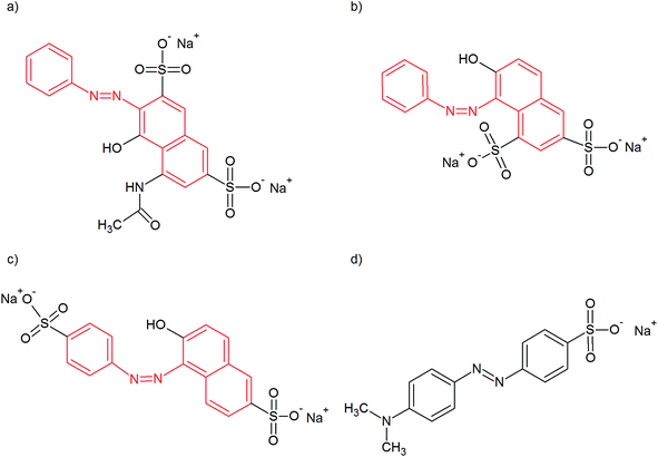 | ||
| Fig. 1 Azo dyes used as soft templates for the preparation of different PPy microstructures: (a) Acid Red 1, (b) Orange G, (c) Sunset Yellow FCF and (d) methyl orange for comparison. | ||
2. Experimental
2.1. Synthesis of PPy structures
Pyrrole, iron(II) chloride, Acid Red 1, Orange G, Sunset Yellow FCF, methyl orange (Sigma-Aldrich), and iron(III) chloride hexahydrate and hydrochloric acid (Penta) were used as received without any modifications. The chemical structures of the azo dyes with a naphthylphenyldiazene skeleton used are displayed in Fig. 1.The concentrations of the dyes used in the reactions followed the ascending sequence: 0.5, 2.5, 5, 10, 20, and 50 mM. An equimolar mole ratio of monomer to oxidant was kept. In a typical synthesis, 10 mmol (1.63 g) of iron(III) chloride hexahydrate was dissolved in 200 ml of a 5 mM solution of azo dye in deionized water. The solution was kept at 5 °C using a thermostat, and then 700 μl of pyrrole monomer was added dropwise in the first two hours of synthesis. Thus, the molar concentrations of the reactants were 50 mM for the iron(III) chloride hexahydrate and 50 mM for the pyrrole.
The course of synthesis and material purification was universal. During the synthesis (24 h), the mixture was stirred at a constant speed. The samples were purified by Soxhlet extraction using acetone for several days until the extraction reagent remained colourless. Then the obtained powder was dried at 40 °C in a vacuum dryer.
For comparison, the globular form of PPy (PPy-G) was also prepared without the presence of any azo dye from pyrrole (1 mM) and iron(III) chloride (1 mM) oxidant in an aqueous environment only. Iron(III) chloride was added dropwise into the aqueous pyrrole solution at 5 °C for 24 h with gentle stirring. Also for comparison, standard nanotubular PPy was prepared in the presence of MO as described earlier.21
The PPy synthesised using the recipes described above was (according to previous experiments25) considered as a polycation with the chloride and azo dye anions acting as the dopants. The former anion results from the oxidant – iron(III) chloride hexahydrate – and the latter result from azo dyes.
2.2. Preparation of binary systems
In order to systematically investigate the role of structure-guiding agents in the process of micro-structure synthesis, it was necessary to simulate their formation during the various stages of the reaction. So, the interaction of all three of the azo dyes (AR, OG and SY) in binary systems with four chemicals appearing in some stage of pyrrole polymerization – iron(III) chloride hexahydrate (oxidant), iron(II) chloride (the reduced form of the oxidant produced during the polymerization), hydrochloric acid (it is known that polymerization is connected with the production of protons and hence with the increasing acidity of the mixture) and pyrrole (monomer) – was studied. The samples were prepared by mixing the azo dyes and the relevant chemical at a mole ratio close to the situation in the polymerization reaction.2.3. Sample characterization
Optical microscopy (Nikon Eclipse LV100D with a digital camera, SONY DFW-SX910) in tandem with image analysis (software NIS-Elements AR 3.20) was used to observe the structure-guiding agents in the binary systems. Although optical microscopy is limited by the dimensions of observable objects, it proved to be a useful tool for in situ observation of the supramolecular structures in the systems containing MO.21 Moreover, the dyes in aqueous solution were studied in terms of the surface tension by the Du Noüy ring method (TD1 LAUDA). Measurements were carried out at 7 °C, which is the temperature approximately corresponding to the temperature used in the pyrrole polymerization.The morphology of the prepared microstructures was observed by scanning electron microscopy (SEM) using a MIRA 3 LMH (Tescan Company) microscope with Schottky-type cathode at an accelerating voltage of 3 kV. Elemental analysis was performed by energy dispersive X-ray microscopy (EDX) using a Quantax 200 analyzer with a XFlash 6|10 detector (Bruker Company) with a resolution of 129 eV and a 15 kV accelerating voltage, respectively.
The Fourier-transform infrared (FTIR) spectra of powdered samples dispersed in potassium bromide pellets were measured using a Thermo Nicolet NEXUS 870 FTIR Spectrometer with a DTGS TEC detector in the 400–4000 cm−1 wavenumber region. Raman spectra were recorded with a Renishaw InVia Reflex Raman microspectrometer using a near-infrared diode 785 nm laser excitation line. A research-grade Leica DM LM microscope was used to focus the laser beam. The scattered light was analysed with a spectrograph using a holographic grating with 1200 lines mm−1. The Peltier-cooled CCD detector (576 × 384 pixels) registered the dispersed light.
The powders of synthesized PPy were compressed at 540 MPa to form pellets of 13 mm in diameter and 0.5–1 mm in thickness. Their electrical conductivity was then measured by the four-point van der Pauw (VDP) method. The experimental set-up consisted of a Keithley 220 programmable current source, a Keithley 2010 multimeter as a voltmeter, and a Keithley 705 scanner equipped with a Keithley 7052 matrix card.
3. Results and discussion
3.1. Overview of the synthesized samples
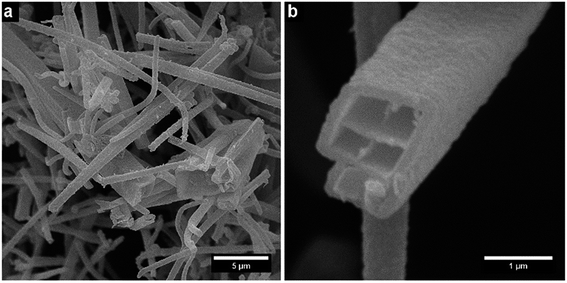
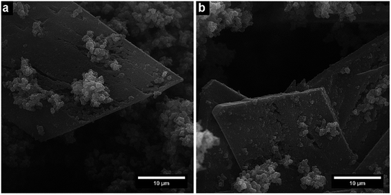
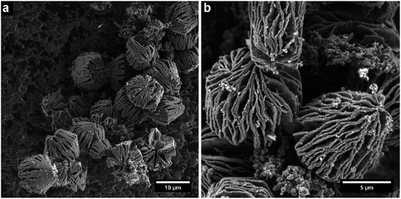
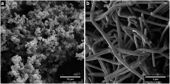
The resulting nano- and microstructures are displayed in the SEM images (Fig. 2–5). In principle, these forms appear: (1) rectangular nanotubes or nanorods of PPy-AR with cross-section dimensions ranging from tens of nanometres to units of micrometres and up to hundreds of micrometres in length (Fig. 2), and some of them possess multichamber cavities; (2) several micrometre large plates (Fig. 3) of PPy-OG combined with a globular structure; (3) several micrometre large barrel-like formations of PPy-SY (Fig. 4), some of these samples are mixtures of barrel-like formations, nanorods and globular structures; (4) finally, structures prepared for comparison – globular structures of PPy-G (Fig. 5a) and circular nanotubes of PPy-MO (Fig. 5b). The simplified sketches in Fig. 6 show all of structures present in the synthesized samples. The images obtained by SEM therefore reveal an interesting influence of the azo dyes used on the final geometry of the nano- and microstructures; the difference is particularly evident when comparing the structures shown in Fig. 2–4 with the structures shown in Fig. 5, where PPy-G and well-known PPy-MO are presented.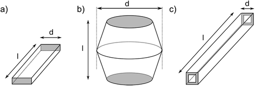 | ||
| Fig. 6 The supramolecular structures that appear in the samples: (a) plates, (b) barrel-like formations, and (c) rectangular nanotubes; their dimensions (d – diameter and l – length) are summarized in Table 1. | ||
Rectangular-shaped structures of PPy-AR were already observed in the past by Yan et al.13 (although at different synthesis conditions and at very high AR concentrations), but the plates of PPy-OG or barrel-like structures of PPy-SY are found, to the best of our knowledge, for the first time. As structures other than common nanotubes such as wires or rods are rather uncommon in the case of PPy, the influence of naphthylphenyldiazenes is worthy of further investigation and discussion.
Table 1 summarizes the basic properties (shape, electrical conductivity and approximate size) of all of the synthesized samples. Moreover, it also contains basic information about the standard PPy-G and PPy-MO references synthesized either without azo dye or using MO, respectively.21 At first glance, the values of conductivity of PPy-AR, PPy-SY and PPy-OG are moderate (in the order of units of S cm−1) and comparable to the conductivity of PPy-G (5.2 S cm−1) rather than to the value of conductivity of PPy-MO (48.7 S cm−1).
| Concentration of azo dye (mM) | Morphology | Conductivity (S cm−1) | Dimensionsa (nm) |
|---|---|---|---|
| a Diameter d in 1-D, size in 3-D.b From ref. 21. | |||
| No dye | |||
| n/a | Globular | 5.2 | n/a |
![[thin space (1/6-em)]](https://www.rsc.org/images/entities/char_2009.gif) |
|||
| Methyl Orange (reference) | |||
| 2.5 | 1-D | 48.7 | 190–310b |
![[thin space (1/6-em)]](https://www.rsc.org/images/entities/char_2009.gif) |
|||
| Acid Red 1 | |||
| 0.5 | Globular | — | n/a |
| 2.5 | 1-D | 2.3 | 630 ± 180 |
| 5 | 1-D | 2.7 | 630 ± 220 |
| 10 | 1-D | 1.5 | 580 ± 160 |
| 25 | 1-D | 0.2 | 820 ± 270 |
![[thin space (1/6-em)]](https://www.rsc.org/images/entities/char_2009.gif) |
|||
| Orange G | |||
| 0.5 | Globular | 8.4 | n/a |
| 2.5 | Globular | 9.7 | n/a |
| 5 | 3-D | 10.9 | 8700–26![[thin space (1/6-em)]](https://www.rsc.org/images/entities/char_2009.gif) 000 000 |
![[thin space (1/6-em)]](https://www.rsc.org/images/entities/char_2009.gif) |
|||
| Sunset Yellow FCF | |||
| 0.5 | Globular | — | n/a |
| 2.5 | Globular | — | n/a |
| 5 | 3-D | 3 | 6900–11![[thin space (1/6-em)]](https://www.rsc.org/images/entities/char_2009.gif) 600 600 |
| 10 | 1-D/3-D | 0.8 | 270–860/8800–10![[thin space (1/6-em)]](https://www.rsc.org/images/entities/char_2009.gif) 900 900 |
| 20 | 3-D | 12.7 | n/a |
| 25 | 3-D | 2.6 | n/a |
| 50 | 3-D | 8.3 | n/a |
The descriptions of the morphologies (Fig. 2–4) could be based on comparisons of similar microstructures of other conducting polymers. A plethora of papers are devoted to nanotubular polyaniline (PANI) or polythiophene (PEDOT), but only a few papers present their 3-D microstructures.34 Some of them are oriented toward the supramolecular structures of oligoanilines. Wang et al. published two papers devoted to oligoaniline microstructures.35,36 He presumed that oligoanilines are formed into highly organized structures which subsequently serve as seeds for the growth of polyaniline 3-D structures. Using this approach, Zhao et al.37 found highly ordered polyaniline microstructures of extraordinary beauty. On the other hand, 3-D structures of PPy are mostly known as a result of hard-template synthesis, but only a few of them result from soft-template synthesis, e.g. Santino et al.38 prepared PPy 3-D nanobrushes by low-temperature vapour-phase synthesis.
Thus, the typical morphology of PPy synthesized in the presence of a structure-guiding agent (e.g. surfactants or azo dyes) is mostly of 1-D shape,39 hence the development of structures other than 1-D structures is surprising. According to one of the generally accepted theories, the final shape of the PPy supramolecular structure is determined by the initial shape of the soft-template which is developed from the structure-guiding agent in aqueous solution. Moreover, it seems that development of the soft-template is connected with the transition of the azo dye salt into an azo dye acid as reported in recent work.24 Therefore, in order to reveal the possible mechanism behind this 3-D growth, we first have to study the behaviour of naphthylphenyldiazenes alone in aqueous solution.
3.2. Study of dye solutions and template formation
The investigated azo dyes (Fig. 1; SY, AR and OG) are composed of a similar hydrophobic naphthylphenyldiazene skeleton and they differ in the type and position of functional groups. They possess at least two hydrophilic sulfonic groups attached at different positions on the naphthylphenyldiazene skeleton. The existence of distinct hydrophobic and hydrophilic parts together with the possibility of hydrogen bond creation determines the shape of their self-assemblies in aqueous media, which are stacked together due to both π–π and hydrophobic interactions.37 Ionic bonds between the anion of the sulfonic group and the PPy polycation may also play some role during the polymerization of pyrrole.Unfortunately, there is a lack of specific information about the behaviour of the azo dyes AR, OG and SY in aqueous solution. Taking into account the variability of particular concentration ranges and the degree of freedom of how dye molecules can be mutually oriented,37 the shape of their self-assemblies is almost unpredictable. Some insight into the issue of self-assembly of naphthylphenyldiazene has been given by Horowitz et al.40 They investigated the behaviour of SY in aqueous solutions at different concentrations and found that SY behaves as chromonic liquid crystals whose molecules are stacked by π–π interactions and they undergo a phase transition to a separate ordered phase at high concentrations.
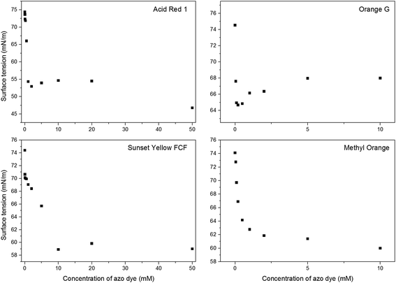
We have employed two tools in order to study aqueous solutions of the naphthylphenyldiazene dyes: (1) optical microscopy, which gives sufficient information about the soft-template structure at high azo dye concentrations; (2) measurement of the surface tension which covers a whole concentration range and reveals important transitions in azo dye solutions.
Azo dye–hydrochloric acid. Interaction of azo dye with hydrochloric acid simulates increasing the acidity of the native liquor during the polymerization process. According to the literature,21,31 increasing the acidity of the reaction mixture prevents hydration of β-azo-nitrogen and, consequently, the azo dye molecules escape from the bulk of the solution in the form of supramolecular structures. Moreover, the transition of methyl orange salt into methyl orange acid in an acidic environment is reported in recent work24 as one of the reasons for template formation. None of these phenomena were observed in the case of SY, AR or OG. This means, that the acidity of the reaction solution plays only a minor role in the synthesis of PPy structures.
Azo dye–iron(III) chloride. In the investigated systems, oblong template structures were found in the AR–iron(III) chloride system (Fig. 7a); these structures (40–60 μm long and 1–2 μm wide) appeared only for high concentrations of AR and only after longer periods of time (24 h). Similar structures were created in the OG–iron(III) chloride system (Fig. 7d). The remaining system, i.e. SY–iron(III) chloride, did not form any templates that were observable by optical microscopy.
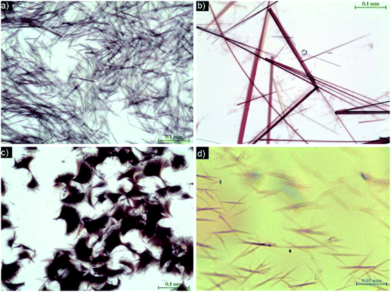 | ||
| Fig. 7 Binary systems of AR with: (a) iron(III) chloride, (b) iron(II) chloride, and (c) iron(II) chloride (higher concentration); and OG with (d) iron(III) chloride. | ||
The molecules of azo dyes can be influenced by iron(III) chloride in two ways: firstly, Fe3+ ions easily create complexes preferably with oxygen-containing ligand centres in azo dye molecules and, secondly, addition of iron(III) chloride to the solution will cause an increase in its acidity.13 As shown above, the acidity of the system plays only a minor role.
Azo dye–iron(II) chloride. Iron(II) chloride is generated as a product of the reduction of iron(III) chloride during the polymerization process. Of the studied systems, AR–iron(II) chloride yielded large objects up to 600 μm long and 1–10 μm wide.
In the azo dye–iron(II) chloride system the situation is somewhat different than that in the previous case: Fe2+ ions create complexes preferably with nitrogen-containing ligand centres of azo dye molecules and the acidity of the Fe2+ cation in the water environment is lower compared with that of the Fe3+ cation.
3.3. Elemental analysis using EDX
Elemental composition is always depicted as a ratio of element’s atoms to the number of pyrrole rings. In order to calculate the number of pyrrole rings, nitrogen originating from the azo dye has to be subtracted from the total nitrogen content according to a procedure introduced by Yang et al.12Determination of the elemental composition has revealed that azo dye AR remains in the bulk of PPy-AR (similar to MO in PPy-MO) despite the intensity of extraction,25 i.e. the amount of remnant AR molecules in PPy samples increases together with an increasing concentration of azo dye in the polymerization solution (up to an equimolar AR![[thin space (1/6-em)]](https://www.rsc.org/images/entities/char_2009.gif) :
:![[thin space (1/6-em)]](https://www.rsc.org/images/entities/char_2009.gif) pyrrole unit ratio). This means that the composite of PPy-AR is created at high AR concentrations, which usually has a negative influence on charge transport in supramolecular PPy, e.g. it decreased the conductivity of the samples (Table 1). EDX indicated the presence of such a composite by a high sulfur content in the samples (Fig. 9), as the only source of sulfur is the AR molecules.25 It is reasonable to assume that most of the remaining AR molecules are held in cavities of the nanotubes.13 On the other hand, PPy synthesized in the presence of SY contained a relatively steady concentration of sulfur in all of the samples regardless of its initial concentration in the polymerization mixture, which means that only a limited amount of SY molecules were held by PPy-SY. One of the reasons could be a lack of suitable cavities which are able to hold remnants of azo dye in this structure (see Fig. 4).
pyrrole unit ratio). This means that the composite of PPy-AR is created at high AR concentrations, which usually has a negative influence on charge transport in supramolecular PPy, e.g. it decreased the conductivity of the samples (Table 1). EDX indicated the presence of such a composite by a high sulfur content in the samples (Fig. 9), as the only source of sulfur is the AR molecules.25 It is reasonable to assume that most of the remaining AR molecules are held in cavities of the nanotubes.13 On the other hand, PPy synthesized in the presence of SY contained a relatively steady concentration of sulfur in all of the samples regardless of its initial concentration in the polymerization mixture, which means that only a limited amount of SY molecules were held by PPy-SY. One of the reasons could be a lack of suitable cavities which are able to hold remnants of azo dye in this structure (see Fig. 4).
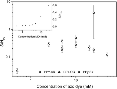 | ||
| Fig. 9 Content of sulfur in PPy-AR, PPy-OG and PPy-SY expressed as a ratio of the amount of sulfur to nitrogen in the pyrrole rings. Inset contains the same ratio for PPy-MO;25 error bars were removed for better orientation in the graph. | ||
The content of chlorine (Fig. 10) is the second important parameter of supramolecular PPy which can be obtained by EDX measurement. Chlorine is usually incorporated in the material as chloride ions acting as counter-ions bonded to backbone polycations, or it can be a sign of iron(III) chloride or iron(II) chloride remnants. Chloride ions usually indicate the degree of protonation/deprotonation.1 In the case of the PPy samples synthesized in the presence of both AR and SY, the content of chlorine quickly reached zero with an increasing azo dye concentration. Hence, for AR and SY the chlorine counter anions in PPy were replaced with anions of the respective azo-dyes. Moreover, there is no reason to believe that the chlorine was part of the remaining iron(III) chloride or iron(II) chloride molecules although a small amount of iron was found in the EDX spectra (up to 2 at%) of PPy-AR.
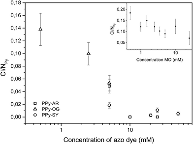 | ||
| Fig. 10 Content of chlorine in PPy-AR, PPy-OG and PPy-SY expressed as a ratio of the amount of chlorine to nitrogen in the pyrrole rings. Inset contains the same ratio for PPy-MO. | ||
3.4. Measurement of conductivity
The conductivity of novel PPy structures is a crucial parameter for their future application. Despite the highly-ordered shapes of PPy-AR, PPy-OG and PPy-SY, the electrical conductivity of these polymers is moderate, in the order of units of S cm−1 (Table 1). Such a value is comparable to that of PPy-G. We can discuss possible reasons why our samples do not exhibit conductivity similar to that of PPy-MO or higher. The first one could be the presence of low conducting residues, e.g. PPy-OG contains a high amount of unstructured globular PPy, and PPy-AR suffers from a higher content of AR remnants. These would reduce the overall conductivity by mixing with the (hypothetically) well-conducting structured PPy. Another reason, as shown by Long et al.,2 could be high contact resistance between individual supramolecular structures which can superimpose the intrinsic low resistance of highly ordered polymer chains of structures. When we consider the sizes and complex shapes of PPy-SY, PPy-OG and PPy-AR in comparison with those of PPy-MO, we should presume this second reason to be the more important one.Besides the value of conductivity, temporal stability is another important parameter for their use. Fig. 11 depicts the time dependence of the conductivity of the polypyrrole samples. It is apparent that, in principle, all of the samples follow the same generalized “aging curve”, regardless of the type of azo dye (or even its presence). When comparing the half-life time t0.5 (defined as the aging time required for the conductivity to be halved from the initial value σ0, σ(t0.5) = 0.5σ0) of all of the samples (excluding PPy-OG because of the high PPy-G content), it is clear that PPy synthesized in naphthylphenyldiazenes possesses stability comparable to that of PPy-G (t0.5 is approx. 70–80 days). Thus, no stabilizing effect of the azo dye was observed unlike in the case of PPy prepared in the presence of methyl orange (t0.5 is approx. 400–450 days) where the stability was greatly enhanced with an increasing MO concentration.41 Both its moderate conductivity and its stability probably reflect the highly-disordered state of PPy in all of the samples typical for PPy-G and contrary to PPy-MO which contains well-ordered highly conducting regions.42
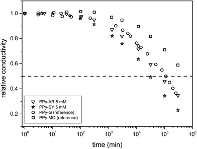 | ||
| Fig. 11 Measurement of the time dependence of the conductivity of the PPy samples. The legend displays the initial values of conductivity. | ||
3.5. FTIR and Raman spectroscopy
The infrared spectrum of standard PPy-G prepared without any dye (Fig. 12) exhibits the previously described main bands.43–45 The weak band at 1700 cm−1 corresponds to the presence of a carbonyl group attributed to the nucleophilic attack of water during the preparation.45 We detect the maximum situated at 1536 cm−1 (C–C stretching vibrations in the pyrrole ring), the broad band with maxima at 1472 and 1445 cm−1 (C–N stretching vibration in the pyrrole rings), and the maximum at 1295 cm−1 (C–H or C–N in-plane deformation modes), and the broad band with the maximum situated at 1165 cm−1 (the breathing vibrations of the pyrrole rings). We observe the peak at 1092 cm−1 (N–H+ deformation) and a sharp band at 1037 cm−1 (C–H and N–H in-plane deformation vibrations). Bands situated at 964 cm−1 (C–C out-of-plane ring-deformation), at 895 cm−1 (C–H out-of-plane deformation of the ring) and at 782 cm−1 (C–H out-of-plane ring deformation) are also present in the spectrum.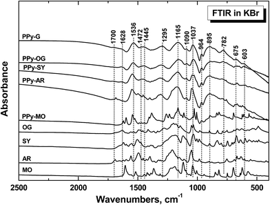 | ||
| Fig. 12 FTIR spectra of polypyrrole prepared without any dye (PPy-G) and in the presence of 5 mM OG, 5 mM SY, 5 mM AR, and 3.5 mM MO. The spectra of corresponding dyes are shown for comparison. | ||
The infrared spectra of nanostructured PPy prepared in the presence of azo dyes (Fig. 12) only slightly differ from the spectrum of globular PPy. We detect some small peaks of dyes in the spectra. Very small peaks of OG, few higher peaks and the shift of the peaks at 1536 and 1295 and 1037 cm−1 to higher wavenumbers in case of SY and AR are observed. For PPy prepared in the presence of methyl orange we observe practically the spectrum of the dye, which corresponds to the acidic form of methyl orange.21,23,24 The shifts of the main bands of PPy correspond most probably to overlapping with the peaks of the corresponding dyes. The shape of the spectra, especially in the region above 1600 cm−1, corresponds to the decreasing conductivity in the order PPy-G > PPy-OG > PPy-SY > PPy-AR,1 except for PPy-MO, which has the highest conductivity and highest peaks of MO in the spectrum. Raman scattering is a more convenient spectroscopic method to study the presence of polarons and bipolarons in the PPy structure.
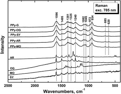
The Raman spectrum of standard PPy-G prepared without any dye (Fig. 13) exhibits the previously described main bands.1,23,24,46–48 We observe the band at 1596 cm−1 (C![[double bond, length as m-dash]](https://www.rsc.org/images/entities/char_e001.gif) C stretching vibrations of the PPy backbone), two bands of ring-stretching vibrations at 1381 and 1326 cm−1 (the intensity of the latter increases after deprotonation), the band at 1240 cm−1 (antisymmetric C–H deformation vibrations) and the double peak with local maxima at 1082 and 1045 cm−1 (C–H out-of-plane deformation vibrations, the second one becomes sharper in the case of deprotonation) in the spectrum. The band at 972 cm−1 (the ring-deformation vibrations of neutral polypyrrole units) and the sharp peak at 934 cm−1 (the ring-deformation vibrations in dication–bipolaron units) are well-detected in the spectrum.1,43,46–48
C stretching vibrations of the PPy backbone), two bands of ring-stretching vibrations at 1381 and 1326 cm−1 (the intensity of the latter increases after deprotonation), the band at 1240 cm−1 (antisymmetric C–H deformation vibrations) and the double peak with local maxima at 1082 and 1045 cm−1 (C–H out-of-plane deformation vibrations, the second one becomes sharper in the case of deprotonation) in the spectrum. The band at 972 cm−1 (the ring-deformation vibrations of neutral polypyrrole units) and the sharp peak at 934 cm−1 (the ring-deformation vibrations in dication–bipolaron units) are well-detected in the spectrum.1,43,46–48
In the Raman spectra of PPy prepared in the presence of azo dyes (Fig. 13) we observe the same bands practically at the same positions as in the spectrum of PPy-G. This means that both forms have identical molecular structure and may differ only in the organization of polymer chains. The energy of the laser excitation line 785 nm is in resonance with the energy of the delocalized polarons and bipolarons in PPy and the spectrum obtained with the laser excitation at 785 nm corresponds to the surface of the structured PPy. We can conclude that dyes are present mostly inside of them. From the ratio of the intensities of the peaks at 1082 and 1045 cm−1 we can conclude that the doping level of the surface of the samples decreases from PPy-OG > PPy-SY > PPy-AR > PPy-MO > PPy-G. As the highest conductivity exhibit the samples of nanotubular PPy-MO and PPy-G, we suppose that the charge transport proceeds preferably inside the structures where PPy is in contact with dyes.
4. Conclusions
The azo dyes Acid Red 1, Orange G and Sunset Yellow FCF, with naphthylphenyldiazene skeletons, were used as soft-templates for the preparation of PPy in aqueous solution. The resulting “conventional” 1-D and “novel” 3-D supramolecular structures were observed by SEM and their properties (chemical composition, structure and electrical conductivity) were compared to those of standard globular PPy and also to those of the well-known nanotubular PPy prepared in the presence of methyl orange. A deeper insight was also made into the nature of soft-template formation.Based on measurements of the dependence of surface tension on azo dye concentration, it can be concluded that supramolecular structures of neat morphology are formed only near the point of abrupt change of surface tension (which is usually referred to as the “critical micelle concentration”). Neither lower nor higher concentrations lead to neater morphology with enhanced properties. Lower concentrations of azo dyes result in a mixture of globular PPy and its supramolecular structures, and higher concentrations usually lead to the formation of a composite of azo dye and PPy.
The shape of the PPy supramolecular structures can be controlled using azo dyes with different chemical structures and, besides the nanotubes, novel PPy supramolecular structures can be expected when using structure-guiding agents from a large group of the azo dyes that have not been tested so far. However, it is still a challenge to predict the final shape of the PPy supramolecular structure when the positions of the functional hydrophilic and hydrophobic groups of the azo dye are slightly changed compared to those azo dyes whose structure-guiding behaviour is well known. Easier prediction is expected in the case of azo dyes creating solid crystals in aqueous solutions which can be observed by e.g. optical microscopy, but such prediction is very difficult in the case of the azo dyes creating liquid crystals.
Unfortunately, none of the as-presented supramolecular structures of PPy possess better conductivity and long-term stability than nanotubes of PPy prepared in the presence of methyl orange.
However, this work illustrates a great potential which is still hidden in the polymerization of PPy using structure-guiding agents from the group of azo dyes. This area is still far from being investigated (and much less understood or interpreted). We can conclude that at least the morphology of synthesized PPy is an easily and reproducibly tunable parameter. Even in the small set of azo dyes presented in this paper (MO, AR, OG and SY), rectangular nanotubes, rectangular nanorods, flat plates, barrel-like formations, circular nanotubes or globules were synthesised. Such results can be considered as a contribution to the bottom-up approach of modifying PPy morphology.
Conflicts of interest
There are no conflicts to declare.Acknowledgements
The authors thank the Czech Science Foundation (17-04109S, 17-13427S) for financial support. This research was also sponsored by the NATO Public Diplomacy Division in the framework of “Science for Peace” (984597).References
- J. Stejskal, M. Trchová, P. Bober, Z. Morávková, D. Kopecký, M. Vrňata, J. Prokeš, M. Varga and E. Watzlová, RSC Adv., 2016, 6, 88382–88391 RSC.
- Y. Z. Long, M. M. Li, C. Z. Gu, M. X. Wan, J. L. Duvail, Z. W. Liu and Z. Y. Fan, Prog. Polym. Sci., 2011, 36, 1415–1442 CrossRef CAS.
- Q. L. Xu, G. W. Meng, F. M. Han, X. L. Zhao, M. G. Kong and X. G. Zhu, Mater. Lett., 2009, 63, 1431–1434 CrossRef CAS.
- S. Goel, N. A. Mazumdar and A. Gupta, Polym. Adv. Technol., 2010, 21, 205–210 CrossRef CAS.
- N. R. Chiou and A. J. Epstein, Adv. Mater., 2005, 17, 1679–1683 CrossRef CAS.
- H. Liu, X. B. Hu, J. Y. Wang and R. I. Boughton, Macromolecules, 2002, 35, 9414–9419 CrossRef CAS.
- M. R. Karim, C. J. Lee, A. M. S. Chowdhury, N. Nahar and M. S. Lee, Mater. Lett., 2007, 61, 1688–1692 CrossRef.
- J. Jang and H. Yoon, Chem. Commun., 2003, 720–721 RSC.
- T. S. Kang, S. W. Lee, J. Joo and J. Y. Lee, Synth. Met., 2005, 153, 61–64 CrossRef CAS.
- P. S. Thapa, D. J. Yu, J. P. Wicksted, J. A. Hadwiger, J. N. Barisci, R. H. Baughman and B. N. Flanders, Appl. Phys. Lett., 2009, 94, 033104 CrossRef.
- X. Q. Hu, Y. Lu and J. H. Liu, Macromol. Rapid Commun., 2004, 25, 1117–1120 CrossRef CAS.
- X. M. Yang, Z. X. Zhu, T. Y. Dai and Y. Lu, Macromol. Rapid Commun., 2005, 26, 1736–1740 CrossRef CAS.
- W. Yan and J. Han, Polymer, 2007, 48, 6782–6790 CrossRef CAS.
- J. T. Feng, W. Yan and L. Z. Zhang, Microchim. Acta, 2009, 166, 261–267 CrossRef CAS.
- S. M. Shang, X. M. Yang and X. M. Tao, Polymer, 2009, 50, 2815–2818 CrossRef CAS.
- J. J. Xu, J. C. Hu, B. G. Quan and Z. X. Wei, Macromol. Rapid Commun., 2009, 30, 936–940 CrossRef CAS PubMed.
- H. Y. Mi, X. G. Zhang, Y. L. Xu and F. Xiao, Appl. Surf. Sci., 2010, 256, 2284–2288 CrossRef CAS.
- M. Li, W. G. Li, J. Liu and J. S. Yao, J. Mater. Sci.: Mater. Electron., 2013, 24, 906–910 CrossRef CAS.
- X. M. Yang, L. A. Li and Y. Zhao, Synth. Met., 2010, 160, 1822–1825 CrossRef CAS.
- J. Upadhyay and A. Kumar, Mater. Sci. Eng., B, 2013, 178, 982–989 CrossRef CAS.
- J. Kopecká, D. Kopecký, M. Vrňata, P. Fitl, J. Stejskal, M. Trchová, P. Bober, Z. Moravková, J. Prokeš and I. Sapurina, RSC Adv., 2014, 4, 1551–1558 RSC.
- M. Joulazadeh and A. H. Navarchian, Synth. Met., 2015, 199, 37–44 CrossRef CAS.
- I. Sapurina, Y. Li, E. Alekseeva, P. Bober, M. Trchová, Z. Morávková and J. Stejskal, Polymer, 2017, 113, 247–258 CrossRef CAS.
- Y. Li, P. Bober, M. Trchová and J. Stejskal, J. Mater. Chem. C, 2017, 5, 4236–4245 RSC.
- D. Kopecký, M. Varga, J. Prokeš, M. Vrňata, M. Trchová, J. Kopecká and M. Václavík, Synth. Met., 2017, 230, 89–96 CrossRef.
- X. J. Jiang, T. Dai and Y. Lu, Iran. Polym. J., 2008, 17, 645–651 CAS.
- J. Ferreira, M. J. L. Santos, R. Matos, O. P. Ferreira, A. F. Rubira and E. M. Girotto, J. Electroanal. Chem., 2006, 591, 27–32 CrossRef CAS.
- M. Szymczyk, A. El-Shafei and H. S. Freeman, Dyes Pigm., 2007, 72, 8–15 CrossRef.
- M. Knížek and M. Musilová, Talanta, 1968, 15, 479–481 CrossRef.
- R. L. Reeves and S. A. Harkaway, J. Colloid Interface Sci., 1978, 64, 342–347 CrossRef CAS.
- T. Y. Dai and Y. Lu, Macromol. Rapid Commun., 2007, 28, 629–633 CrossRef CAS.
- K. L. Kendrick and W. R. Gilkerson, J. Solution Chem., 1987, 16, 257–267 CrossRef CAS.
- H. P. Frank, J. Colloid Sci., 1957, 12, 480–495 CrossRef CAS.
- Y. H. Cheng, C. W. Kung, L. Y. Chou, R. Vittal and K. C. Ho, Sens. Actuators, B, 2014, 192, 762–768 CrossRef CAS.
- Y. Wang, H. D. Tran, L. Liao, X. F. Duan and R. B. Kaner, J. Am. Chem. Soc., 2010, 132, 10365–10373 CrossRef CAS PubMed.
- Y. Wang, J. L. Liu, H. D. Tran, M. Mecklenburg, X. N. Guan, A. Z. Stieg, B. C. Regan, D. C. Martin and R. B. Kaner, J. Am. Chem. Soc., 2012, 134, 9251–9262 CrossRef CAS PubMed.
- Y. C. Zhao, J. Stejskal and J. X. Wang, Nanoscale, 2013, 5, 2620–2626 RSC.
- L. M. Santino, S. Acharya and J. M. D’Arcy, J. Mater. Chem. A, 2017, 5, 11772–11780 CAS.
- H. D. Tran, D. Li and R. B. Kaner, Adv. Mater., 2009, 21, 1487–1499 CrossRef CAS.
- V. R. Horowitz, L. A. Janowitz, A. L. Modic, P. A. Heiney and P. J. Collings, Phys. Rev. E: Stat., Nonlinear, Soft Matter Phys., 2005, 72, 041710 CrossRef PubMed.
- M. Varga, D. Kopecký, J. Kopecká, I. Křivka, J. Hanuš, A. Zhigunov, M. Trchová, M. Vrňata and J. Prokeš, Eur. Polym. J., 2017, 96, 176–189 CrossRef CAS.
- M. Varga, J. Kopecká, Z. Morávková, I. Křivka, M. Trchová, J. Stejskal and J. Prokeš, J. Polym. Sci., Part B: Polym. Phys., 2015, 53, 1147–1159 CrossRef CAS.
- G. Ćirić-Marjanović, S. Mentus, I. Pašti, N. Gavrilov, J. Krstić, J. Travas-Sejdic, L. T. Strover, J. Kopecká, Z. Morávková, M. Trchová and J. Stejskal, J. Phys. Chem. C, 2014, 118, 14770–14784 Search PubMed.
- N. V. Blinová, J. Stejskal, M. Trchová, J. Prokeš and M. Omastová, Eur. Polym. J., 2007, 43, 2331–2341 CrossRef.
- M. Omastová, M. Trchová, J. Kovářová and J. Stejskal, Synth. Met., 2003, 138, 447–455 CrossRef.
- K. Crowley and J. Cassidy, J. Electroanal. Chem., 2003, 547, 75–82 CrossRef CAS.
- Y. C. Liu, J. Electroanal. Chem., 2004, 571, 255–264 CrossRef CAS.
- S. Gupta, J. Raman Spectrosc., 2008, 39, 1343–1355 CrossRef CAS.
| This journal is © The Royal Society of Chemistry 2017 |

