 Open Access Article
Micro heat pipe device utilizing extended nanofluidics†
Chenxi Wang *a,
Yutaka Kazoe
 b,
Kyojiro Morikawa
 b,
Hisashi Shimizu
 b,
Yuriy Pihosh
 b,
Kazuma Mawatari
 b and
Takehiko Kitamori
 *b
*b
aState Key Laboratory of Welding and Joining, Harbin Institute of Technology, Harbin 150001, China. E-mail: wangchenxi@hit.edu.cn; Fax: +86-451-86416186; Tel: +86-451-86418359
bDepartment of Applied Chemistry, School of Engineering, The University of Tokyo, 7-3-1 Hongo, Bunkyo, Tokyo 113-8656, Japan. E-mail: kitamori@icl.t.u-tokyo.ac.jp; Fax: +81-3-5841-6039; Tel: +81-3-5841-7231
First published on 31st October 2017
Abstract
The next-generation cooling devices are gradually being scaled to smaller than the size of high-performance microchips to enable local heat removal from small hot spots. Realization of a micro/nanofluidic heat pipe device is a challenging task, as it requires high condensation efficiency in an ultra-small space and sufficient liquid transport without employing any wick. Herein, we demonstrate a two-phase loop micro heat pipe device based on unique liquid properties in extended nanospace (10–1000 nm) to meet the growing demands of the miniaturization of electronics and optoelectronics. The device, which contains a small volume of liquid (tens of nanoliter) and does not require a wick, can be conveniently embedded in the microchip. The capillary condensation of water on nanopillars was investigated. The experimental results showed a significant enhancement of the condensation rate on nanopillars for a faster vapor–liquid phase transition. In addition, a streaming potential measurement was performed to evaluate the liquid transport during operation of the micro heat pipe device. This method enables the measurement of water flow rates through extended nanochannels without requiring probe molecules. The micro heat pipe device was verified to work properly. Finally, the cooling performance of the micro heat pipe device was quantitatively estimated, and improvements were proposed to achieve highly efficient cooling.
1. Introduction
Recent advances in miniaturization have resulted in electronic components with a dramatically high increase in power density.1–4 Thermal management has been and will continue to be a critical issue for future high-performance microprocessors and microchips because a larger amount of heat is generated from increasing power densities.5 Compared to the thermal management at the system level, cooling at the chip level remains a major bottleneck to the reliability and performance of very large-scale integration (VLSI) circuits since small hot spots generate a local mass heat flux, leading to a highly non-uniform temperature gradient.6–9 For several decades, many efforts have been made to develop micro-cooling technologies that can efficiently remove the heat flux.10,11 Among these technologies, heat pipes that combine the principles of both thermal conductivity and the vapor–liquid phase transition appear to be a promising cooling techniques to manage the heat transfer of electronic devices, such as computers, laptops, telecommunication and satellite modules.12,13 However, conventional heat pipes combined with large electric fans are difficult to integrate into microchips. Micro-grooved heat pipes, one of the most commonly used micro heat pipes, are suitable for small semiconductor devices because they can be fabricated and integrated into the microchips through microelectromechanical (MEMS) technology.14,15 In most micro-grooved heat pipes, the liquid–vapor friction interactions originating from the countercurrent flow in the same groove can degrade the heat transfer performance. Consequently, two-phase loop micro heat pipe devices have emerged as a desirable solution since the liquid and vapor flow paths are separated to avoid the interfacial friction interactions.16,17 Although these two-phase loop devices can sustain a high heat flux, they generally require wicks for operation, which limits their ability to follow the trends of further device miniaturization. To obtain high heat transfer for high-performance wearable devices, it is desirable to embed micro heat pipes in the microchip using very small hydraulic diameters without requiring wicks.Recently, microfluidic spaces have been scaled down to sizes on the order of 10–1000 nm, which is a range known as an “extended nanospace” to distinguish it from a nanospace in the 1–10 nm range.18 Unique liquid properties in extended nanospaces have been reported, e.g., high viscosity, low dielectric constant, and high proton mobility.19–21 Based on these unique properties, a femtoliter-scale (fL = 10−15 L) immunoassay22 and femtoliter to attoliter-scale (aL = 10−18 L) chromatography23 platforms have been developed for innovative biomedical and chemical applications, respectively. An autonomous solar-light-driven micro fuel-cell device has also been realized.24 Hibara et al. found that the vapor pressure in extended nanopillars is lower than that on flat surfaces,25 suggesting that the capillary condensation of water can be more easily accomplished in extended nanospaces than in bulk spaces. Utilization of the unique properties of water in the extended nanofluidic space can create new possibilities for the development of micro heat pipe devices.
Herein, we propose a two-phase loop micro heat pipe device utilizing extended nanopillars and nanochannels. The device consist of micro/nanochannels that do not incorporate wicks. To address the condensation efficiency in extended nanospaces, the capillary condensation of water on nanopillars is investigated in this study. However, monitoring liquid transports in the extended nanochannels of the micro heat pipe is a tremendous challenge because nanoparticles or fluorescent dyes are not allowed into the liquid–vapor phase. To overcome this problem, we develop a streaming potential measurement to evaluate liquid transports during the operation of the micro heat pipe device. This method enables the measurement of water flow rates in extended nanochannels without requiring probe molecules. Thus, the cooling performance is quantitatively estimated, and improvements to this performance are discussed.
2. Principle
Fig. 1 illustrate the conceptual design of the micro heat pipe device utilizing extended nanopillars and nanochannels. The device focuses on local cooling of a hot spot (∼mm size) in a several-centimeter-sized VLSI chip. The two-phase loop micro heat pipe consists of a microchannel (for vapor transport) and extended nanochannels on two sides (for liquid transport). The microchannel connected to the two nanochannels is bridged by the extended nanopillars. At the initial stage, nanochannels on both sides are charged with water. When the water is locally heated from the hot spot (i.e., the evaporator), the generated vapor flows along the microchannel to the nanopillars (i.e., the condenser), allowing enhanced capillary condensation of water due to the unique liquid properties in extended nanospace. After water condensation occurs, the high Laplace pressure dominated by the surface tension in the side nanochannels can drive the condensation water back to the evaporator for re-evaporation. The liquid–vapor circulates in a closed-loop micro/nanospace, while evaporation and condensation occur simultaneously for heat absorption and dissipation, respectively. The capillary condensation efficiency and the liquid transport play two important roles in the cooling performance.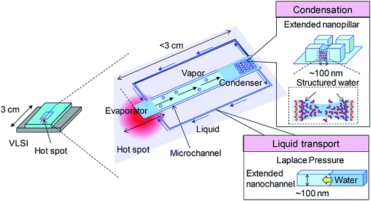 | ||
| Fig. 1 Conceptual design of the micro heat pipe device utilizing extended nanopillars and nanochannels. | ||
3. Experimental
3.1 Device design and fabrication
Extended nanopillars (pillar width = pillar interval) were fabricated on fused silica substrates (VIOSIL-SQ, Shinetsu Chemical, Japan) by electron beam lithography and plasma etching. The fabrication process of the nanopillars is similar to the nanochannel fabrication process described in the literature.26 The extended nanopillars with various intervals ranging from 150 nm to 2000 nm were successfully fabricated and were confirmed using scanning electron microscopy (SEM). The depth of all the nanopillars was 300 nm. An investigation of the capillary condensation of water on the nanopillars was performed.Fig. 2 shows the design and a photograph of the micro heat pipe device, which includes the vapor condensation and the condensation water circulation. On one fused silica substrate, a microchannel (with a 1000 μm width and a 3 μm depth) was fabricated to transport the vapor from an evaporator measuring 1 mm2. On another substrate, a two-dimensional extended nanopillar array (with a 250 nm interval and a 300 nm depth) was fabricated, which was proposed as a condenser to allow enhanced capillary condensation. Meanwhile, two sets of side extended nanochannels (with a 500 μm width and a 300 nm depth) that were connected to the nanopillars were fabricated to transport the condensation water. The two fused silica substrates were finally bonded using a low-temperature bonding process at 110 °C.27
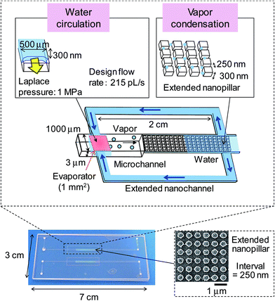 | ||
| Fig. 2 Design parameters and photograph of the micro heat pipe device. An inset SEM image shows the extended nanopillars with a 250 nm interval integrated in the device. | ||
During device operation, the capillary flow occurs spontaneously, and the flow rate depends on the balance between the Laplace pressure PL (driving force) and the pressure drop Pf (friction drag). From the Young–Laplace equation and the Hagen–Poiseuille law, the flow rate can be calculated as follows:28
 | (1) |
 | (2) |
3.2 Heat pipe device working system
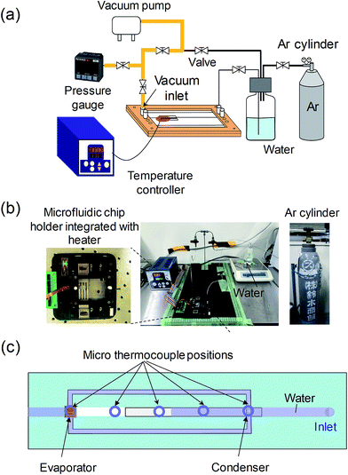
After the micro heat pipe device was fabricated, it was partially filled with deionized (DI) water. Prior to charging the device with water, non-condensable air in the device must be removed because the residual air may degrade the device performance. Therefore, the device should be evacuated to a low pressure. Fig. 3a and b illustrate a vacuum system including the gas lines that we developed to evacuate the residual air from the micro/nanochannels. The device was integrated with a stainless chip holder in which the gas/water inlets and outlets were sealed hermetically. The pressure of the vacuum background was ∼0.3 kPa before introducing water. The DI water was degassed initially and then was introduced into the designated micro/nanochannels using a controlled pressure of Ar gas. The working environment was maintained at room temperature (19 ± 1 °C). A specific temperature control stage (Citizen, Japan) was employed to accurately heat the device at the evaporator position (evaporator size: 1 × 1 mm2) over a range from 19 °C to 120 °C. Additionally, five sets of micro thermocouples (not shown in Fig. 3b) were attached to the device to measure the temperatures at various positions.3.3 Flow rate measurement system
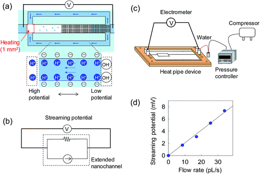
To verify the device working principle and to evaluate the cooling performance, the flow rates in the extended nanochannels were monitored by the streaming potential measurement. The detailed principle of the streaming potential/current measurement has been previously reported.29,30 Fig. 4a illustrates monitoring of the flow rate in the extended nanochannels while the heat pipe device was operating. For electrical measurements, Ag/AgCl electrodes (fabricated by coating Pt wires with Ag/AgCl paste) were inserted into the inlet and the outlet reservoirs of the microchannels. Each electrode was connected to an electrometer (Keithley 6514, Keithley Instruments, USA) using voltage measurement mode. The equivalent circuit is shown in Fig. 4b. The microchannel between the evaporator and the condenser is an electrical disconnection because of the vapor path. In the calibration test, the DI water flow was driven in the extended nanochannel by a pressure controller (Fig. 4c), and the streaming potential generated between Ag/AgCl electrodes was detected by the electrometer. The noise generated in the connected microchannels could be ignored. The calibration curve was constructed by plotting streaming potential against flow rate in the extended nanochannel (Fig. 4d).4. Results and discussion
4.1 Capillary condensation on nanopillars
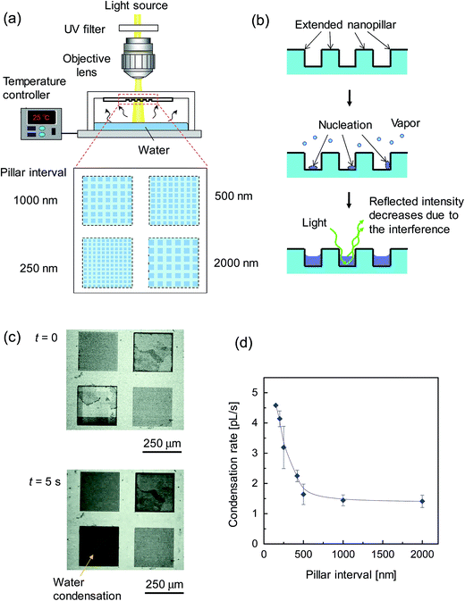
The capillary condensation of water on extended nanopillars was characterized. Four sets of nanopillar arrays with different intervals, e.g. 2000 nm, 1000 nm, 500 nm and 250 nm, were fabricated on a fused-silica glass substrate as a group. Fig. 5a shows the experimental setup. The substrate with the fabricated nanopillars was fully attached to a transparent glass cover, which maintained the DI water on a temperature control stage for evaporation without outside leakage. To avoid an undesirable heat effect during the measurement, an optical microscope (Nikon E400, Nikon, Japan) with a UV-filtered light source was employed to record the capillary condensation process using a charge-coupled device (CCD) camera. The experimental environment was maintained at room temperature (19 ± 1 °C).When the water was evaporated (the temperature was elevated to 35 °C at the stage), the generated vapor moved upward and condensation occurred on the four sets of nanopillars simultaneously. Fig. 5b illustrates the capillary condensation process, which consisted of the nucleation and filling of the nanopillar intervals. The reflected light intensity of the nanopillar region decreased during the condensation process due to the interference between the reflected lights. The CCD captured micrographs of the 250 nm nanopillars changing from light to dark during capillary condensation, as shown in Fig. 5c (see the real-time movie in the ESI†). Imaging processing software was employed to quantitatively analyze the condensation region. In our experiments, the condensation water always filled the small-sized nanopillars before filling the large-sized ones. The capillary condensation rate was calculated by the ratio of the condensation water volume to the condensation time.
Fig. 5d shows the size dependency of the capillary condensation rate of water on nanopillars. The condensation rate increased significantly with decreasing nanospace size. In particular, the condensation rate on 150 nm nanopillars was much higher (>3 times higher) than the rate on 1000 nm nanopillars. Due to the effect of the surface-to-volume ratio, the total surface area of small-sized nanopillars is larger than that of large-sized ones. Therefore, water molecules have more opportunities for nucleation and for bridging easily during the water filling process into the intervals. In addition, in this extended nanospace, the properties of uniquely structured water with high proton mobility and high viscosity were reported in our previous study.19,21 This enhanced condensation in an extended nanospace is considered to facilitate a faster vapor–liquid phase transition.
4.2 Verification of the device working principle
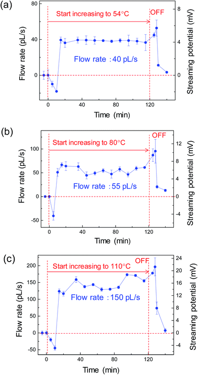
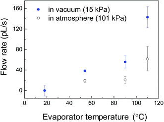
The flow rate of the condensation water in the extended nanochannels (returning to the evaporator) was monitored to verify proper operation of the heat pipe. During the device operation, the liquid/vapor flow was autonomous in all micro/nanochannels without applying any external pressure. The evaporator was heated and maintained at 54 °C, 80 °C and 110 °C for 120 min at each temperature. Each elevated temperature at the evaporator was calibrated using the micro thermocouple. Fig. 6 shows the water flow rates in the extended nanochannel as monitored by the streaming potential measurements. At the initial stage, all the water flow occurred in a reverse direction due to the evaporation and resistance–capacitance (RC)-circuit delay. As shown in Fig. 6a, the evaporator was maintained at 54 °C for 120 min, and the flow rate was 40 pL s−1. During the operation, the accumulated water volume along the extended nanochannels was ∼248 nL. The design water volume in the two extended nanochannels was 15 nL. The results demonstrate that more than 16 cycles of water circulation occurred in 120 min, confirming that the micro heat pipe device operated properly. Furthermore, we tested this device could work properly for a longer duration (e.g., 12 h or more) with no problem.Fig. 7 shows the water flow rate in the extended nanochannel as a function of evaporator temperature maintained during operation of the heat-pipe device. In general, the water flow rates along the side extended nanochannels increased as the evaporator temperature increased. When the evaporator was heated and maintained at a maximum temperature of 110 °C for 120 min, the flow rate increased to 150 pL s−1, and more than 56 cycles of the water circulation occurred while the device was operating. For heating at a higher temperature (e.g., 115 °C), the measured streaming potentials decreased substantially to ∼0 mV due to “dry out” at the evaporator.
4.3 Cooling performance and its improvement
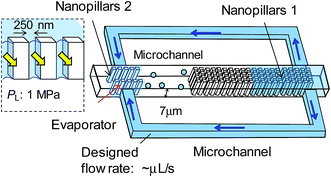
The cooling performance of the micro heat pipe is roughly estimated by calculating the liquid flow rate Q × liquid latent heat Lm. The maximum flow rate of 150 pL s−1 corresponds to a cooling performance of 3.4 × 10⁻⁴ W cm−2, which is equivalent to 70% of the design performance (4.9 × 10⁻⁴ W cm−2 for the design flow rate of 215 pL s−1). The lower cooling performance than the design value may be due to the high vacuum pressure. Although the vacuum system could evacuate the micro/nanochannel to a gas pressure of ∼0.3 kPa, the actual gas pressure increased to ∼15 kPa before water was introduced. For comparison, the flow rates when the device was operating at atmospheric pressure (∼101 kPa) were measured, as shown in Fig. 6. The result implies that the cooling performance might be improved using a high-vacuum system.The low cooling performance is primarily attributed to the very small liquid transport in our current device. Fig. 8 shows a prospective design of a micro heat pipe device for a higher heat transportation. Two sets of side microchannels (with a 7 μm depth) are proposed instead of the extended nanochannels (with a 300 nm depth) for liquid mass transport (∼2.5 μL s−1). Based on the effect of the surface-to-volume ratio on capillary condensation, high aspect-ratio nanopillars (e.g., nanopillar 1 with a 250 nm interval and a 7 μm depth) are integrated into the device for enhanced capillary condensation. Moreover, an additional set of the extended nanopillar array (e.g., nanopillar 2 with a 250 nm interval and a 7 μm depth) is selectively proposed at the evaporator to mitigate “dry out” for higher operating temperatures and to provide a high Laplace pressure (PL = 1 MPa) for driving liquid. The fabrication of these high aspect-ratio nanopillars on a fused silica substrate is challenging, but a similar fabrication process has been previously described.31 The design cooling performance of the prospective device is 2.5 W cm−2. Furthermore, tens of these micro heat pipe devices are expected to be integrated on a chip for a highly efficient cooling performance.
5. Conclusions
We demonstrated for the first time a two-phase loop micro heat pipe device utilizing extended nanopillars and nanochannels. In contrast to the conventional two-phase loop micro heat pipe device that requires large microchannel and additional wicks, our micro heat pipe device consists of small micro/nanochannels (containing ∼101 nL liquid) and does not require a wick. The capillary condensation of water on nanopillars was investigated in this study. The experimental results showed a significant enhancement of the condensation rate on nanopillars for a faster vapor–liquid phase transition. In addition, the streaming potential measurement was performed to evaluate liquid transport during operation of the micro heat pipe device, without involving probe molecules. The micro heat pipe device was verified to work properly. Although the cooling performance of the current device was not sufficient, a prospective design of a micro heat pipe device was proposed to realize high-performance cooling. We believe that our micro heat pipe has great potential in thermal control solutions at the chip level for miniaturization of next-generation electronics and optoelectronics.Conflicts of interest
There are no conflicts to declare.Acknowledgements
This work was financially supported by the Core Research for Evolutional Science and Technology (CREST) of the Science and Technology Corporation (JST) of Japan. The authors acknowledge the financial support from the National Natural Science Foundation of China (Grant No. 51505106), the China Postdoctoral Science Foundation (Grant No. 2017M610207) and the Heilongjiang Postdoctoral Foundation (No. LBH-Z16074).References
- S. M. S. Murshed and C. A. Nieto de Castro, Renewable Sustainable Energy Rev., 2017, 78, 821 CrossRef.
- J. Qu, H. Wu, P. Cheng, Q. Wang and Q. Sun, Int. J. Heat Mass Transfer, 2017, 110, 294 CrossRef.
- J. Marschewski, L. Brenner, N. Ebejer, P. Ruch, B. Michel and D. Poulikakos, Energy Environ. Sci., 2017, 10, 780 CAS.
- S. V. Garimella, T. Persoons, J. A. Weibel and V. Gektin, IEEE Trans. Compon., Packag., Manuf. Technol., 2017, 7, 1191 CrossRef.
- R. Mahajan, C.-P. Chiu and G. Chrysler, Proc. IEEE, 2006, 94, 1476 CrossRef.
- X. Perpiňà, X. Jordà, M. Vellvehi and J. Altet, Appl. Phys. Lett., 2011, 98, 164104 CrossRef.
- A. Bar-Cohen and P. Wang, J. Heat Transfer, 2012, 134, 051017 CrossRef.
- J. B. Marcinichen, J. A. Oliverier, D. De Oliverira and J. R. Thome, Appl. Energy, 2012, 92, 147 CrossRef CAS.
- K. F. Wiedenheft, H. A. Guo, X. Qu, J. B. Boreyko, F. Liu, K. Zhang, F. Eid, A. Choudhury, Z. Li and C.-H. Chen, Appl. Phys. Lett., 2017, 110, 141601 CrossRef.
- J. B. Marcinichen, J. A. Oliverier, N. Lamaison and J. R. Thome, Heat Transfer Eng., 2013, 34, 801 CrossRef.
- N. H. Naqiuddin, L. H. Saw, M. C. Yew, F. Yusof, T. C. Ng and M. K. Yew, Renewable Sustainable Energy Rev., 2018, 82, 901 CrossRef.
- A. Faghri, J. Heat Transfer, 2012, 134, 123001 CrossRef.
- H. Behi, M. Ghanbarpour and M. Behi, Appl. Therm. Eng., 2017, 127, 1132 CrossRef.
- B. Suman, Appl. Mech. Rev., 2007, 60, 107 CrossRef.
- M. L. Berre, S. Launay, V. Sartre and M. Lallemand, J. Micromech. Microeng., 2003, 13, 436 CrossRef.
- J. Kirshberg, K. Yerkes, D. Trebotich and D. Liepmann, Am. Soc. Mech. Eng., Micro-Electro-Mech. Syst., 2000, 2, 1–8 Search PubMed.
- C. Wang, T. Leu and T. Lai, Exp. Therm. Fluid Sci., 2008, 32, 1090 CrossRef CAS.
- K. Mawatari, Y. Kazoe, H. Shimizu, Y. Pihosh and T. Kitamori, Anal. Chem., 2014, 86, 4068 CrossRef CAS PubMed.
- A. Hibara, T. Saito, H. B. Kim, M. Tokeshi, T. Ooi, M. Nakao and T. Kitamori, Anal. Chem., 2002, 74, 6170 CrossRef CAS PubMed.
- T. Tsukahara, A. Hibara, Y. Ikeda and T. Kitamori, Angew. Chem., Int. Ed., 2007, 46, 1180 CrossRef CAS PubMed.
- H. Chinen, K. Mawatari, Y. Pihosh, K. Morikawa, Y. Kazoe, T. Tsukahara and T. Kitamori, Angew. Chem., Int. Ed., 2012, 51, 3573 CrossRef CAS PubMed.
- K. Shirai, K. Mawatari and T. Kitamori, Small, 2014, 10, 1514 CrossRef CAS PubMed.
- R. Ishibashi, K. Mawatari and T. Kitamori, Small, 2012, 8, 1237 CrossRef CAS PubMed.
- Y. Pihosh, J. Uemura, I. Turkevych, K. Mawatari, Y. Kazoe, A. Smirnova and T. Kitamori, Angew. Chem., Int. Ed., 2017, 56, 8130 CrossRef CAS PubMed.
- A. Hibara, K. Toshin, T. Tsukahara, K. Mawatari and T. Kitamori, Chem. Lett., 2008, 37, 1064 CrossRef CAS.
- T. Tsukahara, W. Mizutani, K. Mawatari and T. Kitamori, J. Phys. Chem. B, 2009, 113, 10808 CrossRef CAS PubMed.
- Y. Xu, C. Wang, Y. Dong, L. Li, K. Jang, K. Mawatari, T. Suga and T. Kitamrori, Anal. Bioanal. Chem., 2012, 402, 1011 CrossRef CAS PubMed.
- K. Mawatari, T. Tsukahara, Y. Sugii and T. Kitamori, Nanoscale, 2010, 2, 1588 RSC.
- K. Morikawa, K. Mawatari, M. Sato, T. Tsukahara and T. Kitamori, Lab Chip, 2010, 10, 871 RSC.
- K. Morikawa, K. Mawatari, Y. Kazoe, T. Tsukahara and T. Kitamori, Appl. Phys. Lett., 2011, 99, 123115 CrossRef.
- N. Kaji, Y. Tezuka, Y. Takamura, M. Ueda, T. Nishimoto, H. Nakanishi, Y. Hiriike and Y. Baba, Anal. Chem., 2004, 76, 15 CrossRef CAS PubMed.
Footnote |
| † Electronic supplementary information (ESI) available: Supplementary movie. See DOI: 10.1039/c7ra10017e |
| This journal is © The Royal Society of Chemistry 2017 |

