 Open Access Article
Functionalization of silica particles to tune the impact resistance of shear thickening fluid treated aramid fabrics
K. Talreja,
I. Chauhan ,
A. Ghosh,
A. Majumdar and
B. S. Butola
 *
*
Department of Textile Technology, Indian Institute of Technology Delhi, Hauz Khas, 110016, New Delhi, India. E-mail: bsbutola@textile.iitd.ernet.in; Fax: +91-11-2658-1103; Tel: +91-11-2659-1406
First published on 25th October 2017
Abstract
Surface modification of silica particles, synthesized using the Stöber method, was carried out using methyl trimethoxy silane (MTMS) and 3-aminopropyltriethoxy silane (APTES) to prepare silica particles with hydrophobic and hydrophilic surfaces, respectively. Shear thickening fluids (STFs) were prepared from unmodified and surface-modified silica particles with polyethylene glycol as the carrier fluid. Rheological analyses of these STFs revealed that STFs prepared from APTES modified silica particles showed much higher peak viscosity as compared to STFs prepared from unmodified silica particles (control). However, the STF prepared with MTMS modified silica particles exhibited much lower peak viscosity than the control STF. Para-aramid (Kevlar) fabrics treated with the MTMS modified silica based STF showed better yarn pull-out force and impact energy absorption as compared to fabrics treated with APTES modified silica based STF and to the control STF. The reason for such behavior can be attributed to changes in the distribution patterns of STFs in Kevlar fabrics due to changes in the interactions between the hydrophilic Kevlar fabric substrate and the surface modified silica particles, which either become hydrophobic or hydrophilic based on the type of silane used. The results show that the surface modification of silica particles can be used as an approach to tune the impact performance of STF treated aramid fabrics.
1. Introduction
In recorded history, human beings have used various shielding mechanisms to protect themselves from injuries caused in the battlefield or by accidents, animal attacks etc. For example, shields made from animal hides and metals were used by our ancestors before the advent of high strength fibres. Nylon became the material of choice for protective jackets in the second world war, and was subsequently replaced by high performance fibres such as Nomex, Kevlar, Dyneema, Spectra etc. Multiple layers of these fabrics are generally used to make soft body armors, which are capable of providing ballistic and stab protection to the wearer.1–4 Due to the large number of fabric layers in the armor, the weight of the armor increases restricting the mobility and comfort of the user. Therefore, efforts have been made to reduce the weight of the armor. One such development is the application of a shear thickening fluid (STF) on the fabric.2,5,6 STFs are non-Newtonian fluids which show shear thinning followed by discontinuous shear thickening with the increase in shear rate. Shear thickening happens due to jamming and hydrocluster formation by the silica particles and follows a “hydrocluster mechanism” as described by Wagner and co-workers.7 The STF is a dense colloidal dispersion of nanoparticles and due to Brownian motion, these particles remain in a random position at equilibrium and repulsive forces prevail between them. With increasing shear rates, hydrodynamic lubrication forces also come into play. As a result of this, with increasing shear rates, particles align themselves in the form of layers along the shear direction, approaching an ordered structure of particles which actually lowers the viscosity.7 However, above a certain shear rate, hydrodynamically induced forces dominate over particle to particle repulsive forces and pull the particles out of the ordered layers. This results in the formation of particle clusters. This disordered or jamming condition of particles causes an abrupt increase in viscosity, resulting in the initiation of shear thickening.7 When applied to a fabric, the STF diffuses in the spaces between the yarns and fibres. Upon impact by an impactor, the liquid to solid transition of the STF improves the energy absorption by the entire fabric structure as the STF acts as the matrix and transfers the stress from one fibre to another. Moreover, the STF enhances the friction between fibres increasing the yarn pull-out force and thus the pull-out of yarns is reduced during impact.8–12 Extensive literature has already been reported on improving the ballistic penetration resistance of different fabrics with the help of STF treatment.13–17 Various other factors such as the density of the materials, the media viscosity and the frictional contact between yarns and fabrics also play an important role in energy absorption or the yarn pull-out mechanism.18–20STFs can be prepared by dispersing silica particles in a carrier fluid like polyethylene glycol (PEG). Silica particles can be synthesized by the Stöber method,21 in which the precursor tetraethyl orthosilicate (TEOS) undergoes hydrolysis and condensation to form a silica precursor which, upon nucleation and growth, can form silica particles.22,23
The rheological properties of STFs generally depend on the particle size, particle anisotropy, solid volume fraction, presence of additives, temperature etc.24–26 Moreover, the rheological properties of STFs prepared from these silica particles can be tuned further by changing the particle–particle and particle–media interactions. Wagner et al. reported that when a polymer layer or brush is grafted on a particle, the interactions between particles reduce, which ultimately causes the viscosity of the solution to drop depending on the thickness of the grafted layer.27 Raghavan et al. reported the effect of varying the end group on the oligomeric chain of the dispersing medium.28 They showed that polymers with two hydroxyl groups cause higher viscosity in the system due to the hydrogen bonding between particles and media. Thus particle–media interactions can be changed by changing the nature of the media. Li et al. reported that the surface modification of silica particles with 3-(trimethoxy silyl)propyl methacrylate (TPM) decreased the viscosity of the STF due to a decrease in the interactions of particles.29 Mahfuz et al. functionalized silica particles with amino propyl triethoxy silane and prepared STFs by dispersing silica particles into a mixture of PEG and ethanol through a sonic cavitation process and applied it on a Kevlar fabric.13 The performance of the resulting armor composites improved significantly as compared to that of the neat fabric. The energy required for zero-layer penetration using NIJ (National Institute of Justice) spike tests also increased from 12 to 25 J cm2 g−1.13 It was postulated that the formation of siloxane Si–O–Si bonds between the silica and PEG and the superior coating of the Kevlar filaments with the particles resulted in an improved performance.13 Yu et al. modified the surface of silica particles by ball milling and chemical treatment with ethylene glycol (EG) and showed that the surface treatments had a great effect on increasing the maximum weight fraction of silica nanoparticles in STFs.30
Although some studies have been reported on the surface modification of silica particles, the influence of particle modification on STF–fabric interactions is not well understood. It is important to understand this aspect as the distribution of STFs on high performance fabrics is governed by particle chemistry, which in turn can significantly influence the impact energy absorption. Hence in this work, surface modification of synthesized silica particles was carried out by two silanes of opposite nature, i.e., methyl trimethoxy silane (MTMS) and 3-aminopropyltriethoxy silane (APTES). MTMS was chosen because of the presence of hydrophobic groups on its surface and APTES because of its hydrophilic nature. STFs were prepared from these different silica particles and were applied on Kevlar fabrics. An effort has been made to analyze the yarn pull-out and impact energy absorption results on the basis of STF–fabric interactions.
2. Experimental
2.1 Materials
Tetraethyl orthosilicate [TCI Chemicals (India) Pvt. Ltd.], absolute ethanol [Fisher Scientific], ammonium hydroxide [Fisher Scientific], deionized water, and polyethylene glycol with molecular weight 200 g mol−1 [Merck] were used as received. Methyl trimethoxy silane (MTMS) [Alfa Aesar] and 3 amino propyl triethoxy silane (APTES) [TCI Chemicals (India) Pvt. Ltd.] were used for the surface modification of silica particles. Plain woven square Kevlar (style 802 F) fabric with an areal density of 185 g m2 was supplied by DuPont. The linear density of yarns was 1000 denier and the thread density in the fabric was 8.5 cm−1 in both the warp and weft directions.2.2 Synthesis of silica particles
The silica particles were synthesized using the Stöber method.12 The required amount of deionized water and ammonium hydroxide was mixed in ethanol and stirred for 10 min. In another beaker, TEOS was dissolved in ethanol and stirred for 10 min. Then both solutions were mixed together and the reaction was allowed to continue for 6 h at 30 °C under continous stirring. The molar ratio of all the reactants was optimized at 1![[thin space (1/6-em)]](https://www.rsc.org/images/entities/char_2009.gif) :
:![[thin space (1/6-em)]](https://www.rsc.org/images/entities/char_2009.gif) 1
1![[thin space (1/6-em)]](https://www.rsc.org/images/entities/char_2009.gif) :
:![[thin space (1/6-em)]](https://www.rsc.org/images/entities/char_2009.gif) 4 (TEOS
4 (TEOS![[thin space (1/6-em)]](https://www.rsc.org/images/entities/char_2009.gif) :
:![[thin space (1/6-em)]](https://www.rsc.org/images/entities/char_2009.gif) ammonia
ammonia![[thin space (1/6-em)]](https://www.rsc.org/images/entities/char_2009.gif) :
:![[thin space (1/6-em)]](https://www.rsc.org/images/entities/char_2009.gif) H2O). The resulting silica particles were repeatedly washed in ethanol and dried at 70 °C for 1 h to remove residual ethanol. The particles were dried again at 150 °C for 2 hours to remove absorbed moisture.
H2O). The resulting silica particles were repeatedly washed in ethanol and dried at 70 °C for 1 h to remove residual ethanol. The particles were dried again at 150 °C for 2 hours to remove absorbed moisture.
The overall reaction can be expressed as follows:
| Si(OC2H5)4 + 2H2O → SiO2 + 4C2H5OH |
2.3 Functionalization of silica particles
For the functionalization process, dried silica particles were dispersed in ethanol under sonication for 1 h. The functionalization reaction pH was maintained at 4–5 by adding acetic acid. Silane coupling agents (MTMS and APTES), at 5 wt% of the weight of silica, were added to the silica particle dispersion and the reaction was allowed to continue for 2 h under reflux conditions. After modification, the particles were washed with ethanol and dried in a vacuum oven at 70 °C for 1 h for the removal of solvent. Lastly, the particles were dried again at 150 °C for 2 h for the removal of residual water.2.4 Characterization of silica particles
Fourier transform infrared spectroscopy (Nicolet iS50 FT-IR) was carried out to verify the formation and modification of silica particles. The shape and size of the silica particles were characterized by TEM (JEOL JEM 1400 transmission electron microscope) operating at a voltage of 20 kV. The surface charge distribution of the prepared particles was analyzed by the zeta potential value measured with Zetasizer Nano ZS90.2.5 Preparation of the STF and rheological analysis
The STF (70% wt/wt) was prepared by dispersing unmodified silica particles in ethanol using an ultrasonicator for 1 h at a temperature of 30 °C. After that, PEG was added and sonication was carried out for 4 h at 70 °C to evaporate the remaining ethanol. Similarly, STFs were prepared using MTMS and APTES modified silica particles.The rheological analysis of the prepared STFs (based on unmodified and MTMS and APTES modified silica particles) was performed using an Anton Paar Physica MCR 51 stress controlled rheometer having parallel plate geometry. The rotating top plate had a 25 mm diameter and the gap between the two plates was 0.5 mm. The temperature was maintained at 25 °C and the shear rate was varied from 1 to 6000 s−1.
2.6 Application of STFs on Kevlar fabrics
All three STFs were applied on Kevlar fabrics with Mathis Lab Padder, with the padding rollers laid horizontally. Before application, the STFs were diluted with ethanol in a ratio of 1![[thin space (1/6-em)]](https://www.rsc.org/images/entities/char_2009.gif) :
:![[thin space (1/6-em)]](https://www.rsc.org/images/entities/char_2009.gif) 4 (v/v) and homogenized at 17
4 (v/v) and homogenized at 17![[thin space (1/6-em)]](https://www.rsc.org/images/entities/char_2009.gif) 000 rpm for 5 min. The fabric samples were passed through the nip of the padding roller twice at 2 bar pressure and at a roller speed of 3 m min−1. Thereafter, the samples were kept inside a hot air oven at 80 °C for 1 h to evaporate the ethanol.31
000 rpm for 5 min. The fabric samples were passed through the nip of the padding roller twice at 2 bar pressure and at a roller speed of 3 m min−1. Thereafter, the samples were kept inside a hot air oven at 80 °C for 1 h to evaporate the ethanol.31
2.7 Yarn pull-out test
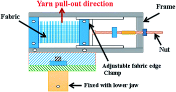
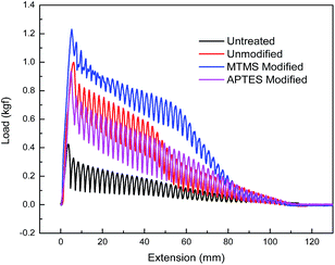
The tensile strength of the yarns was tested on a Universal Tensile Tester, Instron (Model 3365).31 The lower jaw was modified using an attachment to enable the pull-out of single or multiple yarns without producing any folds or distortions in the fabric samples (Fig. 1). The yarn pull-out test was carried out with a constant upper jaw speed of 500 mm min−1. A sample with 16 cm × 12 cm dimensions was cut, with a free length of 1.5 cm at each of the left and right extremities which can be used to fix the sample in the test frame of 9 cm width. The length of the sample was divided into two parts: the upper 8.5 cm had the yarns in the transverse direction removed; and the lower 7.5 cm was fabric left intact (Fig. 2). For each test sample around 10 tests were conducted and the average was taken.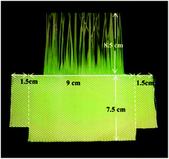 | ||
| Fig. 2 Fabric sample dimensions for the yarn pull-out test.23 | ||
2.8 Dynamic impact test
The impact resistance performance of untreated and STF-treated Kevlar fabrics was evaluated by a Falling Dart Type Impact Resistance Tester (CEAST, Model: FRACTOVIS PLUS, Italy) following the ASTM D 3763 method.32 The fabric sample size was 160 mm × 160 mm. The fabric samples were kept in between two circular sample holders with an inner diameter of 76 mm. A hemispherical impactor was used to hit the samples at a speed of 4.5 m s−1. The peak force and the energy absorbed at the peak force i.e. the peak energy and total energy were measured by the instrument. For each sample, four specimens were tested.3. Results and discussion
3.1 Characterization of the synthesized silica particles
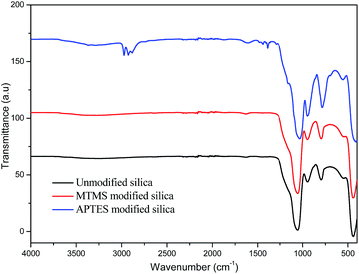
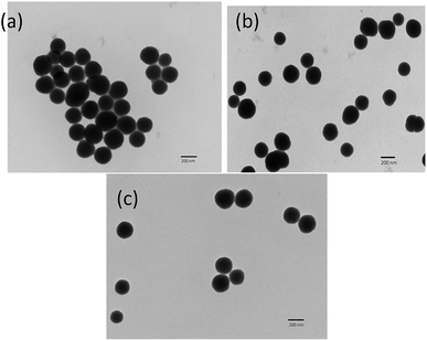
The synthesized silica particles as well as those modified by APTES and MTMS were analyzed by FTIR spectroscopy (Fig. 3). The bands observed at around 1066 cm−1, 936 cm−1 and 801 cm−1 due to asymmetric vibrations of Si–O,33,34 symmetric vibrations of Si–OH, and symmetric vibrations of Si–O bonds,34 respectively, confirmed the synthesis of silica. Upon modification with MTMS, no additional bands were observed, but upon modification with APTES, the bands centred at around 1612 cm−1 and at 1429 cm−1 appeared and were assigned to the NH2 deformation modes of the amine groups. Also, bands observed at around 2929 cm−1 and 2883 cm−1 were attributed to the stretching modes of CH2, suggesting the successful functionalization of silica particles with APTES.35,36TEM images of non-functionalized and functionalized silica particles are shown in Fig. 4. The figure confirms that there were no significant changes in the size or shape of the particles after modification. The particle diameter was measured using Image J software and the mean of 30 readings is reported in Table 1.
| Silica particles | Mean particle diameter (nm) |
|---|---|
| Unmodified | 215.6 ± 20.4 |
| MTMS modified | 221.2 ± 25.1 |
| APTES modified | 222.6 ± 16.4 |
The surface charges and modification of silica particles with APTES and MTMS were evaluated using the zeta potential (Zetasizer Nano ZS90) by dispersing the particles in ethanol. Before analysis, the pH of all the solutions was maintained at 6.7. The unmodified silica showed a negative zeta potential, i.e. −6.07 mV due to the deprotonated silanol groups (Table 2). Whereas, after modification with MTMS, the zeta potential of the modified silica particles shifted to +9.61 mV (Table 2), reflecting the interaction of the surface hydroxyl groups of silanol with the methoxy groups of MTMS, leaving the methyl groups of MTMS on the surface of the modified silica behind. On the other hand, in the case of APTES modified silica, the O–H groups of silanol interact with the methoxy groups of APTES which leaves the –NH2 groups on the surface of the modified silica particles behind and thus the overall zeta potential of the modified silica particles shifted to −10.9 mV (Table 2).
| Silica particles | Zeta potential (mV) |
|---|---|
| Unmodified | −6.07 |
| MTMS modified | +9.61 |
| APTES modified | −10.9 |
3.2 Rheological analysis of STFs
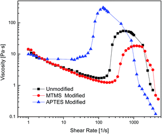
The rheological behavior of STFs made from all three particle types is shown in Fig. 5 and the values of the critical shear rate and peak viscosity are shown in Table 3. As can be seen, all three STFs exhibit shear thickening behavior, i.e. an increase in peak viscosity with an increase in shear rate. This is a really important aspect as it has been reported in the literature that the impact energy absorption by high performance fabrics treated with STF increases with increasing peak viscosity of the STF.4,8| STF | Critical shear rate (s−1) | Peak viscosity (Pa s) |
|---|---|---|
| Unmodified | 101 | 55 |
| MTMS modified | 172 | 18.3 |
| APTES modified | 20.4 | 304 |
From Fig. 5 and Table 3, it is noted that the STF based on APTES modified silica shows much higher peak viscosity (304 Pa s) as compared to the control STF (55 Pa s) at the same particle concentration. On the other hand, the STF based on MTMS modified particles shows much lower peak viscosity (18.3 Pa s) as compared to the control STF. The reason for this behavior can be attributed to the change in particle–particle and particle–medium interaction upon chemical modification of silica particles. In the case of the MTMS modified particles, the surface modification actually causes a reduction in particle–media interactions due to the hydrophilic nature of the medium (PEG) and the hydrophobic surface of the modified silica particles. This results in a delay of the onset of shear thickening indicated by the high critical shear rate (172 s−1) and the lowering of the peak viscosity (18.3 Pa s). In contrast, the STF prepared with APTES modified silica particles shows a lower critical shear rate (20.4 s−1) and higher peak viscosity (304 Pa s) as a consequence of the increased particle–particle and particle–medium interactions. The amino groups present on the surface of the silica particles cause improved interactions between silica particles and the PEG by increasing the tendency to form hydrogen bonds. The mechanism of the functionalization of silica with MTMS and APTES and their hydrocluster formation under shear force are shown in Scheme 1.
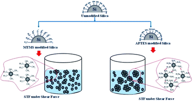 | ||
| Scheme 1 Hydrocluster formation under shear force in MTMS modified and APTES modified silica based STFs. | ||
3.3 Yarn pull-out force of Kevlar fabrics
STFs prepared using unmodified and modified silica particles were applied on Kevlar fabrics as explained in Section 2.5. The average weight add-on percentage of the fabrics after treatment was found to be 10.8, 11.0 and 9.7% for the unmodified, MTMS modified and APTES modified particle based STFs, respectively. Results for the yarn pull-out test are shown in Fig. 6 and the peak pull-out force values are given in Table 4.| Type of silica particle used in the STF | Peak pull-out force (gf) |
|---|---|
| Untreated fabric | 424 |
| Unmodified | 1000 |
| MTMS modified | 1230 |
| APTES modified | 935 |
The yarn pull-out force increases after the STF treatment irrespective of the type of silica particle. This implies that the presence of silica based STFs enhances fibre to fibre friction in Kevlar fabrics.8 However, Kevlar fabrics treated with STF based on MTMS modified particles show the highest (1230 gf) peak pull-out force and the value is the lowest for the fabrics treated with APTES modified STF. However, if one refers to the rheological data shown in Table 4, the results seem counter intuitive since the STF based on APTES modified silica particles exhibits much higher peak viscosity (304 Pa s) in comparison to MTMS modified silica based STF (18.3 Pa s).
3.4 Impact energy absorption by Kevlar fabrics
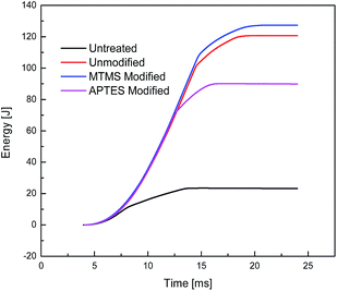
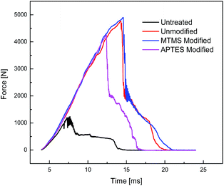
Untreated and STF treated Kevlar fabrics were subjected to impact testing and the results are shown in Table 5. The relevant time–energy and time–force graphs are shown in Fig. 7 and 8, respectively. The relative change in peak force, peak energy and total energy after the application of modified STFs is shown in Fig. 9. The results show that the application of STF increases the peak force and total energy absorbed by the fabric drastically. The fabric treated with MTMS modified silica based STF shows higher peak force and energy absorption (4901.8 N and 127.3 J, respectively) as compared to both unmodified STF (4766.4 N and 120.7 J, respectively) and APTES modified STF treated fabrics (4257.8 N and 90.1 J, respectively). APTES modified silica based STF treated fabrics show the lowest impact resistance performance among the three STF treated Kevlar fabrics. These results are similar to the yarn pull-out results discussed earlier. This seems contradictory since the MTMS based STF shows the lowest peak viscosity among the three.| Type of STF applied on the fabric | Peak viscosity of STF | Peak energy [J] | Peak force [N] | Total energy [J] |
|---|---|---|---|---|
| No STF | — | 9.2 | 1233.5 | 23.5 |
| Unmodified | Medium | 97.4 | 4766.4 | 120.7 |
| MTMS modified | Low | 105.3 | 4901.8 | 127.3 |
| APTES modified | High | 69 | 4257.8 | 90.1 |
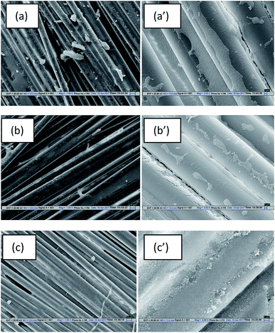
To find the root cause of this apparent contradiction between the rheological results of the STFs and the mechanical performance of Kevlar fabrics, the distribution pattern of STFs on the treated fabrics was studied using SEM micrographs as shown in Fig. 10. The SEM results clearly show that the distribution of the three different types of STF on Kevlar fabrics, treated under identical process conditions, is different. In the case of the unmodified STF (Fig. 9(a)), the STF is distributed on the fabric in such a way that part of it rests on the fibre surfaces and part of it is located between the fibres. In the case of the MTMS based STF (Fig. 9(b)), most of it is distributed between the filaments and very little STF is dispersed over the fibre surfaces. This can be attributed to the fact that Kevlar is a hydrophilic fibre and MTMS modified silica particles are also largely hydrophobic in character. Hence when this STF is applied on the Kevlar fabric, due to their incompatible nature, the STF tries to concentrate in the inter-fibre and inter-yarn space due to a poor interaction between the hydrophobic particle surface and the hydrophilic substrate. Since the STF acts primarily by increasing friction at low shear rates and shear thickening at higher shear rates, its distribution on the substrate plays a very important role in determining the impact resistance characteristics of the treated material. In the case of the MTMS modified silica based STF, even though it exhibits the lowest peak viscosity among the three STFs, most of it is present between the filaments and between the yarns. Hence it is most effective in influencing the properties which are affected by its distribution viz, yarn pull-out and impact energy absorption. The APTES based STF (Fig. 9(c)) can be seen to be uniformly distributed on the Kevlar fabric. This happens due to a similarity between the APTES and substrate (Kevlar) in terms of the presence of amino end groups on both. This leads to better interactions between amino groups of Kevlar and APTES modified particles. As a result, uniform distributions of APTES based STFs can be seen over the Kevlar fabric. Since most of the STF is spread over the fibre and yarn surfaces, less of it is available between the filaments and between the yarns. Hence, even though this STF shows the highest peak viscosity, it is the least effective in improving the impact resistance performance of the treated fabrics. In fact, its performance is poorer than that of the STF synthesized with the unmodified silica particles. The phenomenon of impact energy absorption by MTMS and APTES modified silica based STF treated Kevlar fabrics is depicted in Scheme 2. The results thus obtained show that particle surface modification can be used as an approach to tune the impact performance of STF treated fabrics further.
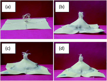 | ||
| Fig. 10 STF treated fabric prepared from different silica particles after impact tests on (a) untreated, (b) unmodified, (c) MTMS modified, and (d) APTES modified particles. | ||
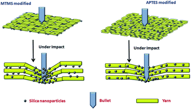 | ||
| Scheme 2 Impact energy absorption phenomenon in MTMS and APTES modified silica based STF treated Kevlar fabrics. | ||
Images of Kevlar fabrics after the impact tests are shown in Fig. 10. It can be seen that in the case of the untreated fabric, the failure involves extensive yarn pull-out from the zone of impact (Fig. 10(a)). However, in the case of the STF treated fabrics (Fig. 10(b)–(d)), yarn failure accompanied by a dome formation is clearly visible. This signifies that the secondary yarns which are away from the zone of impact also participate in energy absorption as they are engaged in higher inter-yarn friction and thickening of the STF. The detailed analysis of impact absorption modes in STF treated fabrics has been discussed elsewhere.37
4. Conclusions
Surface modification of spherical silica particles, synthesized using the Stöber method, was carried out using silanes of hydrophilic (APTES) and hydrophobic (MTMS) nature. It was observed that STF (70% wt/wt) prepared with MTMS modified silica particles showed lower peak viscosity and higher critical shear rate as compared to STF prepared with unmodified and APTES particle based STFs. This is attributed to the presence of hydrophobic groups on the silica particle surface in the case of MTMS, resulting in decreased particle–particle and particle–medium interactions. The highest peak viscosity was exhibited by the STF prepared with APTES modified silica particles due to enhanced particle–media interactions. However, the MTMS modified STF treated Kevlar fabrics showed the highest peak yarn pull-out force and impact energy absorption and the lowest corresponding values were obtained with Kevlar fabrics treated with STF based on APTES modified silica particles. This conflicting rheological and mechanical behavior was due to the different STF–substrate interactions based on the hydrophobicity or hydrophilicity of the silica particles. Chemical modification helps to push MTMS based STF more in the inter-fibre and yarn spaces due to its incompatibility with the hydrophilic Kevlar substrate. On the contrary, uniform distribution of APTES based STF on the Kevlar substrate leaves only little of it in the inter-fibre and inter-yarn spaces to influence the yarn pull-out and impact energy absorption results. Hence chemical modification of the solid phase of STF can be used to tune the yarn pull-out and impact energy absorption by the STF treated Kevlar fabrics.Conflicts of interest
There are no conflicts to declare.Acknowledgements
The research was financially supported by CSIR (Project No. 22(0664)/14/EMR-II), India.Notes and references
- A. Srivastava, A. Majumdar and B. S. Butola, Mater. Sci. Eng., A, 2011, 529, 224 CrossRef CAS.
- A. Tarig, T. A. Hassan, V. K. Rangari and S. Jeelani, Mater. Sci. Eng., A, 2010, 527, 2892 CrossRef.
- F. S. Luz, E. P. L. Junior, L. H. L. Louro and S. N. Monteiro, Mater. Res., 2015, 18, 170 CrossRef.
- A. Majumdar, B. S. Butola and A. Srivastava, Mater. Des., 2014, 54, 295 CrossRef CAS.
- M. J. Decker, C. J. Halbach, C. H. Nam, N. J. Wagner and E. D. Wetzel, Compos. Sci. Technol., 2007, 67, 565 CrossRef CAS.
- Y. S. Lee, E. D. Wetzel and N. J. Wagner, J. Mater. Sci., 2003, 38, 2825 CrossRef CAS.
- N. J. Wagner and J. F. Brady, Phys. Today, 2009, 62, 27 CrossRef CAS.
- S. Gürgen and M. C. Kushan, Composites, Part A, 2017, 94, 50 CrossRef.
- Y. Duan, M. Keefe, T. A. Bogetti and B. S. Cheeseman, Int. J. Impact Eng., 2005, 31, 996 CrossRef.
- D. Zhu, C. Soranakom, B. Mobasher and S. D. Rajan, Composites, Part A, 2011, 42, 868 CrossRef.
- K. Bilisik, Composites, Part A, 2011, 42, 1930 CrossRef.
- G. Nilakantan, R. L. Merrill, M. Keefe, J. W. Gillespie Jr and E. D. Wetzel, Composites, Part B, 2015, 68, 215 CrossRef CAS.
- H. Mahfuz, F. Clements, V. Rangari, V. Dhanak and G. Beamson, J. Appl. Phys., 2009, 105, 064307 CrossRef.
- R. Joselin and W. J. Wilson, Def. Sci. J., 2014, 64, 236 CrossRef CAS.
- J. Qin, G. Zhang, Z. Ma, J. Li, L. Zhou and X. Shi, RSC Adv., 2016, 6, 81913 RSC.
- J. Qin, G. Zhang, L. Zhou, J. Li and X. Shi, RSC Adv., 2017, 7, 39803 RSC.
- M. Fahool and A. R. Sabet, Int. J. Impact Eng., 2016, 90, 61 CrossRef.
- X. Gong, Y. Xu, W. Zhu, S. Xuan, W. Jiang and W. Jiang, J. Compos. Mater., 2014, 48, 641 CrossRef.
- A. Harish, H. P. Lee, T. E. Tay and V. B. C. Tan, Int. J. Impact Eng., 2015, 80, 143 CrossRef.
- Y. Park, Y. H. Kim, A. B. Baluch and C.-G. Kim, Compos. Struct., 2015, 125, 520 CrossRef.
- W. Stöber and A. Fink, J. Colloid Interface Sci., 1968, 26, 62 CrossRef.
- I. A. Rahman and V. Padavettan, J. Nanomater., 2012, 2012, 15 Search PubMed.
- I. A. M. Ibrahim, A. A. F. Zikry and M. A. Sharaf, J. Am. Sci., 2010, 6, 985 Search PubMed.
- S. Gürgen, W. Li, M. C. Kuşhan and W. Li, Prog. Polym. Sci., 2017 DOI:10.1016/j.progpolymsci.2017.07.003.
- M. Hasanzadeh and V. Mottaghitalab, J. Mater. Eng. Perform., 2014, 23, 1182 CrossRef CAS.
- S. Gürgen, W. Li and M. C. Kuşhan, Mater. Des., 2016, 104, 312 CrossRef.
- N. J. Wagner and J. F. Brady, Phys. Today, 2009, 62, 27 CrossRef CAS.
- S. R. Raghavan, H. J. Walls and S. A. Khan, Langmuir, 2000, 16, 7920 CrossRef CAS.
- S. Li, J. Wang, S. Zhao, W. Cai, Z. Wang and S. Wang, Ceram. Int., 2016, 4, 7767 CrossRef.
- K. Yu, H. Cao, K. Qian, X. Sha and Y. Chen, J. Nanopart. Res., 2012, 14, 9 Search PubMed.
- A. Majumdar and A. Laha, Text. Res. J., 2016, 86, 2056 CrossRef CAS.
- A. Majumdar, B. S. Butola, N. Awasthi, I. Chauhan and P. Hatua, Polym. Compos., 2017 DOI:10.1002/pc.24346.
- M. A. Karakassides, D. Gournis and D. Petridis, Clay Miner., 1999, 34, 429 CrossRef CAS.
- B. J. Saikia, G. Parthasarathy and N. C. Sarmah, Nat. Sci., 2009, 7, 45 Search PubMed.
- N. Majoul, S. Aouida and B. Bessaïs, Appl. Surf. Sci., 2015, 331, 388 CrossRef CAS.
- Y. Wang, Y. Sun, J. Wang, Y. Yang, Y. Li, Y. Yuan and C. Liu, ACS Appl. Mater. Interfaces, 2016, 8, 17166 CAS.
- A. Srivastava, A. Majumdar and B. S. Butola, Mater. Des., 2013, 51, 148 CrossRef.
| This journal is © The Royal Society of Chemistry 2017 |

