
 Open Access Article
 This Open Access Article is licensed under a
 Creative Commons Attribution 3.0 Unported Licence
Hybridizing Fe3O4 nanocrystals with nitrogen-doped carbon nanowires for high-performance supercapacitors†
Jizhang Chen *a,
Qiongyu Chena,
Junling Xub and
Ching-Ping Wongb
*a,
Qiongyu Chena,
Junling Xub and
Ching-Ping Wongb
aCollege of Materials Science and Engineering, Nanjing Forestry University, Nanjing 210037, China. E-mail: jizhang.chen@hotmail.com
bDepartment of Electronic Engineering, The Chinese University of Hong Kong, New Territories, Hong Kong
First published on 12th October 2017
Abstract
This study develops a facile approach to anchor Fe3O4 nanocrystals uniformly onto nitrogen-doped carbon nanowires (NCN). The influence of the ratio of Fe3O4 to NCN on the structure and pseudocapacitance performance of the nanocomposite is investigated systematically. It is found that the best performance is realized when the mass percentage of Fe3O4 is 65.9%. Benefiting from the synergistic effect of the nanostructure and conductive matrix, the optimized nanocomposite delivers high specific capacitance (541.7 F g−1 at 1 A g−1), superior rate capability (337.1 F g−1 at 10 A g−1), as well as good cyclability. This nanocomposite is also used as the anode material for assembling an asymmetric supercapacitor, which exhibits a high specific energy of 59.1 W h kg−1 and high specific power of 17.85 kW kg−1. The results manifest the great potential of this nanocomposite for next-generation high-power applications.
Introduction
Among various electrochemical energy storage devices, supercapacitors are well-known for their high specific power and long life span, thus holding great promise for a wide range of applications, such as energy recovery systems, backup power systems, smart grids, and high-rate power sources (e.g., mining shovels and mobile laser weapons).1 According to different charge storage mechanisms, supercapacitors can be classified as electric double-layer capacitors (EDLCs) and pseudocapacitors.2 EDLCs beat batteries in terms of specific power, whereas their specific energy is rather low, due to the fact that the energy storage of EDLCs is based on surface ion adsorption.3 Unlike EDLCs, pseudocapacitors store charges via surface and near-surface redox reactions, as a result, their specific energy is significantly higher than that of EDLCs.4 Therefore, pseudocapacitors are now considered as promising alternative or complement to batteries, especially under the circumstances when high power delivery and/or fast energy harvesting are required. Nevertheless, the specific energy of currently developed pseudocapacitors is still much lower than that of batteries due to the following two reasons. One reason is that the interior bulk of pseudocapacitive materials hardly contributes to the energy storage, due to poor electronic and ionic conductivities. The other is that aqueous electrolytes in pseudocapacitors have a relatively narrow electrochemical stability window (<2.0 V).In order to push forward the technology of supercapacitors, many research efforts have been devoted to exploring high-capacitance pseudocapacitive materials. At present, Fe-based materials are regarded as the best anode candidates for pseudocapacitors, principally because of their suitable negative working window and large theoretical specific capacitance.4–8 Besides, these materials, including Fe2O3, Fe3O4, FeOOH, FeS2, and FeWO4, are earth-abundant, cost-effective, less toxic, and environmentally benign. However, these materials suffer from sluggish charge transports, which make their practical capacitances oftentimes much lower than the theoretically predicted values. To tackle such limitation, three strategies have been proposed to tailor the morphology and structure of Fe-based pseudocapacitive materials. The first strategy is to construct nanostructures, like thin film,9,10 nanoparticles,11 nanorods,12–14 nanoneedles,15 nanowires,16 nanobelts,17 nanotubes,18 nanosheets,19 nanoflakes,20 so as to enlarge surface active sites and shorten charge transport distances. The second strategy extends the first one by employing hollow or porous structures, which render sufficient exposure of active sites to the electrolyte.21–24 The third strategy is to build heterostructures that incorporate Fe-based materials with electrically conductive matrixes, e.g., graphene,25–29 carbon nanotubes (CNTs),30 carbon nanofibers (CNFs),31 poly(3,4-ethylenedioxythiophene) (PEDOT),32,33 polyaniline (PANI),34 by taking advantage of fast electronic transport of the matrixes. These strategies can in principle facilitate charge transports, thus reducing electrochemical polarization and enhancing pseudocapacitive kinetics.
Previously, we reported graphene/porous Fe2O3 nanocomposite, which combines the merits of the above-mentioned three strategies.35 Although excellent pseudocapacitive performances were obtained, the synthesis procedure is too complicated to be scaled up. In this study, we focus on improving the performance of magnetite Fe3O4, whose electrical conductivity is more than 16 orders of magnitude higher than that of hematite Fe2O3.36,37 High specific capacitance, superior rate capability, and good cyclability are realized through introducing nitrogen-doped carbon nanowires (NCN) as the conductive matrix. Moreover, the synthesis method is facile, scalable, and cost-effective. We also assemble an asymmetric supercapacitor (ASC) device by using NCN@Fe3O4 and CNT@Co–Ni layered double hydroxide (LDH) as the anode and cathode materials, respectively. The device exhibits both high specific energy and high specific power.
Experimental procedure
Materials synthesis
Typically, 125 mL aqueous solution containing 0.02 M cetyl trimethyl ammonium bromide (CTAB) and 0.02 M oxalic acid was stirred at room temperature until CTAB was completely dissolved. Then, this solution was added by 0.275 mL pyrrole and stirred for 1 h, followed by the addition of 20 mL 0.2 M ammonium persulfate (APS) aqueous solution. After 4 h vigorous stirring at room temperature, black precipitate (polypyrrole (PPy) nanowires) was centrifugated out and washed with de-ionized (DI) water and ethanol. Around 200 mg PPy per batch was obtained. For the synthesis of NCN@Fe3O4, 400 mg PPy nanowires were dispersed into 40 mL ethanol containing certain amount of Fe(NO3)3·9H2O by sonication and stirring. Subsequently, the solution was kept at stirring at 50 °C until ethanol was completely evaporated. Finally, the resultant product was annealed in a tube furnace at 550 °C for 2 h under an Ar stream. Through varying the amount of Fe(NO3)3·9H2O, NCN@Fe3O4 products with different mass ratio of Fe3O4 to NCN were obtained. That is, 0.994, 1.987, 2.982, and 3.976 g Fe(NO3)3·9H2O led to the formation of NCN@Fe1, NCN@Fe2, NCN@Fe3, and NCN@Fe4, corresponding to the stoichiometric mass ratio of Fe3O4 to NCN being 1![[thin space (1/6-em)]](https://www.rsc.org/images/entities/char_2009.gif) :1, 2:1, 3:1, and 4:1, respectively. For comparison, neat NCN was obtained by annealing PPy nanowires at 550 °C for 2 h under Ar atmosphere without the addition of Fe(NO3)3·9H2O. On average, 200 mg PPy nanowires can generate 98.4 mg NCN.
:1, 2:1, 3:1, and 4:1, respectively. For comparison, neat NCN was obtained by annealing PPy nanowires at 550 °C for 2 h under Ar atmosphere without the addition of Fe(NO3)3·9H2O. On average, 200 mg PPy nanowires can generate 98.4 mg NCN.
Characterization
Field emission scanning electron microscope (FE-SEM, NOVA NanoSEM 230, FEI) and transmission electron microscope (TEM, JEM-2100F, JEOL) equipped with an energy dispersive X-ray spectroscopy (EDX) detector were used to characterize the morphology, structure, and elemental compositions. X-ray diffraction (XRD) patterns were collected using a Da Vinci D8 ADVANCE diffractometer with Cu Kα radiation source (λ = 0.1540598 nm). Raman spectra were recorded from a Thermo Scientific DXR Raman Spectrometer (λ = 532 nm). The mass ratios of Fe3O4 to NCN were measured on a thermogravimetric analyzer (TGA, Q5000 IR, TA Instruments) by heating samples in O2 from 50 to 900 °C at a heating rate of 10 °C min−1. Investigation of the surface chemical composition was performed on an X-ray photoelectron spectroscopy (XPS, ESCALAB 250Xi, Thermo Scientific).Electrochemical measurements
A slurry of 80 wt% active material, 10 wt% carbon black (Super-P), and 10 wt% polyvinylidene difluoride (PVDF) dispersed in N-methylpyrrolidone (NMP) was pasted onto nickel foams and then dried at 110 °C under vacuum for 12 h. Three-electrode measurements were performed on a CHI 660E electrochemical workstation using the obtained Ni foam electrode, Pt plate, Hg/HgO electrode (1 M KOH), and 3 M KOH aqueous solution as the working electrode, counter electrode, reference electrode, and electrolyte, respectively. Cyclic voltammetry (CV) and galvanostatic charging/discharging (GCD) tests were conducted at different scan rates and current densities (based on the total bass of NCN and Fe3O4). Electrochemical impedance spectroscopy (EIS) measurements were carried out with frequency ranging from 10 mHz to 100 kHz and the amplitude being set at 5 mV. For two-electrode measurements, NCN@Fe2, CNT@Co–Ni LDH, and 3 M KOH aqueous solution served as the negative electrode material, positive electrode material, and electrolyte, respectively, to assemble an ASC device. The synthesis process of CNT@Co–Ni LDH can be found in our previous report.35 Prior to the ASC assembly, the mass ratio of NCN@Fe2 to CNT@Co–Ni LDH was balanced according to: q+ = q−. CV and GCD tests were carried out on the basis of the total mass of NCN@Fe2 and CNT@Co–Ni LDH.Results and discussion
Fig. 1(a) depicts the schematic for fabricating NCN@Fe2. First, nitrogen-rich PPy nanowires were synthesized by a facile solution method. Then, Fe(NO3)3 as the Fe precursor was casted onto the surface of PPy nanowires, followed by calcination at 550 °C in Ar, during which PPy was carbonized, accompanied by the transformation of Fe3+ precursor into Fe3O4. As such, Fe3O4 was anchored onto the surface of NCN. The SEM images of PPy and NCN are shown in Fig. S1 (ESI†), suggesting that PPy has a nanowire morphology while NCN inherits that morphology. Fig. 1(b)–(d) reveal that NCN@Fe2 is also composed of nanowires, implying that Fe3O4 is anchored on NCN uniformly. By comparing Fig. S1(d) and (e)† (NCN) and Fig. 1(c) and (d) (NCN@Fe-2), we can see that the edge of nanowires becomes indistinct in NCN@Fe2, due to the coating of Fe3O4. If further comparing higher magnification TEM images in Fig. 1(e) and S1(f),† we can clearly see that NCN is decorated with Fe3O4 nanocrystals in NCN@Fe2. The selected area electron diffraction (SAED) pattern in the inset of Fig. 1(e) displays six rings, which are in good agreement with (220), (311), (400), (422), (511), and (440) crystalline planes of Fe3O4 (JCPDS 65-3107) with a cubic lattice system from the inner to the outer. The formation of Fe3O4 is further evidenced by the high-resolution (HR) TEM image in Fig. 1(f), which exhibits lattice spacings of 0.25, 0.49, and 0.21 nm, matching well with the (311), (111), and (400) planes of Fe3O4, respectively. In order to study the elemental distribution in NCN@Fe2, we employed EDX mapping, as shown in Fig. 1(g). Fe and O elements are observed to coincide with C element, confirming the formation of Fe3O4 on the NCN surface.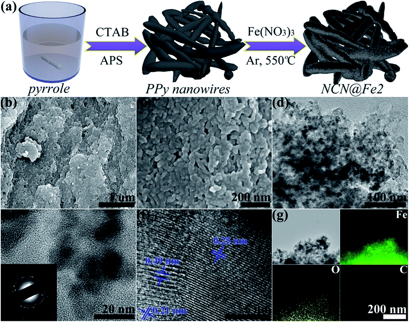 | ||
| Fig. 1 (a) Illustration of the fabrication process, (b, c) SEM images, (d–f) TEM images, and (g) EDX elemental maps of NCN@Fe2. | ||
The crystalline structures of the products were identified by XRD measurements and the resultant patterns are presented in Fig. 2(a). In NCN, two humps centered at around 27.5° and 42.0° arise from (002) and (100) planes of the pseudographitic carbon, indicative of poor ordering of graphene domains.38 After the incorporation of Fe3O4, all products show nearly identical patterns and the two humps from NCN still exist, implying small particle size and low crystallinity of Fe3O4. Take NCN@Fe2 for example, the peaks at 30.1°, 35.5°, 43.0°, 56.9°, and 62.5° can be indexed as (220), (311), (400), (511), and (440) planes of Fe3O4. In order to investigate the formation process of NCN@Fe3O4, we also used XRD technique to characterize different products when the raw material or annealing temperature was altered, as shown in Fig. S2 (ESI†). It can be seen that the Fe(NO3)3·9H2O precursor was hydrolyzed to Fe(OH)3 after the ethanol solvent was evaporated. The Fe(OH)3 can be bound to PPy nanowires due to the mutual effects of surface adsorption and electrostatic interaction. Then during the annealing process, Fe(OH)3 was converted to Fe3O4, producing NCN@Fe3O4.
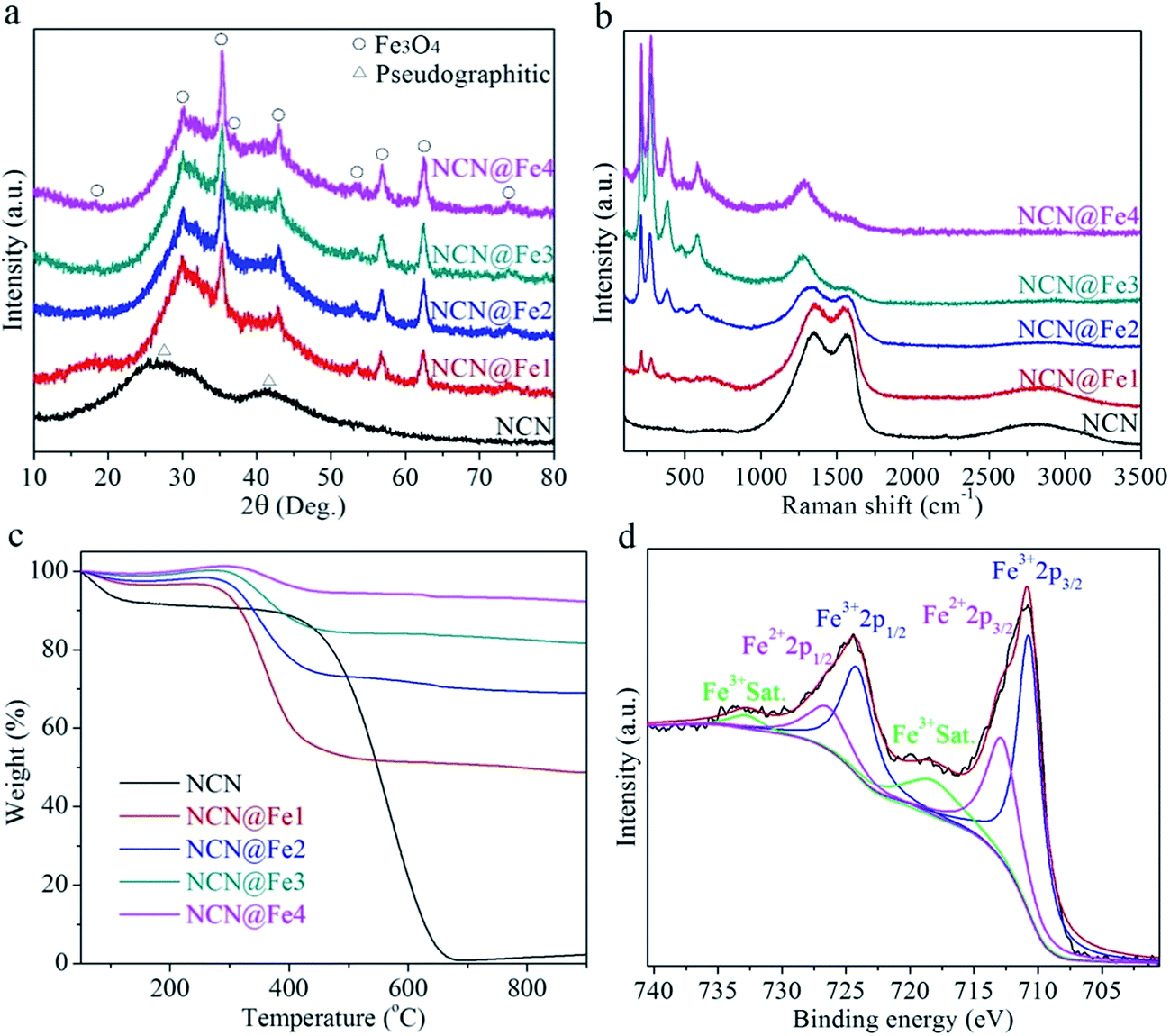 | ||
| Fig. 2 (a) XRD patterns, (b) Raman spectra, (c) TG curves of NCN, NCN@Fe1, NCN@Fe2, NCN@Fe3, and NCN@Fe4. (d) Fe 2p HR XPS spectrum of NCN@Fe2. | ||
Raman measurements were also conducted to further confirm the phase and composition of NCN-based products, as shown in Fig. 2(b). NCN exhibits a broad disorder-induced D band at ∼1359 cm−1 and a broad graphitic in-plane vibrational G band at ∼1575 cm−1, which are two typical bands of carbonaceous materials.35,39 Besides, there exists a hump from 2500 to 3200 cm−1, relating with 2D and D + G bands. After the introduction of Fe3O4, five new peaks appear in the low frequency region of 100 to 1000 cm−1. These peaks are all characteristic of Fe3O4, i.e. Eg mode (212, 275, 387 and 479 cm−1) and A1g mode (585 cm−1).40,41 As the content of Fe3O4 increases, the intensity of these peaks becomes stronger. In addition to these peaks, broad peaks at ∼1280 cm−1 also come from Fe3O4.40,41 Different from XRD measurements, the intensity of Raman bands from NCN decreases considerably when increasing the amount of Fe3O4, due to different detection depth of XRD and Raman techniques.
TG analysis was conducted in O2 atmosphere to determine the weight percentages of Fe3O4 in the NCN-based products. During high-temperature treatment, Fe3O4 was oxidized to Fe2O3, while NCN was burnt into CO2. According to the weight loss in the TG curves (Fig. 2(c)), the weight percentages of Fe3O4 are estimated to be 45.9%, 65.9%, 78.4%, and 89.0% in NCN@Fe1, NCN@Fe2, NCN@Fe3, and NCN@Fe4, respectively. XPS characterization was carried out to study the chemical contents and valence states in NCN@Fe2, as shown in Fig. 2(d) and S3 (ESI†). The survey spectrum in Fig. S3(a)† exclusively reveals C, O, Fe, and N elements, demonstrating the dispersion of iron oxide in N-doped carbon matrix. In Fig. 2(d), the HR XPS spectrum for the Fe 2p core level is consistent with that of Fe3O4 in other reports.42 Two main peaks at 710.7 eV and 724.1 eV accompanied by their satellite peaks at 718.2 and 732.8 eV are characteristic of Fe3+, while 712.8 and 726.4 eV are assigned to Fe2+ 2p3/2 and Fe2+ 2p1/2, respectively.13 The deconvolution of the C 1s HR spectrum is exhibited in Fig. S3(b).† The most pronounced peaks is located at 284.7 eV, which is characteristic of the sp2 graphitic lattice (C–C and C![[double bond, length as m-dash]](https://www.rsc.org/images/entities/char_e001.gif) C), while three other subpeaks at 288.1, 286.2, and 285.4 eV are associated with O–CO, CN (& CO), and C–N (& C–O) functional groups, respectively.43 In Fig. S3(c),† the N 1s signal is derived from the NCN matrix, and contains three subpeaks at 400.3, 399.4, and 398.7 eV, corresponding to quaternary N, pyrrolic N, and pyridinic N, respectively.44,45 Specifically, the N doping can donate extra electrons that increase the electrical conductivity. And the O 1s HR spectrum (Fig. S3(d)†) can be fitted into four peaks at 533.4, 532.1, 531.3, and 530.3 eV, in accordance with absorbed water, O–C, OC, and O–Fe, respectively.43,46
C), while three other subpeaks at 288.1, 286.2, and 285.4 eV are associated with O–CO, CN (& CO), and C–N (& C–O) functional groups, respectively.43 In Fig. S3(c),† the N 1s signal is derived from the NCN matrix, and contains three subpeaks at 400.3, 399.4, and 398.7 eV, corresponding to quaternary N, pyrrolic N, and pyridinic N, respectively.44,45 Specifically, the N doping can donate extra electrons that increase the electrical conductivity. And the O 1s HR spectrum (Fig. S3(d)†) can be fitted into four peaks at 533.4, 532.1, 531.3, and 530.3 eV, in accordance with absorbed water, O–C, OC, and O–Fe, respectively.43,46
CV and GCD measurements were performed in a three-electrode setup to evaluate electrochemical performances of NCN, NCN@Fe1, NCN@Fe2, NCN@Fe3, and NCN@Fe4. Fig. 3(a) compares CV curves of different products at a scan rate of 5 mV s−1. The CV curve of NCN is similar to the rectangular, which is characteristic of EDCL materials. And NCN yields the lowest integral area among all the products, indicating its low specific capacitance. After Fe3O4 is introduced, the products exhibit redox peaks at around −0.97 and −0.66 V, quite different from that of NCN, suggesting the energy storage process is dominated by faradaic redox reactions. Moreover, the separation between cathodic and anodic peaks is merely 0.31 V, considerably lower than 0.48 V of Fe2O3 in our previous report.35 Such small separation is likely to originate from the high electrical conductivity of Fe3O4, which is in favor of electronic transports and therefore reduces electrochemical polarization. It is also observed that the weight percentage of Fe3O4 has an influence on the CV profile. NCN@Fe1 shows the minimum redox peaks, while NCN@Fe2 reveals the most prominent anodic peak. The rate-dependent CV curves of NCN@Fe2 are displayed in Fig. 3(b). As the scan rate is progressively increased, the anodic peak moves to higher potential, while the cathodic peak shifts to lower potential, due to stronger electrochemical polarization at a higher rate. At a low scan rate, electrons and electrolyte ions are provided with sufficient time to access the reaction sites of Fe3O4. When the scan rate is high, however, the charge transports within Fe3O4 cannot be synchronized with the rapid transfer of electrons in the external circuit. As a result, the accumulated electrons on the electrode would increase potential for charging and decrease potential for discharging. Notably, the separation between redox peaks is still low (0.405 V) at 50 mV s−1, suggesting fast redox kinetics of NCN@Fe2.
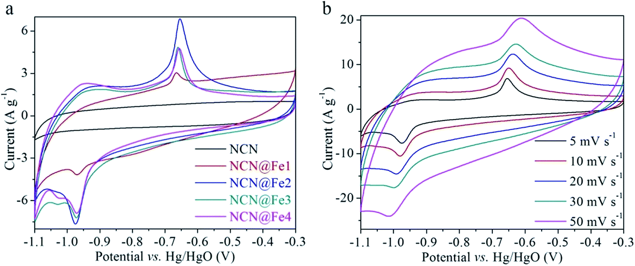 | ||
| Fig. 3 (a) Comparative CV curves of NCN, NCN@Fe1, NCN@Fe2, NCN@Fe3, and NCN@Fe4 at 5 mV s−1. (b) CV curves of NCN@Fe2 at different scan rates. | ||
GCD curves of NCN, NCN@Fe1, NCN@Fe2, NCN@Fe3, and NCN@Fe4 are compared in Fig. 4(a). These GCD curves are consistent with the CV curves in Fig. 3(a). The NCN curve shows typical triangle shape of EDLCs, while Fe3O4-containing products show charging and discharging plateaus that are associated with the pseudocapacitive characteristic. Similar to the CV results, NCN@Fe2 reveals the most developed plateaus. In contrast, the plateaus of NCN@Fe4 are indistinct, which might result from too much Fe3O4 anchored on the NCN, setting a barrier for charge transports. Fig. 4(b) presents GCD curves of NCN@Fe2 at different current densities. The charging and discharging curves are approximately symmetric throughout all the current densities, suggesting good reversibility of NCN@Fe2. At 1 A g−1, the charging and discharging plateaus are situated at −0.675 and −0.932 V, respectively. The corresponding separation (0.257 V) is smaller than that of the 5 mV s−1 CV curve. In addition, abrupt potential drops are observed at the beginning of the discharging curves, which originate from the equivalent series resistance (RESR). The RESR is mainly comprised of the intrinsic resistance of electrode and the ionic resistance from the electrolyte. Herein, the RESR average is calculated to be merely 0.87 Ω.
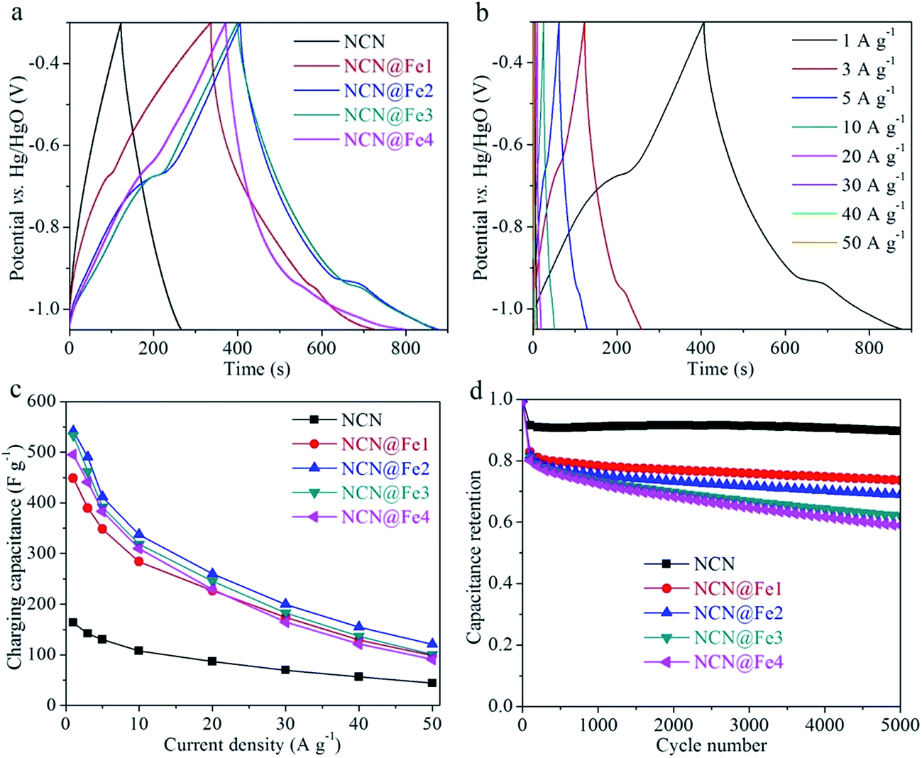 | ||
| Fig. 4 (a) Comparative GCD curves at 1 A g−1, (c) rate performances and (d) cycling performances of NCN, NCN@Fe1, NCN@Fe2, NCN@Fe3 and NCN@Fe4. (b) GCD curves of NCN@Fe2 at different current densities. | ||
Fig. 4(c) summarizes the rate-dependent specific capacitances of NCN, NCN@Fe1, NCN@Fe2, NCN@Fe3, and NCN@Fe4. The capacitance values are calculated on the basis of the charging curves, according to the calculation procedure described in our previous reports.35,39,47 NCN gives the lowest capacitances among all the products while NCN@Fe2 gives the largest capacitance throughout all the current densities. The reason why NCN@Fe2 possesses the best rate capability is that it contains a suitable amount of Fe3O4. If the percentage of Fe3O4 is too low, the capacitance of the composite would certainly be constrained. Otherwise if the percentage is too high, the charge transports within Fe3O4 would be insufficient. The charging capacitance of NCN@Fe2 reaches 541.7 F g−1 at 1 A g−1, while still maintaining 337.1, 199.2, and 121.0 F g−1 at 10, 30, and 50 A g−1, respectively. Impressively, NCN@Fe2 is superior to many Fe-based pseudocapacitive materials reported in recent three years, such as the ones listed in Table S1 (ESI†), including Ti-doped Fe2O3@PEDOT (311.6 F g−1),33 Fe2O3 nanotubes (300.1 F g−1),18 graphene/FeOOH QDs (365 F g−1),28 rGO/Fe3O4 nanoparticles (241 F g−1),48 Fe3O4@hollow graphite (481 F g−1),19 Fe2O3@MnO2 nanotubes (289.9 F g−1),49 Fe2O3 nanorods (516.7 F g−1),14 etc.
Cycling stability is another important parameter. Fig. 4(d) shows capacitance retentions of different products as a function of the cycle number. After 5000 cycles, NCN retains rather high capacitance retention of 89.7%, which is characteristic of EDLC materials. As the weight percentage of Fe2O3 rises progressively, the cyclability deteriorates gradually. This phenomenon is due to the intrinsic low cyclability of pseudocapacitive materials, that is, the large volumetric and structural changes during redox reactions inevitably bring in large capacitance loss upon repeated cycles. The NCN matrix can function as a buffer to relax these changes, resulting in better cyclability when more NCN is employed. As for NCN@Fe2, its capacitance retention is 68.9% after 5000 cycles. EIS measurements were also carried out to study different NCN-based products, as shown in Fig. S4 (ESI†). The Nyquist plots were fitted with the EC-Lab software using an equivalent circuit of R1 + C1/R2 + C2/(W1 + R3). The bulk resistance R1 of NCN, NCN@Fe1, NCN@Fe2, NCN@Fe3, and NCN@Fe4 is determined to be 0.559, 0.569, 0.573, 0.565, and 0.575 Ω, respectively. There is no obvious increase in R1 when increasing the mass ratio of Fe3O4 to NCN, implying high electrical conductivity of Fe3O4. Besides, the charge transfer impedance R3 of all the NCN-based products is lower than 1 Ω, indicative of fast interface kinetics.
To further evaluate the NCN@Fe2 (the best performed NCN@Fe3O4), we fabricated ASC devices using NCN@Fe2 and CNT@Co–Ni LDH as the anode and cathode materials, respectively. The CNT@Co–Ni LDH was reported by us previously.35 Because the potential windows of NCN@Fe2 and CNT@Co–Ni LDH are compatible, the ASC can deliver a high open-circuit voltage of 1.6 V, as shown in Fig. 5(a). These GVD curves are nonlinearly correlated with the potential, indicating pseudocapacitive behaviors. As the current density increases from 1, 6, to 18 A g−1, the discharging capacitance of the ASC (calculated based on the total mass of NCN@Fe2 and CNT@Co–Ni LDH) decreases from 174.5, 107.8, to 51.7 F g−1, respectively, exhibiting superior rate capability. Ragone plots of specific energy vs. specific power are displayed in Fig. 5(b), where the values of several state-of-the-art Fe-based ASCs reported in recent three years are also plotted.9,14,15,20,50–56 Our device exhibits high specific energy of 59.1 W h kg−1 under 937 W kg−1. Even when the specific power is increased to 4970 and 17850 W kg−1, the specific energy of our ASC still maintains 32.2 and 4.5 W h kg−1, respectively. Such energy-power performance outperforms many other Fe-based ASCs, such as Fe2O3 nanoflakes/PPy nanoleaves//MnO2 nanosheets ASC (42.4 W h kg−1 at 269 W kg−1),50 Fe2O3 nanoneedles//MnO2 nanosheets ASC (34.1 W h kg−1 at 3198 W kg−1),15 Fe2O3 nanorods//CoMoO4@NiMoO4 ASC (41.8 W h kg−1 at 700 W kg−1),14 rGO/Fe2O3 composite//CuCo2O4/CuO nanowires ASC (9.1 W h kg−1 at 8000 W kg−1).55 The above-mentioned good performances of NCN@Fe2 can be ascribed to the following four facts. First, NCN offers a highly conductive path for electrons. Second, the tiny particle size of Fe3O4 not only provides sufficient redox reaction sites but also facilitates charge transports within Fe3O4. Third, NCN can accommodate volumetric expansions of Fe3O4, therefore preventing Fe3O4 from decaying during long cycles. Last but not least, Fe3O4 is an electrical conductor, which allows for rapid electronic transports.
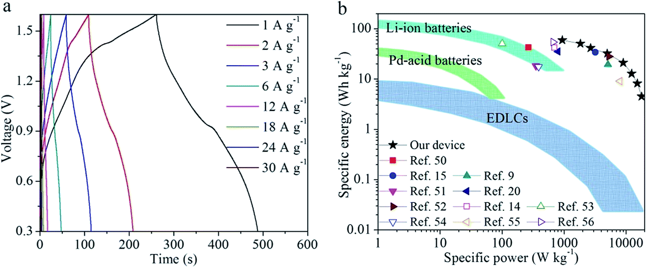 | ||
| Fig. 5 (a) GCD curves of NCN@Fe2//CNT@Co–Ni LDH ASC device at different current densities. (b) Ragone plots of specific energy vs. specific power for our ASC device in comparison with other Fe-based ASCs reported in recent three years. | ||
Conclusions
In summary, we have developed a facile, scalable, and cost-effective method to produce Fe3O4 nanocrystals uniformly anchored on the NCN. The nanostructure can enlarge surface active sites and shorten charge transport distances, while the conductive NCN matrix not only acts as a highway for electrons but also buffers volumetric changes of Fe3O4. The ratio of Fe3O4 to NCN is optimized systematically, and it is found that the 65.9% mass percentage of Fe3O4 contributes to the best pseudocapacitive performance. The optimized NCN@Fe2 nanocomposite demonstrates high specific capacitance, superior rate capability, and good cyclability. Furthermore, aqueous ASC device assembled from the NCN@Fe2 anode and CNT@Co–Ni LDH cathode exhibits high specific energy and high specific power. The results of this study show great promise of NCN@Fe2 for high-performance supercapacitors.Conflicts of interest
There are no conflicts to declare.Acknowledgements
This work was supported by the Natural Science Foundation of Jiangsu Province (BK20170917) and the Scientific Research Foundation for High-Level Talents of Nanjing Forestry University (GXL2016023).References
- M. R. Lukatskaya, B. Dunn and Y. Gogotsi, Nat. Commun., 2016, 7, 12647 CrossRef PubMed.
- Y. Wang, Y. Song and Y. Xia, Chem. Soc. Rev., 2016, 45, 5925–5950 RSC.
- F. Béguin, V. Presser, A. Balducci and E. Frackowiak, Adv. Mater., 2014, 26, 2219–2251 CrossRef PubMed.
- Y. Zeng, M. Yu, Y. Meng, P. Fang, X. Lu and Y. Tong, Adv. Energy Mater., 2016, 6, 1601053 CrossRef.
- V. D. Nithya and N. S. Arul, J. Power Sources, 2016, 327, 297–318 CrossRef CAS.
- N. Goubard-Bretesché, O. Crosnier, G. Buvat, F. Favier and T. Brousse, J. Power Sources, 2016, 326, 695–701 CrossRef.
- K. A. Owusu, L. Qu, J. Li, Z. Wang, K. Zhao, C. Yang, K. M. Hercule, C. Lin, C. Shi, Q. Wei, L. Zhou and L. Mai, Nat. Commun., 2017, 8, 14264 CrossRef PubMed.
- S. Yang, Y. Li, T. Xu, Y. Li, H. Fu, K. Cheng, K. Ye, L. Yang, D. Cao and G. Wang, RSC Adv., 2016, 6, 39166–39171 RSC.
- G. S. Gund, D. P. Dubal, N. R. Chodankar, J. Y. Cho, P. Gomez-Romero, C. Park and C. D. Lokhande, Sci. Rep., 2015, 5, 12454 CrossRef PubMed.
- J. S. Sagu, K. G. Wijayantha, M. Bohm, S. Bohm and T. Kumar Rout, ACS Appl. Mater. Interfaces, 2016, 8, 6277–6285 CAS.
- D. Chen, S. Li, B. Xu, F. Zheng, H. Zhou, H. Yu, F. Lin and X. Zhu, RSC Adv., 2016, 6, 45023–45030 RSC.
- L.-F. Chen, Z.-Y. Yu, J.-J. Wang, Q.-X. Li, Z.-Q. Tan, Y.-W. Zhu and S.-H. Yu, Nano Energy, 2015, 11, 119–128 CrossRef CAS.
- X. Tang, R. Jia, T. Zhai and H. Xia, ACS Appl. Mater. Interfaces, 2015, 7, 27518–27525 CAS.
- J. Wang, L. Zhang, X. Liu, X. Zhang, Y. Tian, X. Liu, J. Zhao and Y. Li, Sci. Rep., 2017, 7, 41088 CrossRef CAS PubMed.
- Y. Li, J. Xu, T. Feng, Q. Yao, J. Xie and H. Xia, Adv. Funct. Mater., 2017, 27, 1606728 CrossRef.
- Q. Tang, W. Wang and G. Wang, J. Mater. Chem. A, 2015, 3, 6662–6670 CAS.
- J. Chen, X. Zhou, C. Mei, J. Xu, S. Zhou and C.-P. Wong, Electrochim. Acta, 2016, 222, 172–176 CrossRef CAS.
- Y.-G. Lin, Y.-K. Hsu, Y.-C. Lin and Y.-C. Chen, Electrochim. Acta, 2016, 216, 287–294 CrossRef CAS.
- H. Khani and D. O. Wipf, ACS Appl. Mater. Interfaces, 2017, 9, 6967–6978 CAS.
- F. Li, H. Chen, X. Y. Liu, S. J. Zhu, J. Q. Jia, C. H. Xu, F. Dong, Z. Q. Wen and Y. X. Zhang, J. Mater. Chem. A, 2016, 4, 2096–2104 CAS.
- Y. Liu, F. Liu, Y. Chen, J. Jiang, Y. Ai, S. Han and H. Lin, RSC Adv., 2016, 6, 23659–23665 RSC.
- C. Fu, A. Mahadevegowda and P. S. Grant, J. Mater. Chem. A, 2016, 4, 2597–2604 CAS.
- J. Li, W. Zhang, G. Zan and Q. Wu, Dalton Trans., 2016, 45, 12790–12799 RSC.
- X. Xu, C. Cao and Y. Zhu, Electrochim. Acta, 2015, 155, 257–262 CrossRef CAS.
- A. M. Khattak, H. Yin, Z. A. Ghazi, B. Liang, A. Iqbal, N. A. Khan, Y. Gao, L. Li and Z. Tang, RSC Adv., 2016, 6, 58994–59000 RSC.
- Y. Hu, C. Guan, Q. Ke, Z. F. Yow, C. Cheng and J. Wang, Chem. Mater., 2016, 28, 7296–7303 CrossRef CAS.
- N. Li, C. Zhi and H. Zhang, Electrochim. Acta, 2016, 220, 618–627 CrossRef CAS.
- J. Liu, M. Zheng, X. Shi, H. Zeng and H. Xia, Adv. Funct. Mater., 2016, 26, 919–930 CrossRef CAS.
- S. Mondal, U. Rana and S. Malik, J. Phys. Chem. C, 2017, 121, 7573–7583 Search PubMed.
- T. Gu and B. Wei, J. Mater. Chem. A, 2016, 4, 12289–12295 CAS.
- C. Guan, W. Zhao, Y. Hu, Q. Ke, X. Li, H. Zhang and J. Wang, Adv. Energy Mater., 2016, 6, 1601034 CrossRef.
- E. Pardieu, S. Pronkin, M. Dolci, T. Dintzer, B. P. Pichon, D. Begin, C. Pham-Huu, P. Schaaf, S. Begin-Colin and F. Boulmedais, J. Mater. Chem. A, 2015, 3, 22877–22885 CAS.
- Y. Zeng, Y. Han, Y. Zhao, Y. Zeng, M. Yu, Y. Liu, H. Tang, Y. Tong and X. Lu, Adv. Energy Mater., 2015, 5, 1402176 CrossRef.
- X. F. Lu, X. Y. Chen, W. Zhou, Y. X. Tong and G. R. Li, ACS Appl. Mater. Interfaces, 2015, 7, 14843–14850 CAS.
- J. Chen, J. Xu, S. Zhou, N. Zhao and C.-P. Wong, Nano Energy, 2015, 15, 719–728 CrossRef CAS.
- K. K. Lee, S. Deng, H. M. Fan, S. Mhaisalkar, H. R. Tan, E. S. Tok, K. P. Loh, W. S. Chin and C. H. Sow, Nanoscale, 2012, 4, 2958–2961 RSC.
- D. Reisinger, P. Majewski, M. Opel, L. Alff and R. Gross, Appl. Phys. Lett., 2004, 85, 4980–4982 CrossRef CAS.
- J. Ding, H. Wang, Z. Li, K. Cui, D. Karpuzov, X. Tan, A. Kohandehghan and D. Mitlin, Energy Environ. Sci., 2015, 8, 941–955 CAS.
- J. Chen, J. Xu, S. Zhou, N. Zhao and C.-P. Wong, Nano Energy, 2016, 25, 193–202 CrossRef.
- S. Lalwani, V. Sahu, R. B. Marichi, G. Singh and R. K. Sharma, Electrochim. Acta, 2017, 224, 517–526 CrossRef CAS.
- E. Mitchell, R. K. Gupta, K. Mensah-Darkwa, D. Kumar, K. Ramasamy, B. K. Gupta and P. Kahol, New J. Chem., 2014, 38, 4344 RSC.
- C. Fu, A. Mahadevegowda and P. S. Grant, J. Mater. Chem. A, 2015, 3, 14245–14253 CAS.
- G. Zhu, C. Xi, Y. Liu, J. Zhu and X. Shen, J. Mater. Chem. A, 2015, 3, 7591–7599 CAS.
- H. Wang, T. Maiyalagan and X. Wang, ACS Catal., 2012, 2, 781–794 CrossRef CAS.
- N. P. Wickramaratne, J. Xu, M. Wang, L. Zhu, L. Dai and M. Jaroniec, Chem. Mater., 2014, 26, 2820–2828 CrossRef CAS.
- S. Yang, C. Wang, L. Ma, Y. Peng, Z. Qu, N. Yan, J. Chen, H. Chang and J. Li, Catal. Sci. Technol., 2013, 3, 161–168 CAS.
- J. Chen, J. Xu, S. Zhou, N. Zhao and C.-P. Wong, J. Mater. Chem. A, 2015, 3, 17385–17391 CAS.
- L. Li, P. Gao, S. Gai, F. He, Y. Chen, M. Zhang and P. Yang, Electrochim. Acta, 2016, 190, 566–573 CrossRef CAS.
- G. Nie, X. Lu, M. Chi, Y. Zhu, Z. Yang, N. Song and C. Wang, Electrochim. Acta, 2017, 231, 36–43 CrossRef CAS.
- P.-Y. Tang, L.-J. Han, A. Genç, Y.-M. He, X. Zhang, L. Zhang, J. R. Galán-Mascarós, J. R. Morante and J. Arbiol, Nano Energy, 2016, 22, 189–201 CrossRef CAS.
- H. Fan, R. Niu, J. Duan, W. Liu and W. Shen, ACS Appl. Mater. Interfaces, 2016, 8, 19475–19483 CAS.
- J. Li, W. Lu, Y. Yan and T.-W. Chou, J. Mater. Chem. A, 2017, 5, 11271–11277 CAS.
- H. Xia, C. Hong, B. Li, B. Zhao, Z. Lin, M. Zheng, S. V. Savilov and S. M. Aldoshin, Adv. Funct. Mater., 2015, 25, 627–635 CrossRef CAS.
- A. Mahmood, R. Zou, Q. Wang, W. Xia, H. Tabassum, B. Qiu and R. Zhao, ACS Appl. Mater. Interfaces, 2016, 8, 2148–2157 CAS.
- Y. Wang, C. Shen, L. Niu, R. Li, H. Guo, Y. Shi, C. Li, X. Liu and Y. Gong, J. Mater. Chem. A, 2016, 4, 9977–9985 CAS.
- N. R. Chodankar, D. P. Dubal, A. C. Lokhande, A. M. Patil, J. H. Kim and C. D. Lokhande, Sci. Rep., 2016, 6, 39205 CrossRef CAS PubMed.
Footnote |
| † Electronic supplementary information (ESI) available: SEM and TEM image, XRD patterns, XPS spectra, Nyquist plots, comparison of specific capacitance. See DOI: 10.1039/c7ra09723a |
| This journal is © The Royal Society of Chemistry 2017 |