 Open Access Article
Creative Commons Attribution 3.0 Unported Licence
Maintaining nanoimprinting-induced face-on alignment in poly(3-hexylthiophene) nanopillars after thermal annealing†
Chao Wangab,
Kaixuan Wangab,
Menxiang Qianab,
Haiming Yuab,
Guangzhu Ding *ab and
Jieping Liuab
aCollege of Chemistry and Materials Science, Huaibei Normal University, Huaibei 235000, China. E-mail: dinggz@chnu.edu.cn
bAnhui Key Laboratory of Energetic Materials, Anhui 235000, China
First published on 23rd October 2017
Abstract
A key detail for conjugated polymers is to focus on the stability of the patterned nanostructure profile and the molecular alignment within the topography structure. We demonstrate here that the fabrication of a patterned poly(3-hexylthiophene) (P3HT) nanopillar film can be achieved by a simple and cost-effective solvent-assisted room-temperature nanoimprinting lithography (SART-NIL) method. This indicates that a face-on molecular alignment is induced in the nanostructure of the arrays of the nanopillars. In order to investigate the thermal stability of the P3HT nanopillar film, the effect of thermal annealing treatment on the nanostructure morphology and molecular alignment of the nanopillar film is performed here. This confirms that the thermal annealing plays a different role in the stability of the nanostructure morphology and molecular alignment for the P3HT nanopillar film. The stability of the patterned nanopillar profile significantly depends on the annealing temperature, however, the stability of the nanoimprint-induced face-on molecule alignment is immune to heating during annealing. The nanoimprint-induced face-on molecule alignment is maintained after the thermal annealing. In addition, the evolution of the surface topography and the molecule alignment during the thermal annealing is also investigated in detail.
Introduction
During the past few decades, conjugated polymers have emerged into an effective functional material and attracted more and more focused attention. The optical and electronic properties of conjugated polymers are intrinsically anisotropic due to the delocalization of the π-electrons along their backbones1 and the strong inter-chain electronic-coupling.2 Thereby, control over the molecular and crystallographic alignment of conjugated polymers allows for efficient charge transport along specific directions in organic optoelectronic devices such as light-emitting diodes,3 field-effect transistors4 and photovoltaic cells.5 Various approaches such as self-assembly,6 external fields,7 epitaxy8 and nano-confinement9 have been developed to control the orientational order of conjugated polymer thin films and to improve the performance of organic optoelectronic devices. In addition to the required preferential alignment in thin film architectures, the fabrication of nanostructures of conjugated polymers is also desirable because this would enable the fabrication of miniaturized optoelectronic devices10 or sensors with improved sensitivity.11 For example, for organic photovoltaic cells, creating nanostructures with a well-defined morphology in the active layers is significant because an ordered bulk heterojunction consisting of vertically aligned conjugated polymer nanorods (donor) surrounded by the acceptor materials allows for highly efficient lateral exciton diffusion and vertical charge transport with reduced recombination rates.12Fortunately, when the imprinting conditions were appropriately applied, the nanoimprinting lithography (NIL) method was not only able to fabricate the nanostructures of materials but also to adjust the molecular and crystallographic alignment of the imprinted materials which were able to self-organize.13–22 NIL is investigated as a promising method to fabricate nanostructures due to its advantages of having a high resolution and an effective cost and being a simple process.23 Since the NIL method is an essential mold technique acting at the nanometer scale, it can thus be used to directly fabricate some functional soft materials into nanostructures with a well defined morphology, for example, semiconducting polymers.13–16,24–27 Hu et al.15 indicated that the vertical chain alignment could be observed in both nanoimprinted poly(3-hexylthiophene) (P3HT) nanogratings and nanopillars. Ocko et al.16 showed that the nanoimprinting method can transfer topographical features from the master to the P3HT film with a high fidelity, and further that the imprint process reorients the polymer material from an edge-on to face-on molecular alignment. Typically, conjugated polymers have been heated to a temperature above their glass transition temperature or melting point. Conjugated polymers, however, are easily oxidized and decomposed at an elevated temperature, leading to a decrease in the performance of the optoelectronic devices.28 To overcome the drawback of thermal NIL, the NIL method at room temperature has been proposed to fabricate polymer nanostructures.29 Recently, our group has presented a simple and cost-effective solvent-assisted room-temperature NIL (SART-NIL) method based on the NIL technique to fabricate the polymer nanostructure or induce the molecular alignment.30–33 However, a comprehensive understanding of the NIL process in defining or reorienting the molecular alignment is unclear and the simultaneous determination of the polymer chain alignment and nanostructure morphology still has a long way to go.
The patterning resolution is mainly determined by the viscoelastic deformation of the polymer film under applied pressure and thus is dependent on many rheological factors, for example, the molar mass, the internal stress and the imprinting temperature.34,35 Therefore, the stability of the pattern structure fabricated by the NIL process is a significant concern for the optimization of the imprinting process and its developed application.36 As for the conjugated polymer, after the NIL process, it is, of course, very important to find a suitable solvent or annealing operation process to protect the pattern stability during the application of the imprinted structure.37,38 For example, Trimmel et al. indicated that the nanostructures of the conjugated polymer formed by the NIL method were retained till the annealing temperature up to 160 °C and the hybrid solar cell based on them showed significantly improved efficiency.39 Typically, thermal annealing is used to fabricate the organic semiconducting device of the conjugated polymer to obtain the modification of the final morphology and internal structure accordingly.40 In addition, it is indicated that the molecular packing and molecular orientation of the conjugated polymer is significantly dependent on the thermal annealing treatment.41,42 Therefore, it is significant to focus on the influence of thermal annealing on the pattern structure deformation and molecular alignment stability of the conjugated polymer nanostructures assisted by the NIL method.
Here, we want to fabricate nanopillars on the surface of a P3HT polymer film assisted by the employment of the SART-NIL method and investigate the stability of the morphology and molecular alignment of the P3HT nanopillars during the thermal annealing process. The molecular alignment is carefully detected by a grazing incidence wide angle X-ray diffraction (GIWAXD) measurement. The results indicate that the SART-NIL processing is able to adjust the chain alignment within the nanopillar film. Surprisingly, the imprinting-induced molecular alignment of the P3HT nanopillar film is maintained as the nanopillar pattern morphology is largely deformed during the thermal annealing treatment. A detailed transition process of both the molecular alignment and nanopattern morphology is carefully discussed.
Experimental
The conjugated polymer P3HT (Mw 50![[thin space (1/6-em)]](https://www.rsc.org/images/entities/char_2009.gif) 000 g mol−1; regioregularity 98%) was purchased from Rieke Metals Inc. and was used without any further treatment.
000 g mol−1; regioregularity 98%) was purchased from Rieke Metals Inc. and was used without any further treatment.
The P3HT film was formed by virtue of spin-coating from the polymer solution onto the substrate. The polymer was firstly dissolved in chlorobenzene solvent at a concentration of 20 mg ml−1 and was filtered using polytetrafluoroethylene filters with a 0.25 μm aperture. Silicon sheet (2 cm × 2 cm) was chosen as the substrate and was washed with deionized water, ethanol, acetone and isopropyl alcohol for 15 min in that order. After the silicon sheet was dried, the P3HT solution was spin cast onto the substrate surface. The spin speed for the spin coating was 1600 rpm and held for 10 s. Then, the P3HT polymer film was immediately transferred to the nanoimprinting system.
The patterned P3HT nanopillar film was fabricated by the assistance of the SART-NIL method under ambient atmosphere and room temperature conditions. The spin-casted P3HT film was covered by an anodic aluminum oxide (AAO) template. The fabrication of the AAO template was performed by the two-step anodization method.43 The AAO template was soaked in perfluorooctyltrichlorosilane vapor for 12 h at 110 °C under N2 to protect it, aiming to get a super hydrophobic surface for demolding successfully and easily. The SART-NIL process was performed at room temperature (23 °C) and a pressure of 60 bars for 15 min. After the AAO template demolded, the patterned P3HT nanopillar film was fabricated successfully. For contrast analysis, an unpatterned P3HT film was also fabricated by spin-coating P3HT onto the substrate surface without going through the SART-NIL process. Finally, the whole P3HT films were subsequently dried for at least 24 h under vacuum.
To study the film morphology, the characterization was performed with a Scanning Electron Microscope (SEM, Hitachi S-4800) and Atomic Force Microscope (AFM, Multimode 8, Bruker). The SEM investigation was operated at 15 kV. AFM was mainly employed to measure the morphology transition of the P3HT samples during the thermal annealing process. The AFM morphology was recorded in situ (fixed hot stage) with the tapping mode during the annealing process. The annealing temperature was fixed from 23 to 180 and then to 23 °C under ambient atmosphere. Grazing incidence wide angle X-ray diffraction (GIWAXD) data were obtained at beamline BL14B1 of the Shanghai Synchrotron Radiation Facility (SSRF) using X-rays with a wavelength of 1.2398 Å. Detailed information about beamline BL14B1 can be found in a previous report.44 The incident angle of the X-ray beam was 0.18°. Data conversion to q space was obtained by calibration using LaB6 powder. The intermediate beam stop was put down to block the primary beam line. GIWAXD data were collected in situ with the aid of fixed heating equipment for thermal annealing.
Results and discussion
Here, we continue to demonstrate that the fabrication of the patterned P3HT nanopillar film can be achieved by the simple and cost-effective SART-NIL technique. The preparation process of the P3HT nanopillars based on the SART-NIL method is illustrated in Scheme 1. Firstly, the P3HT solution is used to spin cast onto the clean silicon substrates for a very short time to obtain the P3HT film. Then, the P3HT film is directly transferred to the nanoimprint lithography system at once to carry out an immediate NIL process at room temperature for some time. Finally, P3HT nanopillars are gained successfully after the AAO template is demolded directly from the P3HT film. The residual solvent due to the very short spinning time lowers the viscosity of the polymer effectively and enhances the mobility of the polymer molecule. Thus, this forces the polymer molecule to fill the whole nanopore of the AAO template and acts as a solvent-assisted technique. During conventional NIL, the polymer molecule is pressured with difficulty into the mold at room temperature and thus is heated to higher temperature in order to flow into the nanopore. However, the polymer here can be patterned easily at ambient temperature under the employment of the solvent-assisted method. It is noted that, in order to obtain a very ordered pattern film with large areas, it is necessary to pay more attention to the AAO template having a uniform smooth and superhydrophobic surface for the NIL process.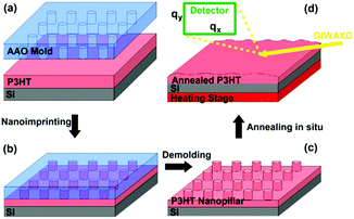 | ||
| Scheme 1 The fabrication and thermal annealing process of the P3HT nanopillar film fabricated by the SART-NIL method. | ||
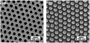
Fig. 1 shows the top-down SEM images of the AAO template and the P3HT nanopillar film. We can see that the AAO template, as shown in Fig. 1a, includes regular and hexagonally packed nanopores bearing a diameter of ∼85 nm and a center-to-center distance (period) of ∼150 nm. The cross-sectional SEM image of the AAO template is shown in Fig. S1 of the ESI† and the length of the nanopores of the AAO template is about 1000 nm. After the AAO template demolded, the diameter and period of the obtained P3HT nanopillars precisely replicate the dimensions of the nanopores within the AAO mold (except for the length of the nanopores due to the limit of the polymer film thickness). This confirms that uniform arrays of the P3HT nanopillars can be obtained by the SART-NIL method. In addition, it is noted that the excellent surface morphology of the P3HT nanopillars indicates that the P3HT molecules are able to flow into and fill the nanopores of the AAO template conveniently during the SART-NIL process. To achieve this goal, the combined action of some factors is a key effect in determining the perfect nanostructure morphology, such as the residual solvent assistance within the polymer film, the stiffness of the AAO template and the applied pressure.
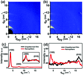
It has been reported that the SART-NIL method is not only able to fabricate the P3HT nanostructures simply but also to adjust the polymer molecule alignment.31,33 To probe the influence of the NIL method on the molecular alignment of the P3HT nanopillars, the crystallization and chain orientation of the P3HT molecule were investigated by grazing incidence wide angle X-ray diffraction (GIWAXD) measurements at a synchrotron radiation facility to provide the beam source. The experimental geometry of the X-ray measurements is shown in Scheme 1d and a two-dimensional charge-coupled device detector is employed to collect the sample image. An incidence angle of 0.18°, above the critical angle of the P3HT polymer (0.16°), was chosen to probe the alignment throughout the entire film.45 Here, we also define the diffraction vector qxy and qz pointing along and normal to the substrate plane, respectively. The peaks at q = 3.8 nm−1 and q = 16.8 nm−1 correspond to the (100) plane and (010) plane reflections of P3HT,31,33 respectively. To illustrate the molecular alignment explicitly and precisely, we simultaneously investigate the two-dimensional (2D) images and one dimensional (1D) GIWAXD intensity profiles of the unpatterned and nanopillar P3HT film, as shown in Fig. 2.
For the unpatterned film, only the (100), (200) and (300) peaks arise along the qz direction, and, simultaneously, only the (010) peak is observed along the qxy direction. Therefore, the unpatterned P3HT film displays an edge-on molecular alignment, in accordance with previously reported results.15,16 However, for the nanoimprinted P3HT nanopillar film, it is indicated that the (100), (200), (300) and (010) peaks emerge along the qz direction, and the (100) and (010) peaks also come up along the qxy direction. Together, there is both edge-on and face-on molecular alignment for the P3HT nanopillar film. Here, the standard crystallographic notation for the P3HT polymer is employed and the two typical edge-on and face-on molecule orientations of the P3HT chain alignment are indicated in Fig. S2 of the ESI.† The lattice parameters a, b and c are pointed out to be the distance between the backbones, the π–π stacking distance and the distance between the side chains, respectively. Therefore, compared to the unpatterned film, this indicates that a face-on molecular orientation is induced in the arrays of the nanopillars, in addition to the edge-on chain alignment. This edge-on chain orientation observed in the nanopillar film arises primarily from the effect of the residual layer beneath the nanopillar structures, in agreement with previous reports.31,33 Compared to the unpatterned film, a face-on molecular orientation is induced in the arrays of the nanopillars and is based on three conclusions reported in our previous works.31,33 Firstly, the limited pressure applied to the samples during the SART-NIL process does not give rise to either the phase transition or the orientation transition from an edge-on to face-on alignment within the unpatterned P3HT thin films.33 Secondly, our previous results indicated that the edge-on molecular alignment dominates in the unpatterned P3HT thin films with various thicknesses.31 Thirdly, the unpatterned film is prepared using the same treatment process as for the nanopillar film, but the face-on molecular orientation is absent in the unpatterned film. Therefore, this proves that the face-on molecular orientation is induced in the P3HT nanopillars. Unfortunately, the portion of the edge-on chain orientation from the nanopillar film cannot be estimated accurately based on the present GIWAXD data. However, it cannot affect the conclusion analysis in this paper because in this paper we aim to investigate the effect of the thermal annealing treatment on the nanostructure morphology and molecular alignment of the nanopillar film. In addition, it is noted that the peak positions of all of the reflections are determined to be steady before and after the SART-NIL process, meaning that there is no change in the crystallographic dimensions of the polymer crystal. However, compared to the peak intensity of the unpatterned film, the intensities of the (010) peak along the qz direction and the (100) peak in the qxy direction are enhanced slightly for the P3HT nanopillar film. On the contrary, the intensities of the (100) peak along the qz direction and the (010) peak in the qxy direction are decreased slightly for the P3HT nanopillar film. This phenomenon of intensity variation may result from the transition of the molecular alignment during the SART-NIL process. Therefore, we demonstrate that the SART-NIL process is able not only to fabricate the topographical nanostructures of the P3HT nanopillar film, but also to induce the molecular alignment transition from edge-on to face-on.
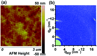
Generally, the stability of both the nanostructure morphology and molecular alignment is very significant for the fundamental study and application of conjugated polymers. It has been reported that thermal annealing was able to affect the stability of both the nanostructure morphology and molecular alignment of conjugated polymers significantly.39,41 Thus, in order to investigate the thermal stability of the P3HT nanopillar film, the effect of the thermal annealing treatment on the nanostructure morphology and molecular alignment of the nanopillar film is studied here in detail. Fig. 3 shows an AFM height image and 2D GIWAXD image of the P3HT nanopillar film after the thermal annealing. The P3HT nanopillar film was annealed under a steady temperature and then was cooled down to room temperature to perform the AFM and GIWAXD measurements. As shown in Fig. 3a, this indicates that the regular surface structure of the P3HT nanopillar film has been changed to become a smooth surface after the thermal annealing. It is noted that the diameter of the deformed P3HT nanopillars after the thermal annealing shifts toward an increased size and the surface is inclined to be flat, although the period of the patterned profile remains to be investigated after applied elevated temperature. Upon the thermal annealing treatment, the polymer is enabled to flow and smooths out to form a flat film surface due to classic surface tension driven viscous flow.35 Thus, finally the thermal annealing treatment process contributes to some collapse of the nanopillar structure. Therefore, the smoothing out of the nanopatterned morphology structure indicates that the imprinted P3HT film shows a rapid decay of the nanostructure profile with increasing temperature.
As shown in Fig. 3b, the 2D diffraction image of the P3HT nanopillar film after the thermal annealing is very similar to that of the nanopatterned film before the thermal annealing (shown in Fig. 2b). The 1D GIWAXD intensity profiles integrated along the qz and qxy directions were also collected for the nanopillar film before and after the thermal annealing, as shown in the ESI (Fig. S3†). This indicates that there is no variance in the number of the reflection peaks. For the P3HT nanopillar film before and after the annealing, the (h00) and (010) reflections both appear in the qz and qxy directions, respectively, indicating that the edge-on alignment is observed due to the existence of a residual layer, and additional reflections of the (010) and (100) planes can also be observed along the qz and qxy directions, respectively, confirming that the induced face-on molecular alignment of P3HT exists in the nanopillars both before and after the annealing. In addition, it is noted that there is a slight fluctuation of the crystallographic dimensions and it can be revealed by the negligible variance of the reflection peak (h00) or (010) positions before and after the annealing. Compared to the nanopillar film before the annealing, the intensities of the diffraction peaks are enhanced slightly after the thermal annealing. This enhancement of the intensity may result from the improved crystallization through a thermal history process. Therefore, the nanoimprinting-induced molecule alignment (face-on orientation) by the SART-NIL process is maintained in the P3HT nanopillars and is not able to be significantly affected by the thermal annealing.
In all, this indicates that the stability of the nanostructure morphology and molecular alignment of the P3HT nanopillar film is different during the thermal annealing. The patterned P3HT film shows a rapid decay of the nanostructure profile at elevated temperature, however, the nanoimprint-induced face-on molecule alignment is retained within the deformed nanostructure morphology. To further reveal the thermal stability process of the nanostructure morphology and molecular alignment of the P3HT nanopillar film in detail, we investigated the evolution of the surface topography of the nanopillar film and the nanoimprinting induced face-on molecule alignment through a continual increasing temperature approach in which the nanopillar film is annealed for a fixed time at a controlled temperature. GIWAXD and AFM measurements in situ were employed to investigate the evolution of the thermal stability.
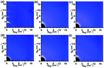
Fig. 4 shows the 2D GIWAXD patterns of the P3HT nanopillar film under the thermal annealing treatment in situ for various temperatures from 23 to 180 °C. To investigate clearly, the 1D integrated intensity profile of the GIWAXD images along the qz and qxy directions was also obtained for the corresponding annealed temperature, as shown in the ESI (Fig. S4†). Compared to the peak intensities of the nanopillar film at 23 °C, the intensities of all of the diffraction peaks of the nanopillar film are reduced successively as the annealing temperature is increased from 23 to 180 °C until the peak intensities become negligible at a temperature of 180 °C. On the contrary, the intensities of all of the peaks are enhanced concomitantly and successively during a temperature decrease from 180 to 80 °C. Therefore, the melt and re-crystallization of the polymer crystal was investigated during the whole annealing process. It is noted that no additional diffraction peak is induced during the annealing process and this can be revealed by the presence of only the (h00) and (010) diffraction planes in the qz or qxy direction. Thus, this indicates that in addition to the edge-on molecule alignment revealed by the (h00) and (010) reflections both appearing in the qz and qxy directions, respectively, the nanoimprint-induced face-on molecule orientation of the P3HT nanopillar film, estimated from the (010) and (100) planes along the qz and qxy directions, respectively, vanishes and next grows concomitantly and successively during the whole thermal annealing process. Therefore, it is concluded that the thermal stability of the molecular alignment of the P3HT nanopillar film is favorable and that the nanoimprint-induced face-on molecule alignment is retained within the deformed nanostructure profile after the thermal annealing.
It is noted that the investigation of the diffraction peaks of the (100) and (010) reflections both in the qxy and qz directions is significantly able to determine the transition of the molecular alignment during the thermal annealing, and thus the magnified details of the (100) and (010) peaks along the qz direction are shown in Fig. S4 of the ESI.† It can be concluded that a feeble fluctuation of the crystallographic structure occurs for the P3HT polymer crystal during the thermal annealing process and it can be revealed by the slight movement of the peak position in the GIWAXD images during the thermal annealing process, as shown in Fig. S3b and c.† As for the (100) peak, the peak position first shifts slightly to a smaller q value and then is improved back during the heating and cooling process. However, as for the (010) peak, the position first moves slightly to a higher q value and then goes back during the annealing process. Of course, the change in the peak position is limited and can be ignored.
It is noted that the higher temperature chosen as 180 °C in this paper is mainly based on two points. One is that the general annealing temperature of conjugated polymers is 180 °C in organic devices and it provides new insight and guidance for understanding the structure–property relationships of organic semiconducting devices. The other is that the intensities of all of the diffraction peaks of the nanopillar film are reduced successively as the annealing temperature increases from 23 to 180 °C until the peak intensities are negligible at a temperature of 180 °C. In addition, we note that a single thermal annealing is not able to affect the molecule alignment transition from the edge-on to face-on alignment and it can be estimated by the thermal stability of the unpatterned P3HT film during the annealing process. The unpatterned P3HT film was employed to carry out the same annealing process as that of the nanopillar film and the corresponding molecule alignment was investigated before and after the annealing, as shown in the ESI (Fig. S5†). This shows that the edge-on molecule alignment, inferred from only the (h00) and (010) reflections existing in the qz and qxy directions, respectively, is still retained before and after the thermal annealing process and no additional diffraction peak is induced during the annealing. Therefore, it can be inferred that a single heating cannot induce the transition of the molecular alignment and the edge-on molecule alignment within the P3HT nanopillar film due to the fact that the residual layer discussed above cannot be induced to the face-on orientation during the annealing process. Thus, the thermal stability of the face-on molecular orientation of the P3HT nanopillar film has nothing to do with the effect of the molecular orientation within the residual layer.
Fig. 5 shows the AFM height images of the P3HT nanopillar film for various temperatures during the thermal annealing process, taken to obtain the detailed structure evolution of the nanograting film surface. As shown in Fig. 5a, the P3HT nanopillar film consists of a regular and hexagonally packed topography nanostructure bearing a period of ∼150 nm, in accordance with the SEM result, as shown in Fig. 1. Here we note that it is difficult to probe the AFM tip during measurement to the bottom of the nanometer spaces between the nanopillars completely due to the lateral resolution of the equipment and thus the height and diameter of the nanopillar structures are indicated to be vague and inaccurate. But this cannot affect the investigation of the stability of the nanopillar profile during the thermal annealing. Therefore, during the annealing at a temperature from 23 to 180 °C, compared with the topography profile at 23 °C, the P3HT nanopillar profile is induced to deform little by little and the diameter of the P3HT nanopillars shifts toward an increased size although the period of the patterned profile remains unchanged. When heating at 180 °C, a relatively uniform and regular nanopillar profile cannot be seen and the surface topography is inclined to become flat. Furthermore, the deformed or similarly smooth surface morphology is still retained when the polymer film is cooled to room temperature. It is noted that the height change of the P3HT nanopillar profile can be investigated during the whole thermal annealing process, but the period of the nanopillars is unchanged after one thermal annealing cycle. Therefore, this indicates that the stability of the nanostructure of the P3HT nanopillars can be affected mainly by the thermal annealing.
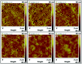 | ||
| Fig. 5 AFM height images of the P3HT nanopillar film for various temperatures during the thermal annealing process: (a) 23 °C, (b) 80 °C, (c) 120 °C, (d) 140 °C, (e) 180 °C, and (f) 23 °C. | ||
Therefore, this confirms that the thermal annealing plays a different role in the stability of the nanostructure morphology and molecular alignment of the P3HT nanopillar film. The stability of the patterned nanopillar profile significantly depends on the thermal annealing temperature, however, the stability of the nanoimprint-induced face-on molecule alignment is not dependent on the annealing temperature, as shown in Fig. 6. As a matter of fact, the stability of the P3HT nanopillar profile under the thermal annealing is mainly determined by the surface tension or internal stress.35 The deformation of the nanopillar structures can be investigated due to the increase of the tension or internal stress induced by the heating energy. Thus, this finally leads to the deformation or collapse of the P3HT nanopillar profile at elevated temperature. The effect of the heating temperature from 23 to 180 °C demonstrates that the crystal of the face-on molecular orientation is melted gradually until the completion of the melt. As the temperature is decreased from 180 to 23 °C, the nucleation and growth of the face-on crystal during the crystallization process are improved from the polymer melt. Finally, the face-on molecular orientation before annealing is retained in the deformed or collapsed P3HT nanopillar film. Therefore, this indicates a stability of the molecular alignment and an instability of the nanostructure morphology during the whole annealing process. As discussed above, this demonstrates that the SART-NIL technique is not only used to fabricate the nanostructure but also induces a face-on molecular alignment in the arrays of the nanopillar nanostructures. It can be inferred that there is a close connection between them. However, the transition of the nanostructure and alignment is different during the annealing process. Thus, it can be inferred further that there is no direct interconnection between them during the annealing or that the stability of the morphology and alignment is significantly different. A comprehensive understanding of the stability difference between the alignment and morphology during the annealing is unknown for now, however, it can be concluded that annealing is a powerful tool for controlling both the nanostructure and molecular alignment in polymer materials and it should provide new insight and guidance for understanding the structure–property relationships of organic semiconducting devices.
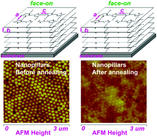 | ||
| Fig. 6 Schematic images of the stability of the nanostructure morphology and molecular alignment for the P3HT nanopillar film during the thermal annealing. | ||
Here, the P3HT nanopillar film can be fabricated by this SART-NIL method and the face-on molecular alignment is induced in the arrays of the nanopillar nanostructures. Furthermore, thermal annealing plays a different role in the stability of the nanostructure morphology and molecular alignment for the P3HT nanopillar film. That is, the stability of the patterned nanopillar profile depends significantly on the annealing temperature, however, the nanoimprint-induced face-on molecule alignment is maintained after the thermal annealing. In our previous report,46 we reported that the nanograting topography of the P3HT film can also be excellently fabricated by the SART-NIL method and the molecular orientation transition from the edge-on to face-on alignment was confirmed in the nanograting P3HT film. This indicated that the highly well-ordered nanostructure morphology of the nanograting film nearly vanished at elevated annealing temperature, however, the nanoimprint-induced face-on molecule orientation remained constant within the distorted nanograting film. Thus, this indicates that the conclusion seems to be similar in the two papers. Of course, the most significant difference is that two different molds were used in these two works, that is, the silicon mold for the P3HT nanogratings and the AAO mold for the nanopillars, however, the significance inferred from the two different molds is various. First, the two typical nanostructure profiles of the conjugated polymers are the nanogratings and nanopillars, thus it is necessary to focus on the thermal stability of the profiles and molecular orientations of the nanogratings and nanopillars for the integrality study of conjugated polymer applications. Second, the induced face-on orientation stems from the different confined space due to the different nanostructure dimensions, thus it is significant to investigate the thermal stability process of the molecular orientation for the nanogratings and nanopillars. Third, the deformed processing of the nanoprofile due to the different dimensions is various between the nanogratings and nanopillars, therefore, the investigation of different deformed processing is a powerful tool for controlling both the nanostructures and molecular alignment in polymer materials and provides new insight and guidance for understanding the structure–property relationships of organic semiconducting devices. In all, there is a strong internal connection between these two works but an obvious difference is still present.
Conclusions
In all, we demonstrate here that the fabrication of a patterned P3HT nanopillar film can be achieved by this simple and cost-effective SART-NIL technique. To probe the influence of the NIL method on the molecular alignment of the P3HT nanopillars, the crystallization and chain orientation of the P3HT nanopillar film were investigated by GIWAXD measurements at a synchrotron radiation facility to provide the beam source. The result indicates that face-on molecular orientation is induced in the arrays of the nanopillar film. In order to investigate the thermal stability of the P3HT nanopillar film, the effect of the thermal annealing treatment on the nanostructure morphology and molecular alignment of the nanopillar film was studied. The stability of the nanostructure morphology and molecular alignment of the P3HT nanopillar film is different during the thermal annealing. The patterned P3HT film shows a rapid decay of the nanostructure profile at elevated temperature, however, the nanoimprint-induced face-on molecule alignment is retained within the deformed nanostructure morphology. In addition, the evolution of the surface topography and the molecule alignment was also investigated in detail during the thermal annealing. The results will contribute to providing new insight and guidance for the fabrication of topographical nanostructures and the molecular orientation of conjugated polymers.Conflicts of interest
There are no conflicts to declare.Acknowledgements
This work is financially supported by the National Natural Science Foundation of China (No. 21504028), Natural Science Foundation of the Educational Committee of Anhui Province (KJ2015A119), Innovation Team of Design and Application of Advanced Energetic Materials and the Collaborative Innovation Center of Advanced Functional Composites in Anhui Province. The authors also thank beamline BL14B1 (Shanghai Synchrotron Radiation Facility) for providing beam time and help during experiments.Notes and references
- R. H. Friend, R. W. Gymer, A. B. Holmes, J. H. Burroughes, R. N. Marks, C. Taliani, D. D. C. Bradley, D. A. Dos Santos, J. L. Bredas, M. Logdlund and W. R. Salaneck, Nature, 1999, 397, 121–128 CrossRef CAS.
- H. Xuan, X. Chen, Y. Wu, K. Song, Y. Li and R. Liu, RSC Adv., 2016, 6, 15577–15584 RSC.
- D. Gebeyehu, C. J. Brabec, F. Padinger, T. Fromherz, J. C. Hummelen, D. Badt, H. Schindler and S. N. Sariciftci, Synth. Met., 2001, 118, 1–9 CrossRef CAS.
- M. Siclair, D. Moses, K. Akagi and A. J. Heeger, Phys. Rev. B: Condens. Matter Mater. Phys., 1988, 38(15), 10724–10733 CrossRef.
- H. Sirringhaus, P. J. Brown, R. H. Friend, M. M. Nielsen, K. Bechgaard, B. M. W. Langeveld Voss, A. J. H. Spiering, R. A. J. Janssen, E. W. Meijer, P. Herwig and D. M. De Leeuw, Nature, 1999, 401, 685–688 CrossRef CAS.
- H. Sirringhaus, R. J. Wilson, R. H. Friend, M. Inbasekaran, W. Wu, E. P. Woo, M. Grell and D. D. C. Bradley, Appl. Phys. Lett., 2000, 77, 406–408 CrossRef CAS.
- R. J. Kline, M. D. Mcgehee and M. F. Toney, Nat. Mater., 2006, 5, 222–228 CrossRef.
- T. Erb, U. Zhokhavets, G. Gobsh, S. Raleva, B. Stuhn, P. Schilinsky, C. Waldauf and C. J. Brabec, Adv. Funct. Mater., 2005, 15, 1193–1196 CrossRef CAS.
- J. H. Lee, D. W. Kim, H. Jang, J. K. Choi, J. X. Geng, J. W. Jung, S. C. Yoon and H. T. Jung, Small, 2009, 5, 2139–2143 CrossRef CAS PubMed.
- Y. Yang, K. Mielczarek, M. Aryal, A. Zakhidov and W. Hu, ACS Nano, 2012, 6, 2877–2892 CrossRef CAS PubMed.
- B. Yang, M. Xiao, C. Zhao, S. Zhang, A. Jiang and J. Wang, Small, 2012, 8, 2021–2026 CrossRef CAS PubMed.
- H. Yang, S. W. Lefevre, C. Y. Ryu and Z. N. Bao, Appl. Phys. Lett., 2007, 90, 172116 CrossRef.
- Z. Zheng, K. H. Yim, M. S. M. Saifullah, M. E. Welland, R. H. Friend, J. S. Kim and W. T. S. Huck, Nano Lett., 2007, 7, 987–992 CrossRef CAS PubMed.
- Z. Hu, B. Muls, L. Gence, D. A. Serban, J. Hofkens, S. Melinte, B. Nysten, S. Demoustier-Champagne and A. M. Jonas, Nano Lett., 2007, 7, 3639–3644 CrossRef CAS PubMed.
- M. Aryal, K. Trivedi and W. C. Hu, ACS Nano, 2009, 3, 3085–3090 CrossRef CAS PubMed.
- H. Hlaing, X. Lu, T. Hofmann, K. G. Yager, C. T. Black and B. M. Ocko, ACS Nano, 2011, 5, 7532–7538 CrossRef CAS PubMed.
- Z. Hu, M. Tian, B. Nysten and A. M. Jonas, Nat. Mater., 2009, 8, 62–67 CrossRef CAS PubMed.
- Z. Hu and A. M. Jonas, Soft Matter, 2010, 6, 21–28 RSC.
- B. C. Okerberg, C. L. Soles, J. F. Douglas, H. W. Ro, A. Karim and D. R. Hines, Macromolecules, 2007, 40, 2968–2970 CrossRef CAS.
- S. Kim, J. Lee, S. Jeon, H. H. Lee, K. Char and B. Sohn, Macromolecules, 2008, 41, 3401–3404 CrossRef CAS.
- J. Cheng, C. A. Ross, H. I. Smith and E. L. Thomas, Adv. Mater., 2006, 18, 2505–2521 CrossRef CAS.
- P. Thebault, S. Niedermayer, S. Landis, N. Chaix, P. Guenoun, J. Daillant, X. Man, D. Andelman and H. Orland, Adv. Mater., 2012, 24, 1952–1955 CrossRef PubMed.
- L. J. Guo, Adv. Mater., 2007, 19, 495–513 CrossRef CAS.
- M. Behl, J. Seekamp, S. Zankovych, C. M. Sotomayor Torres, R. Zentel and J. Ahopelto, Adv. Mater., 2002, 14, 588–591 CrossRef CAS.
- F. Di Benedetto, A. Camposeo, S. Pagliara, E. Mele, L. Persano, R. Stabile, R. Cingolani and D. Pisignano, Nat. Nanotechnol., 2008, 3, 614–619 CrossRef CAS PubMed.
- M.-S. Kim, J.-S. Kim, J. C. Cho, M. Shtein, L. J. Guo and J. Kim, Appl. Phys. Lett., 2007, 90, 123113–123116 CrossRef.
- E. Mele, F. Di Benedetto, L. Persano, R. Cingolani and D. Pisignano, Nano Lett., 2005, 5, 1915–1919 CrossRef CAS PubMed.
- N. E. Voicu, S. Ludwigs, E. J. W. Crossland, P. Andrew and U. Steiner, Adv. Mater., 2007, 19, 757–761 CrossRef CAS.
- X. He, F. Gao, G. Tu, D. G. Hasko, S. Huttner, N. C. Greenham, U. Steiner, R. H. Friend and W. T. S. Huck, Adv. Funct. Mater., 2011, 21, 139–146 CrossRef CAS.
- G. Ding, K. Wang, X. Li, Q. Chen, Z. Hu and J. Liu, Nanoscale Res. Lett., 2016, 11, 258 CrossRef PubMed.
- G. Ding, C. Li, X. Li, Y. Wu, J. Liu, Y. Li, Z. Hu and Y. Li, Nanoscale, 2015, 7, 11024–11032 RSC.
- G. Ding, Q. Jin, Q. Chen, Z. Hu and J. Liu, Nanoscale Res. Lett., 2015, 10, 491 CrossRef PubMed.
- D. Ding, Y. Wu, Y. Weng, W. Zhang and Z. Hu, Macromolecules, 2013, 46, 8638–8643 CrossRef.
- Y. Ding, H. W. Ro, K. J. Alvine, B. C. Okerberg, J. Zhou, J. F. Douglas, A. Karim and C. L. Soles, Adv. Funct. Mater., 2008, 18, 1854–1862 CrossRef CAS.
- Y. Ding, H. J. Qi, K. J. Alvine, H. W. Ro, D. U. Ahn, S. Lin-Gibson, J. F. Douglas and C. L. Soles, Macromolecules, 2010, 43, 8191–8201 CrossRef CAS.
- T. Leveder, S. Landis, L. Davoust and N. Chaix, Microelectron. Eng., 2007, 84, 953 CrossRef CAS.
- J. S. Kim, Y. Park, D. Y. Lee, J. H. Lee, J. H. Park, J. K. Kim and K. Cho, Adv. Funct. Mater., 2010, 20, 540–545 CrossRef CAS.
- S. Moungthai, N. Mahadevapuram, P. Ruchhoeft and G. E. Stein, ACS Appl. Mater. Interfaces, 2012, 4(8), 4015–4023 CAS.
- S. Dunst, T. Rath, A. Radivo and G. Trimmel, ACS Appl. Mater. Interfaces, 2014, 6(10), 7633–7642 CAS.
- E. Verploegen, R. Mondal, C. J. Bettinger, S. Sok, M. F. Toney and Z. Bao, Adv. Funct. Mater., 2010, 20, 3519–3529 CrossRef CAS.
- K. A. Smith, Y. Lin, J. W. Mok, K. G. Yager, J. Strzalka, W. Nie, A. D. Mohite and R. Verduzco, Macromolecules, 2015, 48, 8346–8353 CrossRef CAS.
- S. Himmelberger, J. Dacuna, J. Rivnay, L. H. Jimison, T. Mccarthy-Ward, M. Heeney, L. Mcculloch, M. F. Toney and A. Salleo, Adv. Funct. Mater., 2013, 23, 2091–2098 CrossRef CAS.
- Y. Wu, Q. Gu, G. Ding, F. Tong, Z. Hu and A. M. Jonas, ACS Macro Lett., 2013, 2, 535–538 CrossRef CAS.
- T. Yang, W. Wen and G. Yin, et al., Nucl. Sci. Technol., 2015, 26, 020101 Search PubMed.
- D. Chen, W. Zhao and T. P. Russell, ACS Nano, 2012, 6, 1479–1485 CrossRef CAS PubMed.
- G. Ding, K. Wang, X. Li, C. Wang, Z. Hu and J. Liu, Polym. Chem., 2017, 8, 2666–2674 RSC.
Footnote |
| † Electronic supplementary information (ESI) available. See DOI: 10.1039/c7ra09667d |
| This journal is © The Royal Society of Chemistry 2017 |

