DOI:
10.1039/C7RA09665H
(Paper)
RSC Adv., 2017,
7, 55020-55025
A magnetic CoFe2O4–CNS nanocomposite as an efficient, recyclable catalyst for peroxymonosulfate activation and pollutant degradation†
Received
31st August 2017
, Accepted 27th November 2017
First published on 4th December 2017
Abstract
Sulfate radical (SO4˙−) based advanced oxidation processes allow efficient degradation of refractory organics, but efficient, low-cost, and robust catalysts for such processes are still lacking. In this work, a magnetically recoverable heterogeneous catalyst was fabricated by immobilizing spinel cobalt-ferrite (CoFe2O4) particles on graphitic carbon nitride nanosheets (CNS) using a low-cost, one-step solvothermal method. In the CoFe2O4–CNS nanocomposite, the CoFe2O4 particles were evenly-distributed on the CNS surface, giving the nanocomposite a high specific surface area and significantly raised activity for peroxymonosulfate (PMS) activation and sulfonamide degradation compared to the bare CoFe2O4 NPs, which were considerably aggregated. In addition, the CoFe2O4–CNS could be more efficiently separated under magnetic field and resuspended compared with the bare CoFe2O4 due its larger sizes and no agglomeration. A stable activity of the nanocomposite catalyst during repeated use was also demonstrated. Our results imply high potential of CoFe2O4–CNS for sustainable water treatment and environmental remediation applications.
1. Introduction
Advanced oxidation processes (AOP) based on the sulfate radical (SO4˙−) are promising alternatives to those based on hydroxyl radicals for water treatment and environmental remediation applications, with advantages such as high redox potential (2.5–3.1 V),1 relatively long lifetime and wide pH range.2 SO4˙− can be efficiently generated from peroxymonosulfate (PMS)3 or persulfate (PS)4,5 by using transition metals as catalysts. Cobalt (Co)-based materials are the most efficient catalysts for PMS activation so far.6,7 In particular, heterogeneous Co catalysts are gaining growing interest because they can be reused and are environmentally-benign.8–10 To facilitate their recovery after use, spinel-type Co-bearing ferrite nanoparticles (CoFe2O4 NPs) have been recently developed, which show high catalytic activity and good adaptability to magnetic separation.11 However, such nanoparticles are difficult to magnetically separate from the water phase due to their small sizes.12,13 Another challenge is the easy agglomeration of the NPs, which leads to poor re-suspension and reduced performance with repeated use.11 One strategy to address the NPs separation and agglomeration issue is to disperse the NPs on various support materials, including reduced graphene oxide (rGO),14 carbon nanotube,15 titanate nanotubes.16,17 Recently, the combination of CoFe2O4 with graphitic carbon nitride (g-C3N4, a low-cost, highly-stable, and porous 2D materials with unique photocatalytic activity18–21) has also been proposed. The CoFe2O4/g-C3N4 showed high photocatalytic activity for degradation Rhodamine B,22,23 but has not been used for SO4˙−-based AOP so far. In addition, the synthesis process of the composite (involving precipitation, ultrasonic mixing and calcining) is complicated, and bulk g-C3N4 (ref. 22 and 23) with large size and low specific surface area was typically used.24,25
Inspired by the above studies, here we investigated the feasibility of using CoFe2O4/g-C3N4 as a catalyst for activation of PMS. To improve its catalysis and recovery performances, we adopted a simple, one-step solvothermal method for the material fabrication, and used ultrathin g-C3N4 nanosheet (CNS) as the support for CoFe2O4.18 The catalytic activities of the resulting CoFe2O4–CNS nanocomposite and the CoFe2O4/g-C3N4 obtained by conventional method were evaluated by using sulfonamide (SA) as a model pollutant. SA is a ubiquitous, persistent contaminant, with high risks to aquatic ecosystem and human health.26–30 In addition, SA is a rich-electronic compound, which is suitable for SO4˙−-based AOP.3,31,32 The magnetic separation and re-suspension performances and the stability of the materials during repeated use were also investigated. Lastly, the catalytic mechanisms of the nanocomposite for PMS activation were elucidated.
2. Experimental
2.1. Materials
Iron chloride (FeCl3·6H2O), cobalt dichloride (CoCl2·6H2O), sodium acetate (NaAc), and ethylene glycol, ethanol, melamine, sulfanilamide, methanol, tert-butyl alcohol (TBA), all of analytical grade, were purchased from Sinapharm Chemical Reagent Co., Ltd. Peroxymonosulfate (PMS, Oxone) was purchased from J&K Scientific LTD. All the solutions were prepared with deionized (DI) water.
2.2. Synthesis of CoFe2O4–CNS catalyst
The CNS were synthesized according to the method described in a previous report.21 Melamine (5 g) was calcined at 520 °C for 4 h with the heating rate of 5 °C min−1 to obtain yellow bulk g-C3N4. Then, the bulk g-C3N4 was milled into powder, transferred into a combustion boat without any cover, and heated at 550 °C for 3 h to obtain CNS. The resulting CNS (200 mg) was added into 30 mL ethylene glycol solution under ultrasonication, followed by adding 2 mmol FeCl3·6H2O and 1 mmol CoCl2·6H2O. Then, 15 mmol sodium acetate, as a protective agent to control the shape of synthesized nanomaterials, was added into the solution under vigorous stirring at room temperature. The mixture was subsequently autoclaved in a 50 mL Teflon lined stainless steel autoclave at 180 °C for 24 h, and then naturally cooled down to room temperature. The resulting black precipitate was collected by filtration and washed with absolute ethanol and DI water in sequence for several times. The final product was dried in a vacuum box at 60 °C for 6 h prior to use. For comparison, the bare CoFe2O4 was fabricated without the addition of g-C3N4 following the same procedures.33,34 In addition, graphene oxide-supported CoFe2O4 (CoFe2O4–GO) was prepared following a reported method.35
2.3. Catalytic activity test
The catalytic activities of different materials for PMS activation and SA degradation was examined. The bare CoFe2O4 NPs and g-C3N4 were used as the controls. Before the degradation test, SA was added into 100 mL DI water under constant stirring to an initial concentration of 10 mg L−1. Then, 100 mg L−1 catalyst and 100 mg L−1 PMS were added to initiate the degradation reactions. During the test, 1 mL mixed liquor was collected each time at given time intervals, immediately quenched with excess pure methanol (1 mL), and then centrifuged before analysis. All the experiment was conducted in duplicate at ambient temperature (25 ± 2 °C).
2.4. Analysis
The SA concentration was measured by a liquid chromatograph (Alliance, water 2695) equipped with Waters 2487 dual λ absorbance detector and Agilent 5 TC-C18 150 × 4.6 mm column. A mixture of methanol and 0.1% formic acid solution (20![[thin space (1/6-em)]](https://www.rsc.org/images/entities/char_2009.gif) :
:![[thin space (1/6-em)]](https://www.rsc.org/images/entities/char_2009.gif) 80, v/v) at a flow rate of 0.5 mL min−1 was used as the mobile phase. The column temperature was 30 °C. The detection wavelength was set at 268 nm.
80, v/v) at a flow rate of 0.5 mL min−1 was used as the mobile phase. The column temperature was 30 °C. The detection wavelength was set at 268 nm.
The morphology and structure of the materials were examined by scanning electron microscopy (SEM, QUSNTA FEG 250) and transmission electronic microscopy (TEM, HT7700). X-ray diffraction (XRD) patterns were obtained on a Bruker D8 diffractometer using filtered Cu Kα radiation (α = 1.54178 Å). The Brunauer–Emmett–Teller (BET) specific surface area of sample was determined on an Autosorb iQ Station 3 system at liquid-nitrogen temperature of 77.35 K. The chemical species of Co, Fe, O, C and N were determined by X-ray photoelectron spectroscopy (XPS). Magnetic properties of the samples were examined using a MPMS (SQUID)-vibrating sample magnetometer at 300 K.
3. Results
3.1. Catalysts characterization
The morphologies of the CNS, bare CoFe2O4 and CoFe2O4–CNS composite are shown in Fig. 1. The CNS had large sizes ranging from hundreds of nanometer to several micrometer (Fig. 1(a)) but a small thickness of around 10 nm (Fig. 1(d)). The bare CoFe2O4 was mainly in the shape of spherical particles that aggregated together (Fig. 1(b) and (e)). In comparison, for the CoFe2O4–CNS composites, the particles were evenly distributed on the CNS (Fig. 1(c) and (f)). The particles did not peel off from the CNS after ultrasonic processing for 30 min due to the formation of heterostructured material. The high resolution TEM (HRTEM) image of CoFe2O4–CNS showed lattice fringe spacing of 0.24 nm, 0.25 nm, 0.29 nm and 0.487 nm (Fig. 1(g) and (h)), consistent with the (2 2 2) (3 1 1) (2 2 0) and (1 1 1) planes of CoFe2O4 crystals, respectively.36,37 No clear lattice was observed for the CNS due to its low crystallinity. The two components were tightly bonded together, as indicated by the clear interface between them. In addition, the EDX spectra confirm the presence of Co, Fe, C, O, and N elements in the CoFe2O4–CNS (Fig. 1(i)). The Si signal observed here was derived from the silicon substrate.
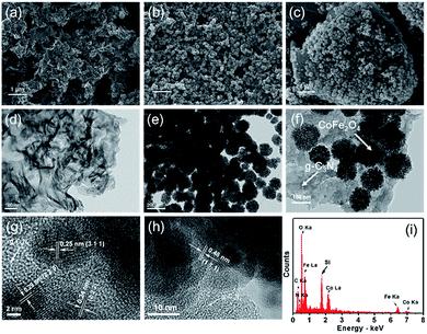 |
| | Fig. 1 SEM (a–c) and TEM (d–f) images of (a and d) g-C3N4, (b and e) bare CoFe2O4, (c and f) CoFe2O4–CNS; (g and h) HRTEM images and (i) EDX pattern of CoFe2O4–CNS. | |
The synthesis of the CoFe2O4 and CoFe2O4–CNS composites was also confirmed by the XRD and XPS spectra. The CoFe2O4 showed a typical pattern of spinel ferrite with six well-defined peaks at 2θ = 18.29°, 30.08°, 35.44°, 43.06°, 56.97°, and 62.58° (Fig. 2(a)), corresponding to the Bragg planes of (1 1 1), (2 2 0), (3 1 1), (4 0 0), (5 1 1), and (4 4 0), respectively.38,39 The major crystal phase of CoFe2O4 was in a good agreement with JCPDS: 22-1086. For the CoFe2O4–CNS, besides the above six peaks, a characteristic peak at 27.6° corresponding to the (0 0 2) diffraction plane of the CNS was also detected, and no other peaks occurred (Fig. S1†). These results indicate a high purity of the synthesized products. In addition, the XPS survey scan spectra of both materials showed the characteristic peaks of Co, Fe and O, and the extra signal of C (284 eV) and N (400 eV) in the CoFe2O4–CNS, further confirming the formation of CoFe2O4 and CoFe2O4–CNS with high purity (Fig. 2(b)).
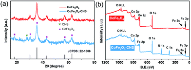 |
| | Fig. 2 (a) XRD patterns of CoFe2O4 and CoFe2O4–CNS, (b) XPS survey spectra of CoFe2O4 and CoFe2O4–CNS. | |
The surface properties of the synthesized materials were also evaluated. Despite of the similar ordered mesoporous structure and pore sizes of the two materials (Fig. 3), the CoFe2O4–CNS had larger specific surface area (89.484 m2 g−1 versus 81.253 m2 g−1) and larger pore volume (0.163 cm3 g−1 versus 0.108 cm3 g−1) than CoFe2O4.
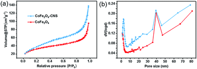 |
| | Fig. 3 (a) Nitrogen sorption isotherms and (b) pore size distribution of CoFe2O4 and CoFe2O4–CNS. | |
3.2. Catalytic activity for SO4˙− generation and SA degradation
The CoFe2O4–CNS showed significantly higher activity for PMS activation and SA degradation than the CoFe2O4 NPs (Fig. 4(a)) and the CoFe2O4–GO (Fig. S2(a)†). Consistent result was also obtained by the TOC analysis (Fig. 4(b)). In light of the negligible SA removal in the PMS- or catalyst-free controls, this result also implies the critical involvement of SO4˙− in the process. Here, the higher catalytic activity of CoFe2O4–CNS than CoFe2O4–GO is likely associated with a better dispersion of the CoFe2O4 on the CNS with large surface area (Fig. S2(b)†).
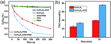 |
| | Fig. 4 (a) Removal of SA in different processes. (b) TOC removal of SA at different reaction times. Reaction conditions: [SA] = 10 mg L−1, [PMS] = 0.10 g L−1, [catalyst] = 0.10 g L−1. | |
The predominant contribution of SO4˙− to the SA degradation in the CoFe2O4–CNS/PMS system was further confirmed by radicals quenching tests using ethanol or tert-butyl alcohol (TBA) as the quencher.40 Ethanol is commonly used as a scavenger to quickly react with both hydroxyl and sulfate radical species, whereas TBA mainly quenches OH˙.41 Our results show that the SA degradation was almost completely inhibited in the presence of excess ethanol (Fig. 5(a)), but was decreased only by 22% (within 5 min) with TBA addition. Therefore, the key role of SO4˙− in the SA degradation can be confirmed.
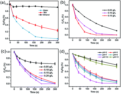 |
| | Fig. 5 (a) Effects of radical scavengers on SA degradation in the CoFe2O4–CNS/PMS system. SA removal efficiencies under different reaction conditions: (b) different catalyst dosage, initial pH = 6.3, [SA] = 10 mg L−1, [PMS] = 0.10 g L−1. (c) Effect of PMS concentration, initial pH = 6.3, [SA] = 10 mg L−1, [catalyst] = 0.10 g L−1. (d) Effect of initial pH, [SA] = 10 mg L−1, [PMS] = 0.10 g L−1, [catalyst] = 0.10 g L−1. | |
The SA degradation performances varied under different catalyst dosage, PMS dosage, and the initial pH conditions. The SA removal increased markedly with catalyst dosage from 0.05 to 0.1 g L−1, but increased only slightly when further increasing catalyst dosage to 0.15 g L−1 (Fig. 5(b)), indicating that 0.1 g L−1 catalyst is sufficient in our reaction system. Increasing PMS concentration also significantly raised the SA removal initially but the removal ratio became relatively stable at high PMS dosage (Fig. 5(c)), likely resulting from self-quenching of the generated SO4˙− by excess PMS.42 In addition, the catalyst showed stable activity over a wide pH range of 5–10 (Fig. 5(d)). The best performance at initial pH of 10.0 was consistent with previous studies.43 Here, the significant performance decline at pH 11.0 might be due to a competitive conversion of PMS to less-active dianion (SO52−) and OH˙ under alkaline condition44 and increased electrostatic compelling between the negatively-charged catalyst and PMS species,41 whereas the suppression at pH 3.0 should be associated with the deactivation of catalyst with protonation of the surface hydroxyl groups.3
| | |
Co2+ + H2O → CoOH+ + H+
| (1) |
3.3. Magnetic separation and reuse performances
The magnetic properties of the CoFe2O4 and CoFe2O4–CNS composites were evaluated, and the magnetic hysteresis loops are shown in Fig. 6. The CoFe2O4–CNS showed a lower saturation magnetization value (Ms = 56.1 emu g−1) than CoFe2O4 (Ms = 88.7 emu g−1), which should be due to magnetic property dilution by the nonmagnetic CNS component.
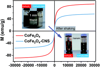 |
| | Fig. 6 Magnetic hysteresis loops of CoFe2O4 and CoFe2O4–CNS composites at room temperature. Inset: separation and resuspension performance of the synthesized materials. | |
Nevertheless, the CoFe2O4 was more difficult to be attracted by the magnet, due to smaller sizes of the particles (average size 176 nm for CoFe2O4 versus 1.38 μm for CoFe2O4–CNS) (Fig. S3†). According to the literature,12,13,45 the smaller nanoparticles are more difficult to recover than larger ones under magnetic field. Therefore, a more effective, rapid magnetical separation of CoFe2O4–CNS than CoFe2O4 was achieved in our study (Fig. 6 Inset). Furthermore, for the small-sized CoFe2O4 particles, an agglomeration would occur during their magnetic separation, and the resulting aggregates are difficult to re-disperse even with intense ultrasonication.13,46 This explains the much poorer re-suspension of CoFe2O4 than the larger-sized yet well-dispersed CoFe2O4–CNS (Fig. 6 Inset).
The CoFe2O4–CNS also showed good stability during repeated use. After five successive reaction cycles, the system still maintained 94.8% SA removal within 30 min (Fig. S4†). In comparison, the SA removal ratio was 98.6% for the CoFe2O4 in first cycle and gradually decreased to 69.5% by the fifth cycle (Fig. S4†). The leaching of Co(II) was also more serious in CoFe2O4 (Fig. S5†). These result indicate a good repeatability and robustness of the CoFe2O4–CNS far exceeding existing CoFe2O4 catalysts.
3.4. Mechanism of PMS activation by CoFe2O4–CNS
The XPS spectra of CoFe2O4–CNS and CoFe2O4 before and after reaction were measured to show the possible changes of the catalysts. The high resolution XPS spectra of the Co 2p3/2 show three peaks at 779.9, 781.2 and 782.8 eV for all the samples (Fig. 7). These peaks were attributed to the CoII in octahedral (B-site CoII) and tetrahedral sites (A-site CoII) and CoIII in tetrahedral (B-site CoIII), respectively. It is suggested that during the catalysis the B-site CoII would provide electrons to PMS, leading to SO4˙− production and increase of CoIII in B-site (eqn (2)). The latter can also accept electrons from PMS to regenerate CoII with concomitant production of SO5˙− (eqn (3)), thus maintaining the CoII–CoIII–CoII redox cycles for the continuous catalysis.11,47,48 Our results show that the proportion of B-site CoII in CoFe2O4–CNS slightly decreased from 58% to 50% after reaction, while B-site CoII in CoFe2O4 drastically decreased from 63% to 32%. Accordingly, the CoIII in tetrahedral of CoFe2O4–CNS showed less increase (11%) than that of CoFe2O4 (17%), indicating a more efficient regeneration of B-site CoII in CoFe2O4–CNS. In addition, the high resolution XPS spectra of Fe 2p (Fig. S6†) showed two major peaks assigned to FeII (710.6 eV) and FeIII (712.6 eV). The catalytic activity of the FeII/FeIII redox pair (eqn (4) and (5)) for PMS activation has been demonstrated previously.11,14,48,49 The CoFe2O4–CNS showed less decrease in FeII content than CoFe2O4 after the reaction. Such an improved FeII regeneration also contributed to the better sustained activity of CoFe2O4–CNS in repeated use.
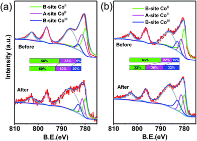 |
| | Fig. 7 XPS of Co 2p spectra of (a) CoFe2O4–CNS composites and (b) CoFe2O4 before and after the reaction with PMS. | |
High resolution N 1s spectra (Fig. S7a†) could be fitted into three peaks at 399.1 eV (C–N![[double bond, length as m-dash]](https://www.rsc.org/images/entities/char_e001.gif) C groups, denoted as N1), 399.9 eV (amino groups ((C)2–N–H) connecting with structural defects and incomplete condensation, denoted as N2), 401.2 eV (N–(C)3 in the aromatic ring, denoted as N3). For the CoFe2O4–CNS, the intensity of N1 peak decreased by 2% after the reaction while that of N2 peak increased by 2%. The g-C3N4 contains abundant graphitic N corresponding to the sp2-bonded N that are involved in the triazine rings (N1)50 and can induce electron transfer from adjacent carbon atoms to nitrogen. Such a feature renders the sp2 carbon layer of the g-C3N4 a high chemical activity.51–54 Therefore, it is possible that the delocalized electrons from grapheme N on the zigzag edges of CNS might also contributed to the reduction of MIII (M = Co or Fe) species, thus the C–N
C groups, denoted as N1), 399.9 eV (amino groups ((C)2–N–H) connecting with structural defects and incomplete condensation, denoted as N2), 401.2 eV (N–(C)3 in the aromatic ring, denoted as N3). For the CoFe2O4–CNS, the intensity of N1 peak decreased by 2% after the reaction while that of N2 peak increased by 2%. The g-C3N4 contains abundant graphitic N corresponding to the sp2-bonded N that are involved in the triazine rings (N1)50 and can induce electron transfer from adjacent carbon atoms to nitrogen. Such a feature renders the sp2 carbon layer of the g-C3N4 a high chemical activity.51–54 Therefore, it is possible that the delocalized electrons from grapheme N on the zigzag edges of CNS might also contributed to the reduction of MIII (M = Co or Fe) species, thus the C–N![[double bond, length as m-dash]](https://www.rsc.org/images/entities/char_e001.gif) C groups would be disrupted to form –NH2 or –NH groups (eqn (6) and (7)) (Fig. S7(c)†). This was verified by the FT-IR spectra of CoFe2O4–CNS which showed increased –NH2 or –NH groups (absorption centred at 3184 cm−1)17 and decreased C–N
C groups would be disrupted to form –NH2 or –NH groups (eqn (6) and (7)) (Fig. S7(c)†). This was verified by the FT-IR spectra of CoFe2O4–CNS which showed increased –NH2 or –NH groups (absorption centred at 3184 cm−1)17 and decreased C–N![[double bond, length as m-dash]](https://www.rsc.org/images/entities/char_e001.gif) C groups after the reaction (Fig. S7(b)†).
C groups after the reaction (Fig. S7(b)†).
| |
![[triple bond, length as m-dash]](https://www.rsc.org/images/entities/char_e002.gif) CoII + HSO5− → CoII + HSO5− → ![[triple bond, length as m-dash]](https://www.rsc.org/images/entities/char_e002.gif) CoIII + SO4˙− + OH− CoIII + SO4˙− + OH−
| (2) |
| |
![[triple bond, length as m-dash]](https://www.rsc.org/images/entities/char_e002.gif) CoIII + HSO5− → CoIII + HSO5− → ![[triple bond, length as m-dash]](https://www.rsc.org/images/entities/char_e002.gif) CoII + SO5˙− + H+ CoII + SO5˙− + H+
| (3) |
| |
![[triple bond, length as m-dash]](https://www.rsc.org/images/entities/char_e002.gif) FeII + HSO5− → FeII + HSO5− → ![[triple bond, length as m-dash]](https://www.rsc.org/images/entities/char_e002.gif) FeIII + SO4˙− + OH− FeIII + SO4˙− + OH−
| (4) |
| |
![[triple bond, length as m-dash]](https://www.rsc.org/images/entities/char_e002.gif) FeIII + HSO5− → FeIII + HSO5− → ![[triple bond, length as m-dash]](https://www.rsc.org/images/entities/char_e002.gif) FeIII + SO5˙− + H+ FeIII + SO5˙− + H+
| (5) |
| |
![[triple bond, length as m-dash]](https://www.rsc.org/images/entities/char_e002.gif) CoIII + e(C–N CoIII + e(C–N![[double bond, length as m-dash]](https://www.rsc.org/images/entities/char_e001.gif) C)− → C)− → ![[triple bond, length as m-dash]](https://www.rsc.org/images/entities/char_e002.gif) CoII + –NH2/–NH CoII + –NH2/–NH
| (6) |
| |
![[triple bond, length as m-dash]](https://www.rsc.org/images/entities/char_e002.gif) FeIII + e(C–N FeIII + e(C–N![[double bond, length as m-dash]](https://www.rsc.org/images/entities/char_e001.gif) C)− → C)− → ![[triple bond, length as m-dash]](https://www.rsc.org/images/entities/char_e002.gif) FeII + –NH2/–NH FeII + –NH2/–NH
| (7) |
| | |
SO4˙− + OH− → SO42− + HO˙
| (8) |
| | |
SO4˙− + H2O → HSO4− + HO˙
| (9) |
| | |
SO4˙−/HO˙ + SA → ⋯ → CO2 + H2O
| (10) |
In addition, SO4˙− can react with OH− or water to produce HO˙ (eqn (8) and (9)). Therefore, the following mechanism of PMS activation by CoFe2O4–CNS can be proposed (Fig. 8). In the CoFe2O4 catalyst, the bi-valent metals (![[triple bond, length as m-dash]](https://www.rsc.org/images/entities/char_e002.gif) CoII and
CoII and ![[triple bond, length as m-dash]](https://www.rsc.org/images/entities/char_e002.gif) FeII) play a centre role in converting PMS into SO4˙−, with themselves being oxidized into
FeII) play a centre role in converting PMS into SO4˙−, with themselves being oxidized into ![[triple bond, length as m-dash]](https://www.rsc.org/images/entities/char_e002.gif) CoIII and
CoIII and ![[triple bond, length as m-dash]](https://www.rsc.org/images/entities/char_e002.gif) FeIII. The latter can be reduced back to bi-valent metals by PMS, generating less active SO5˙−. However, this step is relatively slow, leading to decreased content of
FeIII. The latter can be reduced back to bi-valent metals by PMS, generating less active SO5˙−. However, this step is relatively slow, leading to decreased content of ![[triple bond, length as m-dash]](https://www.rsc.org/images/entities/char_e002.gif) CoII and
CoII and ![[triple bond, length as m-dash]](https://www.rsc.org/images/entities/char_e002.gif) FeII during the catalytic reaction. Here, the introduction of CNS allowed an improved dispersion of the CoFe2O4 particles, thus more active sites of
FeII during the catalytic reaction. Here, the introduction of CNS allowed an improved dispersion of the CoFe2O4 particles, thus more active sites of ![[triple bond, length as m-dash]](https://www.rsc.org/images/entities/char_e002.gif) CoII and
CoII and ![[triple bond, length as m-dash]](https://www.rsc.org/images/entities/char_e002.gif) FeII could be exposed. In addition, the regeneration of
FeII could be exposed. In addition, the regeneration of ![[triple bond, length as m-dash]](https://www.rsc.org/images/entities/char_e002.gif) CoII and
CoII and ![[triple bond, length as m-dash]](https://www.rsc.org/images/entities/char_e002.gif) FeII was reinforced by graphitic N on the zigzag edges of CNS. Such a synergy between CoFe2O4 and CNS significantly raised the catalytic activity and stability for PMS activation.
FeII was reinforced by graphitic N on the zigzag edges of CNS. Such a synergy between CoFe2O4 and CNS significantly raised the catalytic activity and stability for PMS activation.
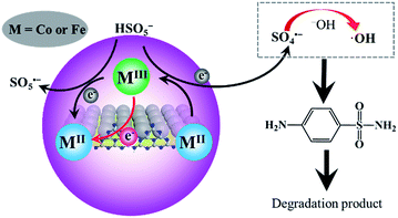 |
| | Fig. 8 Mechanisms of PMS activation by CoFe2O4–CNS for oxidative degradation of SA. | |
The above results indicate that CoFe2O4–CNS could be used as an attractive heterogenous catalyst for sustainable pollutant control application, but issues such as CoII leaching and robustness in real environment are still to be addressed in future studies. In addition, the photocatalytic activity of g-C3N4 may also be taken advantage of to further strengthen the performance of such SO4˙−-based treatment processes.55,56
4. Conclusions
A novel CoFe2O4–CNS nanocomposite was fabricated for PMS activation and SA degradation. It showed obvious advantage over conventional CoFe2O4 catalyst in terms of catalytic activity, stability, and magnetic separation performance. The superior performance of the CoFe2O4–CNS was mainly ascribed to a good synergy between the CoFe2O4 and CNS: the CNS with large specific surface area significantly improved the dispersion of CoFe2O4 particles, not only enabling the exposure of more active sites to favor PMS activation but also allowing more efficient magnetic separation and resuspension of the material; the CNS also directly contributed to the regeneration of ![[triple bond, length as m-dash]](https://www.rsc.org/images/entities/char_e002.gif) CoII and
CoII and ![[triple bond, length as m-dash]](https://www.rsc.org/images/entities/char_e002.gif) FeII, thereby further improving the catalyst stability during repeated use. This material has the potential for more sustainable water treatment and environmental remediation applications.
FeII, thereby further improving the catalyst stability during repeated use. This material has the potential for more sustainable water treatment and environmental remediation applications.
Conflicts of interest
There are no conflicts to declare.
Acknowledgements
The authors wish to thank the National Natural Science Foundation of China (51522812, 51538012, 51778597) for the financial support of this work, and thank Dr Zheng Chen at Xi'an Jiaotong-Liverpool University for providing support for the TOC analysis.
References
- J. Zou, J. Ma, L. Chen, X. Li, Y. Guan, P. Xie and C. Pan, Environ. Sci. Technol., 2013, 47, 11685–11691 CrossRef CAS PubMed.
- W. D. Oh, Z. Dong, Z. T. Hu and T. T. Lim, J. Mater. Chem. A, 2015, 3, 22208–22217 CAS.
- F. Ghanbari and M. Moradi, Chem. Eng. J., 2017, 310, 41–62 CrossRef CAS.
- H. Chen and K. C. Carroll, Environ. Pollut., 2016, 215, 96–102 CrossRef CAS PubMed.
- J. Wang, Z. Yao, Y. Wang, Q. Xia, H. Chu and Z. Jiang, Environ. Pollut., 2017, 224, 552–558 CrossRef CAS PubMed.
- G. P. Anipsitakis and D. D. Dionysiou, Environ. Sci. Technol., 2004, 38, 3705–3712 CrossRef CAS PubMed.
- Y. Fan, W. Ma, J. He and Y. Du, RSC Adv., 2017, 7, 36193–36200 RSC.
- W. Chu, W. K. Choy and C. Y. Kwan, J. Agric. Food Chem., 2007, 55, 5708–5713 CrossRef CAS PubMed.
- Q. Yang, H. Choi and D. D. Dionysiou, Appl. Catal., B, 2007, 74, 170–178 CrossRef CAS.
- W. Zhang, H. L. Tay, S. S. Lim, Y. Wang, Z. Zhong and R. Xu, Appl. Catal., B, 2010, 95, 93–99 CrossRef CAS.
- Y. Ren, L. Lin, J. Ma, J. Yang, J. Feng and Z. Fan, Appl. Catal., B, 2015, 165, 572–578 CrossRef CAS.
- L. M. Rossi, N. J. S. Costa, F. P. Silva and R. Wojcieszak, Green Chem., 2014, 16, 2906–2933 RSC.
- Y. C. Kim, S. Han and S. Hong, Water Sci. Technol., 2011, 64, 469–476 CrossRef CAS PubMed.
- Y. Yao, Y. Cai, F. Lu, F. Wei, X. Wang and S. Wang, J. Hazard. Mater., 2014, 270, 61–70 CrossRef CAS PubMed.
- X. Qi, Q. Hu, J. Xu, R. Xie, Y. Jiang, W. Zhong and Y. Du, RSC Adv., 2016, 6, 11382–11387 RSC.
- B. Buchholcz, H. Haspel, A. Oszko, A. Kukovecz and Z. Konya, RSC Adv., 2017, 7, 16410–16422 RSC.
- M. Wei, L. Gao, J. Li, J. Fang, W. Cai, X. Li and A. Xu, J. Hazard. Mater., 2016, 316, 60–68 CrossRef CAS PubMed.
- P. Niu, L. Zhang, G. Liu and H.-M. Cheng, Adv. Funct. Mater., 2012, 22, 4763–4770 CrossRef CAS.
- J. Xu, Y. Wang and Y. Zhu, Langmuir, 2013, 29, 10566–10572 CrossRef CAS PubMed.
- J. Xiao, J. Rabeah, J. Yang, Y. Xie, H. Cao and A. Brückner, ACS Catal., 2017, 7, 6198–6206 CrossRef CAS.
- H. Zhao, H. Yu, X. Quan, S. Chen, Y. Zhang, H. Zhao and H. Wang, Appl. Catal., B, 2014, 152–153, 46–50 CrossRef CAS.
- S. Huang, Y. Xu, M. Xie, H. Xu, M. He, J. Xia, L. Huang and H. Li, Colloids Surf., A, 2015, 478, 71–80 CrossRef CAS.
- Y. Yao, G. Wu, F. Lu, S. Wang, Y. Hu, J. Zhang, W. Huang and F. Wei, Environ. Sci. Pollut. Res., 2016, 23, 21833–21845 CrossRef CAS PubMed.
- K. L. Corp and C. W. Schlenker, J. Am. Chem. Soc., 2017, 139, 7904–7912 CrossRef CAS PubMed.
- X. Zhang, X. Xie, H. Wang, J. Zhang, B. Pan and Y. Xie, J. Am. Chem. Soc., 2013, 135, 18–21 CrossRef CAS PubMed.
- S. G. Dmitrienko, E. V. Kochuk, V. V. Apyari, V. V. Tolmacheva and Y. A. Zolotov, Anal. Chim. Acta, 2014, 850, 6–25 CrossRef CAS PubMed.
- S. Dong, Y. Pi, Q. Li, L. Hu, Y. Li, X. Han, J. Wang and J. Sun, J. Alloys Compd., 2016, 663, 1–9 CrossRef CAS.
- W. Zhu, J. Liu, S. Yu, Y. Zhou and X. Yan, J. Hazard. Mater., 2016, 318, 407–416 CrossRef CAS PubMed.
- A. A. Ahmed, S. Thiele-Bruhn, P. Leinweber and O. Kühn, Sci. Total Environ., 2016, 559, 347–355 CrossRef CAS PubMed.
- S. T. Khankhasaeva, D. V. Dambueva, E. T. Dashinamzhilova, A. Gil, M. A. Vicente and M. N. Timofeeva, J. Hazard. Mater., 2015, 293, 21–29 CrossRef CAS PubMed.
- J. Giménez, B. Bayarri, Ó. González, S. Malato, J. Peral and S. Esplugas, ACS Sustainable Chem. Eng., 2015, 3, 3188–3196 CrossRef.
- E. Saputra, S. Muhammad, H. Sun, H. M. Ang, M. O. Tade and S. Wang, Environ. Sci. Technol., 2013, 47, 5882–5887 CrossRef CAS PubMed.
- A. Yan, X. Liu, R. Shi, N. Zhang, R. Yi, Y. Li, G. Gao and G. Qiu, Solid State Commun., 2008, 146, 483–486 CrossRef CAS.
- A. Yan, X. Liu, R. Yi, R. Shi, N. Zhang and G. Qiu, J. Phys. Chem. C, 2008, 112, 8558–8563 CAS.
- L. J. Xu, W. Chu and L. Gan, Chem. Eng. J., 2015, 263, 435–443 CrossRef CAS.
- T. Li, Y. Lv, J. Su, Y. Wang, Q. Yang, Y. Zhang, J. Zhou, L. Xu, D. Sun and Y. Tang, Adv. Sci., 2017, 4, 1700226 CrossRef.
- C. D. Pham, J. Chang, M. A. Zurbuchen and J. P. Chang, ACS Appl. Mater. Interfaces, 2017, 9, 36980–36988 CAS.
- N. Dong, F. He, J. Xin, Q. Wang, Z. Lei and B. Su, Mater. Res. Bull., 2016, 80, 186–190 CrossRef CAS.
- N. Dong, M. Zhong, P. Fei, Z. Lei and B. Su, J. Alloys Compd., 2016, 660, 382–386 CrossRef CAS.
- G. P. Anipsitakis and D. D. Dionysiou, Environ. Sci. Technol., 2003, 37, 4790–4797 CrossRef CAS PubMed.
- T. Zhang, H. Zhu and J. P. Croué, Environ. Sci. Technol., 2013, 47, 2784–2791 CrossRef CAS PubMed.
- H. Liang, H. Sun, A. Patel, P. Shukla, Z. H. Zhu and S. Wang, Appl. Catal., B, 2012, 127, 330–335 CrossRef CAS.
- Y. Lei, C.-S. Chen, J. Ai, H. Lin, Y.-H. Huang and H. Zhang, RSC Adv., 2016, 6, 866–871 RSC.
- Y. Feng, J. Liu, D. Wu, Z. Zhou, Y. Deng, T. Zhang and K. Shih, Chem. Eng. J., 2015, 280, 514–524 CrossRef CAS.
- G. Friedman and B. Yellen, Curr. Opin. Colloid Interface Sci., 2005, 10, 158–166 CrossRef CAS.
- Y. Cai and X. M. Hu, Desalination, 2016, 391, 16–29 CrossRef CAS.
- X. Li, Z. Wang, B. Zhang, A. I. Rykov, M. A. Ahmed and J. Wang, Appl. Catal., B, 2016, 181, 788–799 CrossRef CAS.
- Y. Zhao, X. Ma, P. Xu, H. Wang, Y. Liu and A. He, J. Hazard. Mater., 2018, 341, 228–237 CrossRef PubMed.
- X. J. Yang, X. M. Xu, J. Xu and Y. F. Han, J. Am. Chem. Soc., 2013, 135, 16058–16061 CrossRef CAS PubMed.
- W. Ho, Z. Zhang, W. Lin, S. Huang, X. Zhang, X. Wang and Y. Huang, ACS Appl. Mater. Interfaces, 2015, 7, 5497–5505 CAS.
- X. Duan, Z. Ao, H. Sun, S. Indrawirawan, Y. Wang, J. Kang, F. Liang, Z. H. Zhu and S. Wang, ACS Appl. Mater. Interfaces, 2015, 7, 4169–4178 CAS.
- X. Duan, Z. Ao, H. Sun, L. Zhou, G. Wang and S. Wang, Chem. Commun., 2015, 51, 15249–15252 RSC.
- X. Duan, H. Sun, Y. Wang, J. Kang and S. Wang, ACS Catal., 2015, 5, 553–559 CrossRef CAS.
- X. Duan, K. O'Donnell, H. Sun, Y. Wang and S. Wang, Small, 2015, 11, 3036–3044 CrossRef CAS PubMed.
- C. Y. Wang, X. Zhang, H. B. Qiu, G. X. Huang and H. Q. Yu, Appl. Catal., B, 2017, 205, 615–623 CrossRef CAS.
- W. J. Ong, L. L. Tan, Y. H. Ng, S. T. Yong and S. P. Chai, Chem. Rev., 2016, 116, 7159–7329 CrossRef CAS PubMed.
Footnote |
| † Electronic supplementary information (ESI) available. See DOI: 10.1039/c7ra09665h |
|
| This journal is © The Royal Society of Chemistry 2017 |
Click here to see how this site uses Cookies. View our privacy policy here.  Open Access Article
 *ab
*ab
![[thin space (1/6-em)]](https://www.rsc.org/images/entities/char_2009.gif) :
:![[thin space (1/6-em)]](https://www.rsc.org/images/entities/char_2009.gif) 80, v/v) at a flow rate of 0.5 mL min−1 was used as the mobile phase. The column temperature was 30 °C. The detection wavelength was set at 268 nm.
80, v/v) at a flow rate of 0.5 mL min−1 was used as the mobile phase. The column temperature was 30 °C. The detection wavelength was set at 268 nm.


![[double bond, length as m-dash]](https://www.rsc.org/images/entities/char_e001.gif) C groups, denoted as N1), 399.9 eV (amino groups ((C)2–N–H) connecting with structural defects and incomplete condensation, denoted as N2), 401.2 eV (N–(C)3 in the aromatic ring, denoted as N3). For the CoFe2O4–CNS, the intensity of N1 peak decreased by 2% after the reaction while that of N2 peak increased by 2%. The g-C3N4 contains abundant graphitic N corresponding to the sp2-bonded N that are involved in the triazine rings (N1)50 and can induce electron transfer from adjacent carbon atoms to nitrogen. Such a feature renders the sp2 carbon layer of the g-C3N4 a high chemical activity.51–54 Therefore, it is possible that the delocalized electrons from grapheme N on the zigzag edges of CNS might also contributed to the reduction of MIII (M = Co or Fe) species, thus the C–N
C groups, denoted as N1), 399.9 eV (amino groups ((C)2–N–H) connecting with structural defects and incomplete condensation, denoted as N2), 401.2 eV (N–(C)3 in the aromatic ring, denoted as N3). For the CoFe2O4–CNS, the intensity of N1 peak decreased by 2% after the reaction while that of N2 peak increased by 2%. The g-C3N4 contains abundant graphitic N corresponding to the sp2-bonded N that are involved in the triazine rings (N1)50 and can induce electron transfer from adjacent carbon atoms to nitrogen. Such a feature renders the sp2 carbon layer of the g-C3N4 a high chemical activity.51–54 Therefore, it is possible that the delocalized electrons from grapheme N on the zigzag edges of CNS might also contributed to the reduction of MIII (M = Co or Fe) species, thus the C–N![[double bond, length as m-dash]](https://www.rsc.org/images/entities/char_e001.gif) C groups would be disrupted to form –NH2 or –NH groups (eqn (6) and (7)) (Fig. S7(c)†). This was verified by the FT-IR spectra of CoFe2O4–CNS which showed increased –NH2 or –NH groups (absorption centred at 3184 cm−1)17 and decreased C–N
C groups would be disrupted to form –NH2 or –NH groups (eqn (6) and (7)) (Fig. S7(c)†). This was verified by the FT-IR spectra of CoFe2O4–CNS which showed increased –NH2 or –NH groups (absorption centred at 3184 cm−1)17 and decreased C–N![[double bond, length as m-dash]](https://www.rsc.org/images/entities/char_e001.gif) C groups after the reaction (Fig. S7(b)†).
C groups after the reaction (Fig. S7(b)†).![[triple bond, length as m-dash]](https://www.rsc.org/images/entities/char_e002.gif) CoII + HSO5− →
CoII + HSO5− → ![[triple bond, length as m-dash]](https://www.rsc.org/images/entities/char_e002.gif) CoIII + SO4˙− + OH−
CoIII + SO4˙− + OH−
![[triple bond, length as m-dash]](https://www.rsc.org/images/entities/char_e002.gif) CoIII + HSO5− →
CoIII + HSO5− → ![[triple bond, length as m-dash]](https://www.rsc.org/images/entities/char_e002.gif) CoII + SO5˙− + H+
CoII + SO5˙− + H+
![[triple bond, length as m-dash]](https://www.rsc.org/images/entities/char_e002.gif) FeII + HSO5− →
FeII + HSO5− → ![[triple bond, length as m-dash]](https://www.rsc.org/images/entities/char_e002.gif) FeIII + SO4˙− + OH−
FeIII + SO4˙− + OH−
![[triple bond, length as m-dash]](https://www.rsc.org/images/entities/char_e002.gif) FeIII + HSO5− →
FeIII + HSO5− → ![[triple bond, length as m-dash]](https://www.rsc.org/images/entities/char_e002.gif) FeIII + SO5˙− + H+
FeIII + SO5˙− + H+
![[triple bond, length as m-dash]](https://www.rsc.org/images/entities/char_e002.gif) CoIII + e(C–N
CoIII + e(C–N![[double bond, length as m-dash]](https://www.rsc.org/images/entities/char_e001.gif) C)− →
C)− → ![[triple bond, length as m-dash]](https://www.rsc.org/images/entities/char_e002.gif) CoII + –NH2/–NH
CoII + –NH2/–NH
![[triple bond, length as m-dash]](https://www.rsc.org/images/entities/char_e002.gif) FeIII + e(C–N
FeIII + e(C–N![[double bond, length as m-dash]](https://www.rsc.org/images/entities/char_e001.gif) C)− →
C)− → ![[triple bond, length as m-dash]](https://www.rsc.org/images/entities/char_e002.gif) FeII + –NH2/–NH
FeII + –NH2/–NH
![[triple bond, length as m-dash]](https://www.rsc.org/images/entities/char_e002.gif) CoII and
CoII and ![[triple bond, length as m-dash]](https://www.rsc.org/images/entities/char_e002.gif) FeII) play a centre role in converting PMS into SO4˙−, with themselves being oxidized into
FeII) play a centre role in converting PMS into SO4˙−, with themselves being oxidized into ![[triple bond, length as m-dash]](https://www.rsc.org/images/entities/char_e002.gif) CoIII and
CoIII and ![[triple bond, length as m-dash]](https://www.rsc.org/images/entities/char_e002.gif) FeIII. The latter can be reduced back to bi-valent metals by PMS, generating less active SO5˙−. However, this step is relatively slow, leading to decreased content of
FeIII. The latter can be reduced back to bi-valent metals by PMS, generating less active SO5˙−. However, this step is relatively slow, leading to decreased content of ![[triple bond, length as m-dash]](https://www.rsc.org/images/entities/char_e002.gif) CoII and
CoII and ![[triple bond, length as m-dash]](https://www.rsc.org/images/entities/char_e002.gif) FeII during the catalytic reaction. Here, the introduction of CNS allowed an improved dispersion of the CoFe2O4 particles, thus more active sites of
FeII during the catalytic reaction. Here, the introduction of CNS allowed an improved dispersion of the CoFe2O4 particles, thus more active sites of ![[triple bond, length as m-dash]](https://www.rsc.org/images/entities/char_e002.gif) CoII and
CoII and ![[triple bond, length as m-dash]](https://www.rsc.org/images/entities/char_e002.gif) FeII could be exposed. In addition, the regeneration of
FeII could be exposed. In addition, the regeneration of ![[triple bond, length as m-dash]](https://www.rsc.org/images/entities/char_e002.gif) CoII and
CoII and ![[triple bond, length as m-dash]](https://www.rsc.org/images/entities/char_e002.gif) FeII was reinforced by graphitic N on the zigzag edges of CNS. Such a synergy between CoFe2O4 and CNS significantly raised the catalytic activity and stability for PMS activation.
FeII was reinforced by graphitic N on the zigzag edges of CNS. Such a synergy between CoFe2O4 and CNS significantly raised the catalytic activity and stability for PMS activation.![[triple bond, length as m-dash]](https://www.rsc.org/images/entities/char_e002.gif) CoII and
CoII and ![[triple bond, length as m-dash]](https://www.rsc.org/images/entities/char_e002.gif) FeII, thereby further improving the catalyst stability during repeated use. This material has the potential for more sustainable water treatment and environmental remediation applications.
FeII, thereby further improving the catalyst stability during repeated use. This material has the potential for more sustainable water treatment and environmental remediation applications.


