 Open Access Article
Highly efficient electrocatalysts with CoO/CoFe2O4 composites embedded within N-doped porous carbon materials prepared by hard-template method for oxygen reduction reaction†
Xinxin Jina,
Yu Jiangab,
Qi Hua,
Shaohua Zhanga,
Qike Jianga,
Li Chenc,
Ling Xub,
Yan Xie *a and
Jiahui Huang
 *a
*a
aGold Catalysis Research Center, State Key Laboratory of Catalysis, Dalian Institute of Chemical Physics, Chinese Academy of Sciences, 457 Zhongshan Road, Dalian 116023, P. R. China. E-mail: jiahuihuang@dicp.ac.cn; yanxie@dicp.ac.cn
bCollege of Chemistry and Chemical Engineering, Inner Mongolia University for Nationalities, 996 Xilamulun Street, Tongliao 028000, P. R. China
cShanghai Key Laboratory of Green Chemistry and Chemical Processes, School of Chemistry and Molecular Engineering, East China Normal University, North Zhongshan Road 3663, Shanghai 200062, P. R. China
First published on 15th December 2017
Abstract
Low-cost dual transition metal (Fe and Co) based non-noble metal electrocatalysts (NNMEs) have been explored to enhance the oxygen reduction reaction (ORR) performance in both alkaline and acidic solution. In this work, novel NNMEs derived from iron, cobalt and N-doped porous carbon materials (FeCo/NPC) were fabricated with magnesium oxide (MgO) as the hard-template. By optimizing the pyrolysis temperature (600 to 1000 °C) and the molar ratio of Fe to Co (Co, FeCo3, FeCo, Fe3Co, Fe), the highly active electrocatalyst FeCo/NPC (900) for ORR in alkaline solution was prepared, which possessed a large surface area of 958 m2 g−1. The onset potential (Eonset) and half-wave potential (E1/2) of FeCo/NPC (900) were 0.934 V and 0.865 V, respectively, comparable to the best values of NNMEs reported so far in ORR tests under alkaline conditions. Additionally, FeCo/NPC (900) exhibited better electrocatalytic properties than commercial Pt/C in terms of durability and the tolerance to methanol in alkaline media.
Introduction
Traditionally, the oxygen reduction reaction (ORR) is predominantly conducted with Pt-based electrocatalysts to achieve optimal activity in the applications of proton exchange membrane fuel cells (PEMFCs).1,2 The prohibitive cost, scarcity and vulnerability of platinum significantly impede the commercialization of PEMFCs. Thus, it is crucial to develop alternatives to replace Pt and its alloys by employing non-noble metal electrocatalysts (NNMEs).3,4 As reported, the pursuit of NNMEs can be divided into several types, such as N4-metallomacrocyclic (MeN4) complexes,5–7 metal oxides,8,9 metal carbides or nitrides,10,11 heteroatom-doped carbon materials12–16 and others.17–21Generally, one of the most promising approach to synthesize highly efficient NNMEs for ORR is to prepare transition metal-based and nitrogen-doped carbon materials, shortly noted as Me/N/C (Me = transition metal, especially Fe or/and Co). The pioneering work of MeN4 was investigated for ORR by Jasinski in 1964.7 Later, in 1989 Gupta and co-workers reported that transition metal (Co or Fe) mixed with polyacrylonitrile (PAN) loaded on carbon materials exhibited very promising performance in ORR.22 Here, the nitrile groups in PAN could be converted to pyridyl groups during pyrolysis process to provide binding sites for transition metals. Since then, a number of efficient NNMEs were prepared from economical transition metals and N-containing precursors by various methods. Among these N-containing precursors, pyrrole, aniline, and phenanthroline (phen) were soon found to be the most promising nitrogen source. For instance, in 2009, Lefèvre and co-workers reported that microporous carbon supported iron-based electrocatalysts showed the highest volumetric activity of 99 A cm−3, almost equal to that of Pt-based cathode (Pt loading of 0.4 mg cm−2) at a cell voltage of ≥ 0.9 V.23 Later, another breakthrough was achieved by Zelenay and co-workers in 2011. They reported that Fe/N/C electrocatalysts, which were derived from the commercial carbon (Kejenblack EC-300J), polyaniline (PANI) and transition metal precursors [Co(II) or/and Fe(III)] through pyrolysis, acid leaching and a second pyrolysis, showed a remarkable performance with an excellent four electron selectivity (H2O2 yield <1%) in acidic solution because of the synergistic effect between transition metals and nitrogen-containing active sites.19
Usually, the large specific surface area and porous structure of NNMEs are crucial for mass transport and exposure of active sites to boost the ORR performance. The hard templates like silica (SBA-15) and silica nanoparticles (NPs) have been used to fabricate highly efficient porous NNMEs with high surface area. For example, Fe–N-doped ordered mesoporous carbon catalysts (FeX@NOMC, where X represents the mass percentage of Fe, X = 5, 10, 25) were prepared by using SBA-15 as a hard template. After pyrolysis, FeX@NOMC was obtained by etching carbon@silica composite with 10 wt% hydrofluoric acid (HF) aqueous solution.24 Another report is about mesoporous Co–N–C electrocatalysts, which were prepared by using vitamin B12 (VB12) as carbon source, and silica NPs, ordered mesoporous silica SBA-15 or montmorillonite (MMT) as templates.25 The resulting mesoporous structures (VB12/silica NPs, VB12/SBA-15 or VB12/MMT) were pyrolyzed under N2 flow at high temperature and etched by HF aqueous solution. Among these three electrocatalysts, VB12/silica NPs electrocatalyst exhibited the best performance in ORR due to its highest surface area and well-defined porous structures. Nevertheless, the electrochemical properties of these NNMEs are not yet high enough for practical application and thus should be further improved by optimizing synthesis parameters.
In this work, we demonstrated a novel porous NNME (FeCo/NPC) with dual-transition metal (Fe and Co) based N-doped porous carbon (NPC) materials by virtue of a hard template method. Here, magnesium oxide (MgO), which can be easily removed by hydrochloric acid (HCl) aqueous solution, was employed as template to fabricate porous architecture of NNMEs. Phen with high nitrogen content and adipic acid with dual carboxyl groups were used as N-containing ligands and carbon sources. In studying the effects of N-doped carbon materials and transition metals on ORR, we found that FeCo/NPC (900) with a large surface area of 958 m2 g−1 and micro/meso/macro hierarchical porous structure exhibited an outstanding ORR activity in 0.1 M KOH electrolyte. Even compared with 20 wt% Pt/C, FeCo/NPC (900) electrocatalyst displayed better durability and methanol tolerance.
Experimental
Chemicals and materials
Magnesium oxide (MgO) nanoparticle was purchased from Aladdin Industrial Co. Ltd. (Shanghai, China). Ethanol and adipic acid were purchased from Sinopharm Chemical Reagent Co. Ltd. (GR, Shanghai, China) and Acros Organic (Geel, Belgium), respectively. Phenanthroline (phen) and hydrochloric acid were purchased from Tianjin Kemiou Chemical Reagent Co. Ltd. Iron(III) chloride hexahydrate (97.0–102.0%) and Cobalt(II) nitrate hexahydrate (99%) were purchased from Alfa Aesar (China) Chemicals Co., Ltd and Acros Organic (Geel, Belgium), respectively. All other chemicals were used as received from the suppliers without further purification.Morphology and structure characterization
The electrocatalysts were observed by the transmission electron microscopic (TEM), TEM/energy dispersive X-ray (EDX), high resolution TEM (HRTEM) and element mapping measurements on a JEM-2100 operating at 200 kV and FEI TECNAI G2 F30 at 300 kV, respectively. Brunauer Emmet Teller (BET) surface area was determined by using a MIC ASAP 2020 instrument with nitrogen adsorption using the Barrett Joyner Halenda (BJH) method. The pore size distribution of micropores (<2 nm) and mesopores (2–50 nm) were analyzed by the Horváth–Kawazoe (HK) and the BJH method, respectively. X-ray photoelectron spectroscopy (XPS) was carried out on a Thermo ESCALAB 250Xi photoelectron spectrometer. X-ray powder diffraction (XRD) was recorded on a PANalytical Empyrean-100 diffractometer with Cu Kα radiation at a scanning rate at 2° min−1. The concentration of Fe and Co was measured by inductively coupled plasma optical emission spectroscopy (ICP-OES) (ICPS-8100, SHIMADZU). The sample was pretreated at 800 °C for 30 min under air in furnace, and then dissolved in 300 μL aqua regia for 12 h and finally used deionized water titration to 25 mL.Preparation of FeCo/NPC (900)
The porous NNME of FeCo/NPC (900) was fabricated by a hard-template synthesis. Briefly, 300 mg phen, 221 mg adipic acid and the mixture of 614 mg FeCl3·6H2O and 661 mg Co(NO3)2·6H2O were dissolved in 100 mL ethanol, then 700 mg MgO was added into the solution. After stirring for 30 min, the mixture was dried by using a rotary evaporator. The obtained composites were then pyrolyzed under the flowing Ar atmosphere at 900 °C for 2 h. The MgO NPs were etched out by 2.0 M HCl aqueous solution. The obtained carbonized samples were further washed by water until the filtrate was neutral. Finally, the materials were dried at 60 °C in a drying oven for 12 h. In addition, FeCo/NPC was also pyrolyzed at relative lower temperature of 600 °C, 700 °C, 800 °C and even higher temperature of 1000 °C, respectively. For comparison, NNME electrocatalysts without metal salts and containing only Co, only Fe or containing both Co and Fe with different molar ratios were also synthesized according to the process above.Electrochemical characterization
The as-prepared samples were measured in a standard three-electrode electrochemical cells by CHI 760E (CH Instruments, Shanghai, China) with a Hg/HgO as a reference electrode, a Pt net as a counter electrode and the catalyst-coated glassy carbon (GC) disk as a working electrode. The electrolyte (0.1 M KOH) was provided by ultrapure water (18.2 MΩ cm). Here, the catalyst ink was prepared to be 2 mg mL−1 by mixing the catalyst with ethanol, ultrapure water and 5 wt% Nafion (Vethanol![[thin space (1/6-em)]](https://www.rsc.org/images/entities/char_2009.gif) :
:![[thin space (1/6-em)]](https://www.rsc.org/images/entities/char_2009.gif) Vwater
Vwater![[thin space (1/6-em)]](https://www.rsc.org/images/entities/char_2009.gif) :
:![[thin space (1/6-em)]](https://www.rsc.org/images/entities/char_2009.gif) VNafiion = 9
VNafiion = 9![[thin space (1/6-em)]](https://www.rsc.org/images/entities/char_2009.gif) :
:![[thin space (1/6-em)]](https://www.rsc.org/images/entities/char_2009.gif) 1
1![[thin space (1/6-em)]](https://www.rsc.org/images/entities/char_2009.gif) :
:![[thin space (1/6-em)]](https://www.rsc.org/images/entities/char_2009.gif) 0.06), followed by ultrasonication for at least 10 min. Then 60 μL ink was dropped onto the GC disk. The geometric surface area of GC was 0.19625 cm2. The total mass loading of NNMEs was 0.6 mg cm−2. For comparison, the Johnson Matthey (JM) 20 wt% Pt/C ink was prepared to be 1 mg mL−1, and 20 μL was drawn and loaded onto the GC. As a result, the platinum loading was 20 μgPt cm−2.
0.06), followed by ultrasonication for at least 10 min. Then 60 μL ink was dropped onto the GC disk. The geometric surface area of GC was 0.19625 cm2. The total mass loading of NNMEs was 0.6 mg cm−2. For comparison, the Johnson Matthey (JM) 20 wt% Pt/C ink was prepared to be 1 mg mL−1, and 20 μL was drawn and loaded onto the GC. As a result, the platinum loading was 20 μgPt cm−2.
Initially, cyclic voltammetry (CV) curves were used to clean the surface of electrocatalysts in N2-saturated KOH solution. The cycling potential range was from 0.087 to 1.087 V (vs. RHE) and the scanning rate was 100 mV s−1. Then, a constant flow rate of oxygen was bubbled into 0.1 M KOH solution at least 10 min to get a O2-saturated atmosphere. ORR polarization curves of electrocatalysts with different rotation rates from 400 to 2025 rpm were evaluated in O2-saturated alkaline solution at a scanning rate of 5 mV s−1 with the potential range from 0.087 to 1.087 V (vs. RHE). Thirdly, the slopes of their best linear fit lines were used to calculate the number of electrons transferred (n) on the basis of the K–L equation as follows:
 | (1) |
| B = 0.62nFAC0D02/3ν−1/6 | (2) |
![[thin space (1/6-em)]](https://www.rsc.org/images/entities/char_2009.gif) 485C mol−1), D0 is the diffusion coefficient of O2 (D = 1.93 × 10⁻⁵ cm2 s−1), ν is the kinetic viscosity of the solution (ν = 0.01 cm2 s−1), C0 is the concentration of O2 dissolved in electrolyte (C = 1.2 × 10⁻⁶ mol cm−3), and ω is the electrode rotation speed.
485C mol−1), D0 is the diffusion coefficient of O2 (D = 1.93 × 10⁻⁵ cm2 s−1), ν is the kinetic viscosity of the solution (ν = 0.01 cm2 s−1), C0 is the concentration of O2 dissolved in electrolyte (C = 1.2 × 10⁻⁶ mol cm−3), and ω is the electrode rotation speed.
The rotating ring disk electrode (RRDE) purchased from PINE instrument in USA was used to obtain ORR polarization curves in O2-saturated 0.1 M KOH media from 0.087 to 1.087 V (vs. RHE). The rotation rate was 1600 rpm and the positive scanning rate was 5 mV s−1. The ORR polarization curves were kept under a certain potential of 1.087 V (vs. RHE). Herein, the % HO2− and n were calculated by the followed equations:
 | (3) |
 | (4) |
As for the accelerated durability test (ADT), the freshly prepared electrode was repeatedly scanned for 2000 cycles from 0.487 to 1.087 V (vs. RHE) at the scanning rate of 100 mV s−1. The ORR polarization curves of FeCo/NPC (900) and commercial electrocatalyst of Pt/C were obtained after certain cycle number (0, 200, 400, 600, 1000, 1500 and 2000 cycles) to track the degradation trend.
The current–time (i–t) curves of FeCo/NPC (900) and 20 wt% Pt/C were measured at the constant potential of 0.587 V (vs. RHE) for 1000 s at a rotation rate of 1600 rpm in O2-saturated 0.1 M KOH solution. And the 10% (v/v) methanol was injected at approximately 450 s to confirm the selectivity of the electrocatalysts between ORR and methanol oxidation.
Results and discussion
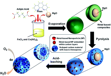
The synthesis of FeCo/NPC electrocatalyst was illustrated in Scheme 1. Dual transition metal precursors, FeCl3·6H2O and Co(NO3)2·6H2O, were dissolved in the ethanol solution in presence of phen and adipic acid, and then commercial MgO NPs were added into the above solution. After vigorously stirring for 30 min, the as-prepared solution was evaporated at room temperature. The collected powder was pyrolyzed at different temperatures under Ar flow and then etched by HCl aqueous solution (see the details of fabrication process in the Experimental section). For simplification, the final product was labelled as FeCo/NPC (T), where T corresponded to the pyrolysis temperature.Firstly, the structure and morphology of as-prepared NNME, such as FeCo/NPC (900) was investigated by X-ray diffraction (XRD), scanning electron microscopy (SEM), transmission electron microscopy (TEM), high-angle annular dark-field scanning transmission electron microscopy (HAADF-STEM) and element mapping. As shown in Fig. 1a, the XRD pattern of FeCo/NPC (900) confirmed the formation of CoFe2O4 (JCPDS card no. 22-1086) in the hybrids.26 The formation of CoFe2O4 NPs should be caused by the reaction of transition metal species with the tiny amount of oxygen, which may be absorbed in the solution during the synthesis process or contained in the impure Ar used for the pyrolysis step. Several defined diffraction peaks at 2θ values of 30.1°, 35.4°, 37.1°, 43.1°, 54.5°, 56.9°, 62.6°, and 74.0° could be indexed to the (220), (311), (222), (400), (422), (511), (440) and (533) plane of CoFe2O4. The intense peaks around 26.4°, 44.4° and 54.5° could be indexed to (002), (101) and (004) plane of carbon, respectively. The results above indicated that CoFe2O4 NPs should be embedded within carbon materials, otherwise CoFe2O4 would be removed during etching by HCl aqueous solution. For comparison, different ratio of Fe and Co in the NNMEs were tested by XRD in Fig. S1,† it is found that the peaks of graphite carbon became more sharper with the increasing ratio of Fe, while the increasing ratio of Co showed the opposite phenomenon. It indicated the indicative of crystallite size or lack of long-range order of NNMEs could be effected by iron during the process of carbonization. As shown in Fig. 1b, the SEM images of FeCo/NPC (900) demonstrated that abundant mesoporous and macroporous graphitic shells were formed after the removal of MgO (TEM image of commercial MgO was showed in Fig. 1c). Here, hard-template MgO displayed a crucial role in the creation of meso/macroporous graphitic shells,27 which were very helpful to improve the conductivity of electrocatalysts and enhance the mass transport through the open porous network.28 The magnified SEM image in Fig. 1d showed that the wall of macropores contained large amount of mesopores. These mesopores might originate from the removal of transition metal based NPs during acid-leaching after pyrolysis (Fig. 1d and e)29 TEM characterization in Fig. 1e further demonstrated that some NPs were embedded in the porous carbon materials. The high-resolution TEM (HRTEM) in Fig. 1f confirmed that the lattice distance of these NPs was around 0.20 nm, which was very close with the lattice space of the plane (400) or (200) of CoFe2O4 and CoO, respectively. Moreover, typical CoO/CoFe2O4 NPs were entirely encapsulated by carbon layers (Fig. 1g). According to the TEM/energy dispersive X-ray (EDX) in Fig. S2,† the more content of Co indicating that not only the existence of CoFe2O4 but also other cobalt species like CoO that consistent well with the discussion above. Besides, micropores were observed in the carbon materials in Fig. 1h.
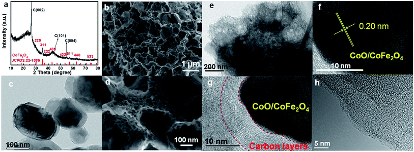 | ||
| Fig. 1 . XRD pattern (a), SEM images (b, d), TEM image (e–g) and HRTEM image (h) of FeCo/NPC (900) and the TEM image of MgO (c). | ||
The HAADF-STEM images and element mapping analyses of FeCo/NPC (900) in Fig. 2a indicated that after pyrolysis and acid washing some NPs were removed, causing the formation of some mesoporous defects, but some NPs still existed due to the protection of carbon layers. The presence of C, O, N, Fe and Co components in the hybrids (Fig. 2c–g) were observed by element mapping analyses of the selected area in Fig. 2b. The element of O and N were uniformly dispersed on carbon materials. However, Fe and Co co-existed as isolated NPs. These NPs should be attributed to CoFe2O4 NPs according to XRD and TEM characterizations in Fig. 1.
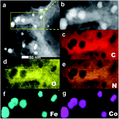 | ||
| Fig. 2 HAADF-STEM image of FeCo/NPC (900) (a), the selected area (b), the corresponding element mapping images of C (c), O (d), N (e), Fe (f) and Co (g). | ||
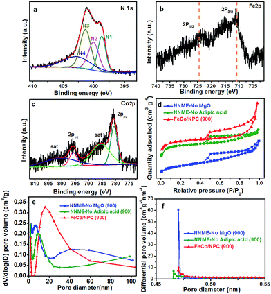
The X-ray photoelectron spectroscopy (XPS) analysis was further performed to examine the chemical states of FeCo/NPC (900). As shown in Fig. 3a, the high-resolution spectrum of N 1s could be divided into four types, including N1 (pyridinic N, 398.7 eV, 21%), N2 (pyrrolic N, 400.0 eV, 23%), N3 (graphitic N, 401.4 eV, 32%) and N4 (oxidized N, 402.8 eV, 24%). The total N content of FeCo/NPC (900) was calculated to be ∼3.9% with relative to carbon. The high-resolution XPS spectra of Fe 2p and Co 2p, indicated the presence of Fe and Co in FeCo/NPC (900). The Fe 2p in Fig. 3b exhibited two major peaks at the binding energy of 710.9 eV and 724.5 eV, which corresponded to Fe 2p3/2 and 2p1/2, respectively. The high resolution diagram in Fig. 3c displayed two peaks at 780.6 eV and 795.8 eV (with a spin–orbit separation of 15.2 eV), which could be assigned to the electronic state of Co 2p3/2 and 2p1/2, with two small peaks at 785.5 and 800.7 eV as the two couple of shake-up satellites. The XPS analyses indicated that CoFe2O4 and CoO existed as Fe3+ and Co2+, respectively.30,31 Besides, the Fe and Co content were detected to be 0.24% and 0.25%, respectively, by inductively coupled plasma optical emission spectroscopy (ICP-OES) analyses. Therefore, not only CoFe2O4 but also CoO existed in the electrocatalyst. Compared with NNMEs fabricated without using hard-template, (NNME-No MgO (900)) or adipic acid (NNME-No adipic acid (900)), FeCo/NPC (900) exhibited a larger Brunauer–Emmett–Teller (BET) surface area of 958 m2 g−1, much higher than that of NNME-No MgO (900) (417 m2 g−1) and NNME-No adipic acid (900) (833 m2 g−1). A type-IV isotherm with a hysteresis loop was observed over FeCo/NPC (900) (Fig. 3d),32 which indicated that FeCo/NPC possessed not only large amount of mesopores, but also a substantial amount of microporosity at low relative pressure (<0.05) and macroporosity at high relative pressure (0.8 < P/P0 < 1.0). In the pore size distribution curve of FeCo/NPC (900) in Fig. 3e and f a major peak centered at ∼16 nm might be created by the removal of Fe and/or Co based NPs that were not embedded within the carbon layers. The micropore size of FeCo/NPC (900) centered at ∼0.47 nm might originate from the release of CO2 and hydrocarbons during the pyrolysis of phen and adipic acid.28 The macropores (>50 nm) were caused by the removal of hard-template of MgO NPs.27 The analyses above about the hierarchical structures of FeCo/NPC (900) with micro-, meso- and macropores was in accordance with the SEM and TEM characterizations.
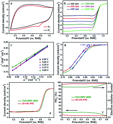
Initially, all the potentials in this work refer to that of reversible hydrogen electrode (RHE) could be converted from Hg/HgO electrode as E(RHE) = E(Hg/HgO) + 0.887 V (Fig. 4a). ORR activities of FeCo/NPC (T) electrocatalysts were measured in O2-saturated 0.1 M KOH aqueous solution. Fig. 4b showed that the current density (E < 0.7 V vs. RHE) in FeCo/NPC electrocatalysts increased significantly with the elevation of pyrolysis temperature from 600 °C to 900 °C. This might be explained that the increase of pyrolysis temperature was beneficial to enlarge the surface area of FeCo/NPC electrocatalysts (Table S1†), which finally led to the exposure of larger amount of active sites.9,33 It should be noted that the further increase of pyrolysis temperature from 900 °C to 1000 °C led to the decrease of current density. This might be caused by the shrinkage of carbon skeleton of FeCo/NPC at 1000 °C. Among these electrocatalysts, FeCo/NPC pyrolyzed at 900 °C exhibited the best ORR activity, and thus was selected for further electrochemical evaluation. Another investigation on the influence of molar ratio of Fe to Co on electrochemical performance of NNMEs was conducted in the O2-saturated 0.1 M KOH media (Fig. 4c). The E1/2 of Co, FeCo3, FeCo, Fe3Co, Fe, and commercial Pt/C were summarized in Table S2.† Compared with metal-free electrocatalyst, Co-based electrocatalyst displayed poor ORR performance, suggesting Co species probably just assist the doping of nitrogen to carbon lattice, but do not directly act as the active sites. It was apparent that the ORR activity of Fe based electrocatalysts were much superior to that of Co based electrocatalysts and metal-free electrocatalyst.19 Interestingly, if Fe and Co were simultaneously doped within the carbon matrix, the ORR performance in alkaline solution could be further boosted. The influence of hard-template MgO and carbon precursor adipic acid on ORR activity of FeCo/NPC (900) was also investigated in alkaline solution (Fig. 4d). The results showed that FeCo/NPC (900) was much more active than electrocatalysts without MgO as hard-template and electrocatalyst without adipic acid as carbon sources. Table S3† indicated that the use of MgO as the hard-template and adipic acid as carbon source was favorable to increase the BET surface area and thus expose more active sites.34,35
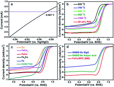 | ||
| Fig. 4 (a) LSV curves recorded at 25 °C in H2-saturated 0.1 M KOH media with a scanning rate of 1 mV s−1. The experiment was conducted with a platinum net as working electrode. The thermodynamic equilibrium potential for H+/H2 reaction.36 ORR polarization plots of (b) FeCo/NPC (T), (c) NNMEs with different molar ratio of Fe to Co and (d) FeCo/NPC (900), NNME prepared without MgO and NNME synthesized without adipic acid at the scanning rate of 5 mV s−1 in 0.1 M KOH solution. The rotation rate is 1600 rpm. | ||
In order to explain the excellent ORR activity of FeCo/NPC (900), cyclic voltammetry (CV) was conducted in N2- and O2-saturated alkaline solution. Compared with the CV curve in N2-saturated alkaline electrolyte, an obvious ORR peak happened at the potential of 0.735 V (vs. RHE, in Fig. 5a) with a high current density of 9.02 mA cm−2, highlighting the pronounced ORR activity in O2-saturated alkaline media. The ORR activity of FeCo/NPC (900) was confirmed by the RDE measurements with different rotation rates from 400 to 2025 rpm at the scanning rate of 5 mV s−1. The increasing rotation rates resulted in larger current density shown in Fig. 5b. Koutecky–Levich (K–L) plots with a good linear relationship were taken as the basic data for first-order reaction kinetics with respect to the dissolved O2 concentration.37 According to the data from Fig. 5c, the electrode transfer number (n) was calculated to be 3.90 in the potentials of 0.60, 0.65, 0.70, 0.75 and 0.80 V (vs. RHE) based on the eqn (1) and (2). This result showed that FeCo/NPC (900) favoured a four-electron ORR process. As evidenced by Eonset (Fig. 5d) and higher E1/2 (Fig. 5e), FeCo/NPC (900) were measured to be about 16 mV and 21 mV positive higher than those of commercial Pt/C (20 wt%, JM), respectively. To our knowledge, FeCo/NPC (900) with high Eonset (0.934 V vs. RHE) and E1/2 (0.865 V vs. RHE) displayed one of the best ORR performance in alkaline solution (Table S4†). In addition, the rotating ring disk electrode (RRDE) was further used to evaluate the ORR performance of FeCo/NPC (900) and commercial Pt/C (Fig. 5f). According to the eqn (3) and (4), the n value of 20 wt% Pt/C was calculated to be 3.98, and that of FeCo/NPC (900) was 3.82, similar to that of 3.90 calculated by K–L equation. This indicated that the ORR process on FeCo/NPC (900) was mainly conducted through a four-electron reduction pathway. The HO2−% yield of FeCo/NPC (900) was less than 11% over the potential range of 0.1 to 0.8 V (vs. RHE), slightly higher than that of commercial Pt/C.
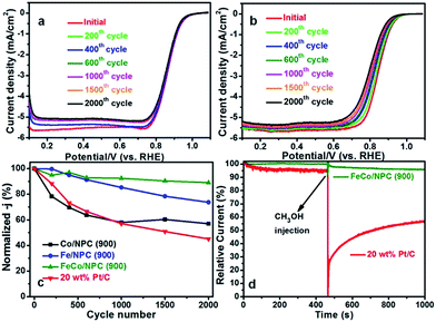
Furthermore, the accelerated durability test (ADT) of Co/NPC (900), Fe/NPC (900), FeCo/NPC (900) and 20 wt% Pt/C were assessed in O2-saturated 0.1 M KOH media (Fig. 6a and b and S3†). As shown in Fig. 6c, after 2000 cycles scanning from 0.487 to 1.087 V (vs. RHE), the normalized current density of Co/NPC (900), Fe/NPC (900) and FeCo/NPC (900) at 0.85 V (vs. RHE) decreased by 43.0%, 26.3%, 11.0%, while that of commercial Pt/C lost 54.9%. Such outstanding stability of FeCo/NPC (900) might be ascribed to the synergistic effect of Co and Fe, and the effective protection of Co and Fe based NPs by carbon layers against the leaching during the long term circumstance. On the other hand, methanol tolerance is another significant factor that will be required in the direct methanol fuel cells. As illustrated in Fig. 6d, FeCo/NPC (900) electrocatalyst displayed a perfect ORR selectivity in the alkaline solution in the presence of 10% (v/v) methanol injected at approximately 450 s. However, a dramatic decay of commercial Pt/C happened after the injection of methanol into alkaline solution, because of the vulnerability of Pt to methanol attack.
Conclusions
In summary, we have prepared novel FeCo/NPC electrocatalysts with hierarchical porous structures by employing MgO NPs as the hard-template. These NNME electrocatalysts exhibited superior ORR performance to the commercial Pt/C, high selectivity (n ≈ 4), excellent electrochemical stability and good tolerance to methanol in alkaline solution. The outstanding ORR activity of FeCo/NPC was possibly attributed to the large BET surface area, the hierarchical micro/meso/macroporous system, the synergism between Fe and Co based NPs embedded within carbon layers, and the N-doped carbon matrix. This study provides a novel synthesis method to prepare novel NNMEs with hierarchical porous structures for electrochemical devices, like alkaline fuel cells and chlor-alkali electrolysers.Conflicts of interest
There are no conflicts to declare.Acknowledgements
This work was financially supported by the Young Thousand Talents Program of China, the “Strategic Priority Research Program” of the Chinese Academy of Sciences (XDA09030103), the National Natural Science Foundation of China (Grant No. 21606219, 21473186, 21561024 and 21503081).References
- M. K. Debe, Nature, 2012, 486, 43–51 CrossRef CAS PubMed.
- X. Q. Huang, Z. P. Zhao, L. Cao, Y. Chen, E. Zhu, Z. Y. Lin, M. F. Li, A. M. Yan, A. Zettl and Y. M. Wang, Science, 2015, 348, 1230–1234 CrossRef CAS PubMed.
- D. S. Su and G. Q. Sun, Angew. Chem., Int. Ed., 2011, 50, 11570–11572 CrossRef CAS PubMed.
- A. Morozan, B. Jousselme and S. Palacin, Energy Environ. Sci., 2011, 4, 1238–1254 CAS.
- Y. Xie, C. Z. Tang, Z. Q. Hao, Y. Lv, R. X. Yang, X. M. Wei, W. Q. Deng, A. J. Wang, B. L. Yi and Y. J. Song, Faraday Discuss., 2014, 176, 393–408 RSC.
- E. Yeager, Electrochim. Acta, 1984, 29, 1527–1537 CrossRef CAS.
- R. Jasinski, Nature, 1964, 201, 1212–1213 CrossRef CAS.
- Y. Y. Liang, Y. G. Li, H. L. Wang, J. G. Zhou, J. Wang, T. Regier and H. J. Dai, Nat. Mater., 2011, 10, 780–786 CrossRef CAS PubMed.
- Z. S. Wu, S. B. Yang, Y. Sun, K. Parvez, X. L. Feng and K. Müllen, J. Am. Chem. Soc., 2012, 134, 9082–9085 CrossRef CAS PubMed.
- W. J. Jiang, L. Gu, L. Li, Y. Zhang, X. Zhang, L. J. Zhang, J. Q. Wang, J. S. Hu, Z. D. Wei and L. J. Wan, J. Am. Chem. Soc., 2016, 138, 3570–3578 CrossRef CAS PubMed.
- Z. Y. Wu, X. X. Xu, B. C. Hu, H. W. Liang, Y. Lin, L. F. Chen and S. H. Yu, Angew. Chem., Int. Ed., 2015, 127, 8297–8301 CrossRef.
- R. Liu, D. Q. Wu, X. L. Feng and K. Müllen, Angew. Chem., Int. Ed., 2010, 122, 2619–2623 CrossRef.
- S. Wang, E. Iyyamperumal, A. Roy, Y. H. Xue, D. S. Yu and L. M. Dai, Angew. Chem., Int. Ed., 2011, 123, 11960–11964 CrossRef.
- Y. Zheng, Y. Jiao, J. Chen, J. Liu, J. Liang, A. Du, W. M. Zhang, Z. H. Zhu, S. C. Smith and M. Jaroniec, J. Am. Chem. Soc., 2011, 133, 20116–20119 CrossRef CAS PubMed.
- J. Liang, Y. Jiao, M. Jaroniec and S. Z. Qiao, Angew. Chem., Int. Ed., 2012, 51, 11496–11500 CrossRef CAS PubMed.
- Y. Z. Su, Y. Zhang, X. D. Zhuang, S. Li, D. Q. Wu, F. Zhang and X. L. Feng, Carbon, 2013, 62, 296–301 CrossRef CAS.
- D. H. Deng, L. Yu, X. Q. Chen, G. X. Wang, L. Jin, X. L. Pan, J. Deng, G. Q. Sun and X. H. Bao, Angew. Chem., Int. Ed., 2013, 52, 371–375 CrossRef CAS PubMed.
- Y. Xie, H. Q. Li, C. Z. Tang, S. S. Li, J. Li, Y. Lv, X. M. Wei and Y. J. Song, J. Mater. Chem. A, 2014, 2, 1631–1635 CAS.
- G. Wu, K. L. More, C. M. Johnston and P. Zelenay, Science, 2011, 332, 443–447 CrossRef CAS PubMed.
- G. Wu, Z. W. Chen, K. Artyushkova, F. H. Garzon and P. Zelenay, ECS Trans., 2008, 16, 159–170 CAS.
- G. Wu, K. Artyushkova, M. Ferrandon, A. J. Kropf, D. Myers and P. Zelenay, ECS Trans., 2009, 25, 1299–1311 CAS.
- S. Gupta, D. Tryk, I. Bae, W. Aldred and E. Yeager, J. Appl. Electrochem., 1989, 19, 19–27 CrossRef CAS.
- M. Lefèvre, E. Proietti, F. Jaouen and J. P. Dodelet, science, 2009, 324, 71–74 CrossRef PubMed.
- Z. L. Li, G. L. Li, L. H. Jiang, J. L. Li, G. Q. Sun, C. G. Xia and F. W. Li, Angew. Chem., Int. Ed., 2015, 54, 1494–1498 CrossRef CAS PubMed.
- H. W. Liang, W. Wei, Z. S. Wu, X. L. Feng and K. Müllen, J. Am. Chem. Soc., 2013, 135, 16002–16005 CrossRef CAS PubMed.
- M. X. Li, Y. X. Yin, C. J. Li, F. Z. Zhang, L. J. Wan, S. L. Xu and D. G. Evans, Chem. Commun., 2012, 48, 410–412 RSC.
- Y. Jiang, Y. Xie, X. X. Jin, Q. Hu, L. Chen, L. Xu and J. H. Huang, RSC Adv., 2016, 6, 78737–78742 RSC.
- D. Eisenberg, W. Stroek, N. J. Geels, C. S. Sandu, A. Heller, N. Yan and G. Rothenberg, Chem.–Eur. J., 2016, 22, 501–505 CrossRef CAS PubMed.
- M. L. Xiao, J. B. Zhu, L. G. Feng, C. P. Liu and W. Xing, Adv. Mater., 2015, 27, 2521–2527 CrossRef CAS PubMed.
- W. N. Yan, W. Y. Bian, C. Jin, J. H. Tian and R. Z. Yang, Electrochim. Acta, 2015, 177, 65–72 CrossRef CAS.
- H. Xia, D. Zhu, Y. Fu and X. Wang, Electrochim. Acta, 2012, 83, 166–174 CrossRef CAS.
- J. Tang, T. Wang, R. R. Salunkhe, S. M. Alshehri, V. Malgras and Y. Yamauchi, Chem.–Eur. J., 2015, 21, 17293–17298 CrossRef CAS PubMed.
- A. G. Kong, X. F. Zhu, Z. Han, Y. Y. Yu, Y. B. Zhang, B. Dong and Y. K. Shan, ACS Catal., 2014, 4, 1793–1800 CrossRef CAS.
- J. Liang, Y. Zheng, J. Chen, J. Liu, D. Hulicova Jurcakova, M. Jaroniec and S. Z. Qiao, Angew. Chem., Int. Ed., 2012, 51, 3892–3896 CrossRef CAS PubMed.
- W. Wei, H. W. Liang, K. Parvez, X. D. Zhuang, X. L. Feng and K. Müllen, Angew. Chem., Int. Ed., 2014, 53, 1570–1574 CrossRef CAS PubMed.
- J. Y. Cheon, T. Kim, Y. M. Choi, H. Y. Jeong, M. G. Kim, Y. J. Sa, J. Kim, Z. H. Lee, T. H. Yang and K. Kwon, Sci. Rep., 2013, 3, 2715 CrossRef PubMed.
- Y. Zhang, X. D. Zhuang, Y. Z. Su, F. Zhang and X. L. Feng, J. Mater. Chem. A, 2014, 2, 7742–7746 CAS.
Footnote |
| † Electronic supplementary information (ESI) available. See DOI: 10.1039/c7ra09517a |
| This journal is © The Royal Society of Chemistry 2017 |

