
 Open Access Article
 This Open Access Article is licensed under a Creative Commons Attribution-Non Commercial 3.0 Unported Licence
Synthesis and NO2 gas-sensing properties of coral-like indium oxide via a facile solvothermal method
Haijiao Zhanga,
Xiumei Xu *ac,
Yongsheng Zhuab,
Keyan Baoa,
Zhiwen Lua,
Peng Sunb,
Yanfeng Sunb and
Geyu Lu*b
*ac,
Yongsheng Zhuab,
Keyan Baoa,
Zhiwen Lua,
Peng Sunb,
Yanfeng Sunb and
Geyu Lu*b
aCollege of Physics and Electronic Engineering, College of Chemistry and Pharmaceutical Engineering, Nanyang Normal University, Nanyang 473061, China
bState Key Laboratory on Integrated Optoelectronics, College of Electronic Science and Engineering, Jilin University, Changchun 130012, China
cCollaborative Innovation Centre of Chemistry for Life Sciences, School of Chemistry and Chemical Engineering, Nanjing University, 163 Xianlin Ave, 210023, Nanjing, China
First published on 23rd October 2017
Abstract
In this work, coral-like indium oxide was synthesized via an environmentally friendly one-step solvothermal method. The as-synthesized samples were characterized using X-ray powder diffraction (XRD), field emission scanning electron microscopy (FESEM), and transmission electron microscopy (TEM). The results indicate that the synthesized indium oxide nanorods were formed of nanoparticles. Moreover, the gas sensing properties of the coral-like products were investigated, and they exhibited high response and good selectivity to NO2.
1. Introduction
In recent years, with the acceleration of global industrialization and the increase of automobile ownership, more and more toxic, harmful, flammable and explosive gases have been discharged into the atmosphere. This threatens human life and the security of property, so gas sensors are urgently needed to monitor these gases in real time.1,2 There are various kinds of gas sensor, such as catalytic combustion type, photoionization, absorption spectrum infrared, solid electrolyte, and ultrasonic gas detectors. These detectors have the advantages of high resolution, wide detection range and long service life, but large and medium-sized instruments must be used which are demanding to the environment and relatively expensive. Sensors with real-time monitoring, portability, and agility have become the target of researchers. Due to their high sensitivity, quick response, small structure and easy integration, semiconductor sensors have become the focus of research in recent years.3 We mainly research semiconductor oxide gas sensors based on metal oxide semiconductors, such as SnO2,4–6 ZnO,7,8 WO3,9,10 Fe2O3,11,12 In2O3,13,14 CuO,15,16 and NiO.17The gas sensing properties of materials are not only dependent on the composition of diverse elements, but also the relationship with surface morphologies, architecture, particle size and shape. Various nanostructures have been successfully prepared by different methods, such as sputtering, evaporation–condensation, high-energy mechanical ball milling, vapor deposition, coprecipitation, sol–gel, and solid phase reaction methods. Now, more and more researchers are paying attention to one-dimensional materials because they have typical characteristics of nanoparticles (quantum size effect, small-size effect and surface effect), and unique thermal stability, electron transfer properties, photoconductivity, mechanical properties, optical properties, field emission effect, etc. One-dimensional materials have a variety of morphologies, including nanobelts, nanocables, nanodendrites, nanorods, nanotubes and multilevel structured nanofibers.
From the perspective of environmental protection and economic benefits, we hope that nanostructures can be prepared by moderate and low cost methods. As a very important wide-band-gap n-type semiconductor, indium oxide has been investigated for its gas sensitivity properties18 for CO,19,20 H2,21 VOCs,22 O3, Cl2, and NO2.23,24 In this paper, we report a facile method to prepare coral-like In2O3 by a solvothermal process without using any templates. The as-obtained coral-like In2O3 exhibited excellent gas sensitivity properties for NO2, and has potential application value for NO2 detection in an atmospheric environment.
2. Experimental
2.1. Synthesis and characterization of coral-like In2O3
All the reagents were used without any further purification. In a typical synthesis, 0.3536 g (1.2 mmol) of InCl3·4H2O was dissolved in 36 mL of ethanol, then 0.5 g (1.8 mmol) sodium dodecyl sulfonate and 0.4 g (6.7 mmol) urea were added into the transparent solution. After being stirred and subjected to ultrasound for 4 h, the formed micro-emulsion was transferred to a Teflon-lined stainless steel reaction kettle, sealed tightly, and maintained at 120 °C for 12 h. After the reaction kettle was cooled to room temperature naturally, the precipitate was washed with ethanol six times and then dried at 80 °C for 12 h. The precipitate was loaded into a porcelain boat which was placed in a muffle furnace. The furnace was slowly heated to a set temperature at a rate of 2 °C min−1 and then kept at that temperature for 2 h. After the furnace was cooled to room temperature, the faint yellow reaction products were collected.X-ray power diffraction (XRD) analysis was conducted on a Rigaku D/max-2500 X-ray diffractometer with Cu Kα1 radiation in the range of 20–70° (2θ) at a scanning rate of 12° min−1. The specific surface area was estimated using the Brunauer–Emmett–Teller (BET) equation based on the nitrogen adsorption isotherm obtained with a Micromeritics Gemini VII apparatus (Surface Area and Porosity System). The samples were degassed under vacuum at 200 °C for 4 h prior to the measurements. The pore size distribution was determined with the Barrett–Joyner–Halenda (BJH) method applied to the desorption branch of the adsorption–desorption isotherm. Field emission scanning electron microscopy (FESEM) images were recorded on a JEOL JSM-7500F microscope operating at 15 kV. Transmission electron microscopy (TEM), selected-area electron diffraction (SAED), and high-resolution transmission electron microscopy (HRTEM) measurements were obtained on a JEOL JEM-2100 microscope operated at 200 kV.
2.2. Fabrication and measurement of the sensor
The specific fabrication steps for the gas sensors are as follows: the faint yellow reaction product powders were mixed with ethanol to make a paste, which was coated onto an alumina tube to form a thin film. A pair of gold electrodes were installed at each end of the ceramic tube before it was coated with the paste; each electrode was connected with two Pt-wires. A Ni–Cr heating wire was inserted into the tube to form an indirectly-heated gas sensor. The structure of the sensor is shown in Fig. 1.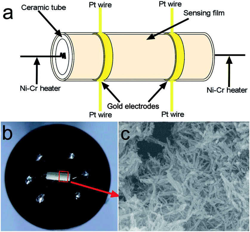 | ||
| Fig. 1 (a) Schematic image of the In2O3 sensor, (b) photograph and (c) SEM image of the In2O3 sensor. | ||
The gas-sensing properties of the samples were determined under laboratory conditions (50% ± 10% RH, 23 ± 1 °C). The measurement was processed by a static process in a test chamber. A given amount of the tested gas was injected into the test chamber, and the sensor was put into the chamber for the measurement of the sensing performance. Then the calculated amount of the target gas was injected into the chamber. When the response reached a constant value, the upper cover of the test chamber was removed and the sensor began to recover in air. The response of the sensor was defined as S = Rg/Ra for oxidizing gas or Ra/Rg for reducing gas, where Ra and Rg are the resistances of the sensor in the air and target gas, respectively. The response and recovery times are defined as the time taken by the sensor to achieve 90% of the total resistance change in the case of adsorption and desorption, respectively.
3. Results and discussion
3.1. Structural and morphological characteristics of the obtained In2O3
The TG-DSC method was executed to investigate the thermal behavior of the precursors in the temperature range 30–800 °C with a rate of 10 °C min−1 and their calcination temperatures were concluded from this method, as shown in Fig. 2. On the TG curve, the first weight loss of 0.56% between 30 °C and 140 °C (endothermic DSC peak at 98 °C) corresponds to the removal of water weakly adsorbed to the surface of the sample. The second weight loss step occurring between 140 °C and 550 °C (the endothermic DSC peak at 270 °C and predominantly exothermic DSC peak at around 500 °C) was assigned to the oxidative decomposition of the precursors leading to the formation of In2O3. The slight weak weight loss that occurs above 550 °C can be ascribed to the pyrolysis of organics adsorbed on the surface of the sample. After 550 °C, the weight loss does not change significantly, and the weight tends to be stable. Thus, the obtained sample was chosen to be sintered at 550 °C.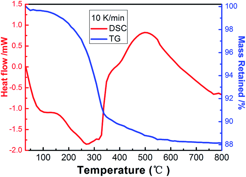 | ||
| Fig. 2 Thermogravimetric (TG) and differential scanning calorimetric (DSC) analysis curves of the as-prepared sample. | ||
Fig. 3 shows the X-ray powder diffraction (XRD) pattern of the as-synthesized In2O3 architecture. All of the diffraction peaks can be indexed to a pure rhombohedral structure of In2O3 according to JCPDS card no. 22-336, with the space group R![[3 with combining macron]](https://www.rsc.org/images/entities/char_0033_0304.gif) c (no. 167) and lattice parameters of a = 5.48 Å and c = 14.5 Å. The morphology of the samples was investigated by field emission scanning electron microscopy (FESEM).
c (no. 167) and lattice parameters of a = 5.48 Å and c = 14.5 Å. The morphology of the samples was investigated by field emission scanning electron microscopy (FESEM).
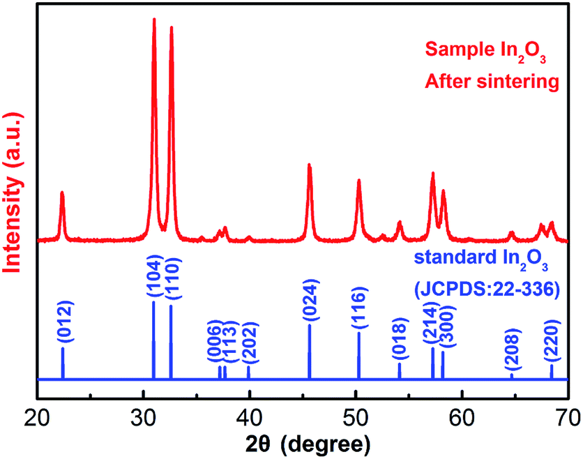 | ||
| Fig. 3 X-ray diffraction patterns of the as-prepared sample of In2O3. | ||
Fig. 4 shows typical FESEM images of the sample of In2O3 at different magnification. The low magnification SEM image shown in Fig. 4a reveals that the nanorods with a rough surface were 100 nm in length. No other morphologies could be detected, indicating a high yield of these structures. Fig. 4b shows the morphology of an individual rod in a higher-magnification FESEM image, indicating that such structures are constructed from nanoparticles. The EDX pattern of the product, shown in Fig. 4c, indicates that the prepared In2O3 is composed of only three elements: In, O, and Si (Si from the Si substrate used for measurement).
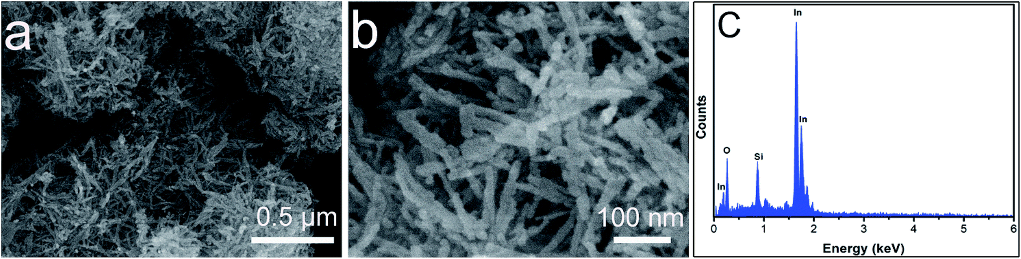 | ||
| Fig. 4 FESEM images (a and b) of the as-synthesized In2O3. The EDX pattern (c) of the coral-like In2O3. | ||
Further detailed structural analysis of the individual nanorods was carried out using TEM. Fig. 5 presents typical TEM images of the as-synthesized In2O3 nanorods, in accordance with the SEM images. As seen from the image, the thickness of the In2O3 nanorods was about 5–10 nm. The selected-area electron diffraction (SAED) pattern of an individual In2O3 nanorod (inset of Fig. 5a) confirms that the as-synthesized products were polycrystalline in structure. The high-resolution transmission electron microscopy (HRTEM) image (inset of Fig. 5b) shows a fringe distance of 0.288 nm, corresponding to the lattice distances of the (104) plane of hexagonal In2O3.
 | ||
| Fig. 5 Typical TEM images (a and b) of the In2O3 nanostructures. The corresponding SAED pattern (inset a). HRTEM image (inset b) taken from (a) and (b). | ||
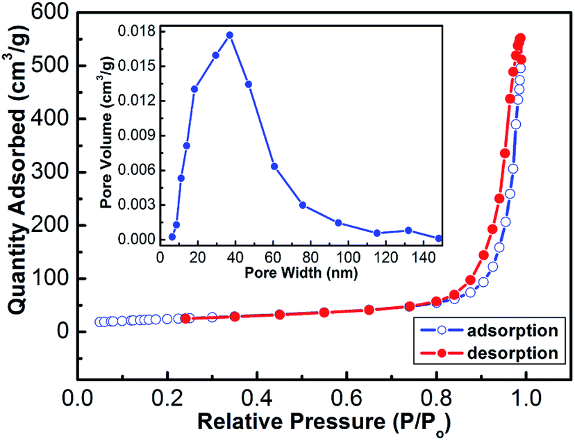
To further obtain information about the coral-like In2O3, nitrogen adsorption and desorption measurements were performed at 77 K. The representative N2 adsorption and desorption isotherm and the corresponding BJH pore size distribution plot (inset of Fig. 6) of the hierarchical microspheres are shown in Fig. 6. The BET surface area of the product was calculated to be 86.4 m2 g−1 with the Brunauer–Emmett–Teller (BET) method. The adsorption–desorption isotherms are typical type IV with a hysteresis loop according to the IUPAC classification, indicating that the powders contain disordered mesopores. Pore size distribution curves were calculated from the desorption branch of the nitrogen isotherm by the BJH method using the Halsey equation.
 | ||
| Fig. 6 Typical N2 adsorption–desorption isotherms of the In2O3 nanorods. The inset is the corresponding pore size distribution curve. | ||
To investigate the role of solvent in the formation of In2O3, controlled experiments of the process with different solvents were carried out by keeping other experimental conditions constant. When the experiments were performed with ethanol and ethylene glycol, coral-like nanostructures (Fig. 7a) and irregular microspheres (Fig. 7b) were obtained, respectively. The insets in (a) and (b) are the corresponding high-magnification FESEM images. Ethanol and ethylene glycol were used not only as solvents but also as surfactants, which could greatly affect the morphology and microstructure of the products.25,26 They can regulate the nucleation kinetics and growth of the products and efficiently control the morphology and structure of the final products.27
 | ||
| Fig. 7 FESEM images of In2O3 synthesized with different solvents: (a) ethanol and (b) ethylene glycol. | ||
3.2. Gas-sensing properties for NO2
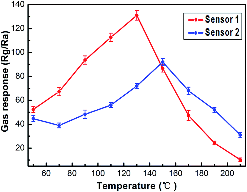
The gas sensing properties of the sensors based on the nanostructures obtained with ethanol and ethylene glycol (abbreviated to S1 and S2) were investigated. As is well known, the response of oxide semiconductors is highly influenced by the operating temperature.28In order to determine the optimum operating temperature, the responses of the sensors to 1 ppm of NO2 were tested at different temperatures from 50 °C to 210 °C. The relationship between the gas response and operating temperature is shown in Fig. 8. Obviously, sensor S1 showed a better gas response to 1 ppm of NO2 than sensor S2. The optimum operating temperatures of sensor S1 and sensor S2 are 130 °C and 145 °C, which were applied in the following investigations for sensor S1 and sensor S2. It can be obviously seen that the response of each sensor increases in the initial stage and decreases on further increasing the temperature.
 | ||
| Fig. 8 Response of the sensors to 1 ppm of NO2 as a function of operating temperature. | ||
Fig. 9a displays the real-time response curves of coral-like In2O3 (S1) to NO2 with concentrations varying from 50 ppb to 1 ppm. It can be seen that the gas response increased with increasing NO2 concentration. The resistances increased upon exposure to NO2, which is consistent with the gas sensing behavior of n-type oxide semiconductors. The functional relationship between the response of the sensor and the concentration of NO2 is shown in Fig. 9b. The detection limit of S1 is 10 ppb, and with increasing NO2 concentration S1 exhibited a superior response compared to S2. The coral-like In2O3 nanostructure sensor shows an acceptable response from the view of practical application. When the sensor was exposed to 10 ppb NO2, the response value was 2.41. The response value was about 4.35, 6.5, 8.9, 13.5, 18.2, 24.5, 43.8, 98 and 132 to 20, 30, 40, 50, 100, 200, 300, 500 and 1000 ppb NO2, respectively.
 | ||
| Fig. 9 (a) The response transients of S1 to different NO2 concentrations. (b) Gas response of the sensors as a function of NO2 concentration (inset of (b) is the gas response of S1 from 10 ppb to 50 ppb). | ||
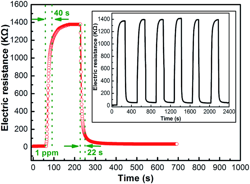
The response transient curve of the coral-like In2O3 nanostructure sensor to 1 ppm NO2 was measured at 130 °C (Fig. 10), and the response time and recovery time were about 40 s and 22 s, respectively. The six reversible cycles of the response curve indicate a stable and repeatable response characteristic, as shown in the inset of Fig. 10.
 | ||
| Fig. 10 Response transient curve and (inset) the repeated response transient curves to 1 ppm NO2 for the sensor at 130 °C. | ||
A comparison between the sensing performances of the sensor and those in literature reports29–35 is summarized in Table 1. From the table, it can be observed that the sensor based on the coral-like In2O3 nanostructures has a correspondingly higher gas response and lower working temperature. Fig. 11 shows the response of the sensors using coral-like In2O3 to various target gases. All of the gases were tested at an operating temperature of 130 °C with a concentration of 1 ppm. It can be clearly seen that the sensor based on coral-like In2O3 exhibited the highest response to NO2 and negligible responses to other gases. Furthermore, good long-term stability was also a key parameter determining whether gas sensors could detect accurately in practical use or not. As shown in Fig. 12, there was no obvious variation among the values of resistance in air at 130 °C and their corresponding gas responses to 1 ppm NO2 in the 30 days of testing, which meant that the coral-like In2O3 gas sensor had reliable and good long-term stability.
| Sensing materials | NO2 concentration (ppm) | Working temperature (°C) | Sensor response | Reference |
|---|---|---|---|---|
| In2O3 nanosheets | 5 | 250 | 42 | 29 |
| In2O3-based micro | 1 | 275 | 8 | 30 |
| SnO2 nanowires | 1 | 200 | 20 | 31 |
| ZnO nanoflowers | 1 | 174 | 14 | 32 |
| ZnO nanorods | 1 | 150 | 6 | 33 |
| WO3 film | 0.5 | 100 | 11 | 34 |
| WO3 nanocrystals | 3 | 150 | 13 | 35 |
| Coral-like In2O3 | 0.5 | 130 | 98 | Present work |
 | ||
| Fig. 11 Cross-responses of the sensor to various test gases at 130 °C. | ||
 | ||
| Fig. 12 (a) Resistances in air and (b) responses to 1 ppm NO2 of the coral-like In2O3 sensor as a function of the days of testing at 130 °C. | ||
The NO2 sensing mechanism can be described by the following equations:36–38
| NO2(gas) + e− → NO2−(ads) | (1) |
| NO2(gas) + 2O−(ads) → NO2−(ads) + O2(gas) + e− | (2) |
| NO2(gas) + O−(ads) → NO+(ads)+ 2O−(ads) | (3) |
Compared with sensor 2, the excellent gas sensitivity of coral-like In2O3 (sensor 1) can be attributed to the abundant framework of gas diffusion and chemical adsorption as well as the reaction on the surface of the indium trioxide material.39 The network of pores of the coral-like structure enables gas to diffuse easily to the surface of In2O3. Therefore, the sensor has a high response to NO2. Thus the novel coral-like In2O3 can be used as a promising sensing material.
4. Conclusion
In summary, coral-like In2O3 was successfully synthesized by a solvothermal method, after calcination of the precursor at 550 °C for 2 h. Field emission scanning electron microscopy and transmission electron microscopy show that the coral-like In2O3 was composed of nanorods. The gas sensing properties of sensors based on the as-synthesized In2O3 towards NO2 were investigated. The sensor exhibits excellent NO2 sensing properties at 130 °C. The sensor response is about 2.41 to 10 ppb NO2 at 130 °C. The response time and recovery time were about 40 s and 22 s, respectively. These results suggest that our sensor might have potential application in the fabrication of highly sensitive and low power consumption NO2 gas sensor devices.Conflicts of interest
There are no conflicts to declare.Acknowledgements
This work is supported by the National Natural Science Foundation of China (61473132, 61474057, 11504131, 11504188 and 61703216), “863” High Technology Project (2013AA030902 and 2014AA06A505), school-based program of Nanyang Normal University (QN2016017 and QN2017054), Henan Province Department of Education Project (No. 17A510003 and 16HASTIT010), Henan Joint Funds of the National Natural Science Foundation of China (U1404608, U1404216, U1404505 and U1504626), and Innovation Scientists and Technicians Troop Construction Projects of Henan Province (No. C20150029).References
- G. B. Hamra, F. Laden, A. J. Cohen, O. Raaschou-Nielsen, M. Brauer and D. Loomis, Environ. Health Perspect., 2015, 123, 1107–1112 CrossRef PubMed.
- K. Ram, M. Sarin, A. Sudheer and R. Rengarajan, Aerosol Air Qual. Res., 2012, 12, 359–370 CAS.
- N. Yamazoe and K. Shimanoe, Sens. Actuators, B, 2009, 138, 100–107 CrossRef CAS.
- C. Xu, J. Tamaki, N. Miura and N. Yamazoe, Sens. Actuators, B, 1991, 3(2), 147–155 CrossRef CAS.
- M. Law, H. Kind and B. Messer, Angew. Chem., Int. Ed., 2002, 114(13), 2511–2514 CrossRef.
- M. Poloju, N. Jayababu, E. Manikandan and M. V. R. Reddy, J. Mater. Chem. C, 2017, 5, 2662–2668 RSC.
- X. F. Pan, X. J. Zhao, J. Q. Chen, A. Bermak and Z. Y. Fan, Sens. Actuators, B, 2015, 206, 764–771 CrossRef CAS.
- Y. Xia, J. Wang, J. L. Xu, X. Li, D. Xie, L. Xiang and S. Komarneni, ACS Appl. Mater. Interfaces, 2016, 8, 35454–35463 CAS.
- M. Akiyama, J. Tamaki, N. Miura and N. Yamazoe, Chemistry Letters, 1991, 20, 1611–1614 CrossRef.
- S. Ashraf, C. S. Blackman, R. G. Palgrave, S. C. Naisbitt and I. P. Parkin, J. Mater. Chem., 2007, 17, 3708–3713 RSC.
- L. P. Zhu, N. C. Bing, L. L. Wang, H. Y. Jin, G. H. Liao and L. J. Wang, Dalton Trans., 2012, 41, 2959–2965 RSC.
- B. Zhang, J. Liu, X. B. Cui, Y. L. Wang, Y. Gao, P. Sun, F. M. Liu, K. Shimanoe, N. Yamazoe and G. Y. Lu, Sens. Actuators, B, 2016, 241, 904–914 CrossRef.
- D. H. Zhang, Z. Q. Liu, C. Li, T. Tang, X. L. Liu, S. Han, B. Lei and C. W. Zhou, Nano Lett., 2004, 4, 1919–1924 CrossRef CAS.
- S. Park, G. J. Sun, H. Kheel, I. L. Wan, S. Lee, S. B. Choid and C. Lee, Sens. Actuators, B, 2016, 227, 591–599 CrossRef CAS.
- L. A. Patil and D. R. Patil, Sens. Actuators, B, 2006, 120, 316–323 CrossRef CAS.
- J. P. Liu, X. T. Huang, Y. Y. Li, Z. K. Li, Q. B. Chi and G. Y. Li, Solid State Sci., 2008, 11, 1568–1576 CrossRef.
- S. L. Xiong, C. Z. Yuan, X. G. Zhang and Y. T. Qian, CrystEngComm, 2011, 13, 626–632 RSC.
- M. Liess, Thin Solid Films, 2002, 410, 183–187 CrossRef CAS.
- N. Singh, C. Yan and P. S. Lee, Sens. Actuators, B, 2010, 150, 19–24 CrossRef CAS.
- K. L. Sang, S. H. Hwang, D. Chang and S. Kim, Sens. Actuators, B, 2010, 149, 28–33 CrossRef.
- A. Qurashi, T. Yamazaki, E. M. El-Maghraby and T. Kikuta, Appl. Phys. Lett., 2009, 95(15), 083124 CrossRef.
- R. Q. Xing, L. Xu, J. Song, C. Y. Zhou, Q. L. Li, D. L. Liu and H. W. Song, Sci. Rep., 2015, 5, 10717 CrossRef CAS PubMed.
- P. C. Xu, Z. X. Cheng, Q. Y. Pan, J. Q. Xu, Q. Xiang, W. J. Yu and Y. L. Chu, Sens. Actuators, B, 2008, 130, 802–808 CrossRef CAS.
- F. Gu, R. Nie, D. Han and Z. Wang, Sens. Actuators, B, 2015, 219, 94–99 CrossRef CAS.
- C. M. Zhang, C. X. Li, C. Peng, R. T. Chai, S. S. Huang, D. M. Yang, Z. Y. Cheng and J. Lin, Chem.–Eur. J., 2010, 16, 5672–5680 CrossRef CAS PubMed.
- R. Jin, Y. Xu, G. Li, J. Liu and G. Chen, Int. J. Hydrogen Energy, 2013, 38(22), 9137–9144 CrossRef CAS.
- H. X. Dong, Z. H. Chen, L. X. Sun, L. Zhou, Y. J. Ling, C. Z. Yu, H. Hoe Tan, C. Jagadish and X. C. Shen, J. Phys. Chem. C, 2009, 113, 10511–10516 CAS.
- T. M. E. Franke, T. J. Koplin and U. Simon, Small, 2006, 2, 36–50 CrossRef PubMed.
- L. P. Gao, Z. X. Cheng, Q. Xiang, Y. Zhang and J. Q. Xu, Sens. Actuators, B, 2015, 208, 436–443 CrossRef CAS.
- B. J. Kim, I. G. Song and J. S. Kim, Electron. Mater. Lett., 2014, 10, 509–513 CrossRef CAS.
- S. W. Choi, S. H. Jung and S. S. Kim, J. Hazard. Mater., 2016, 665, 173–179 Search PubMed.
- J. Li, W. G. Zhang and J. B. Sun, Ceram. Int., 2016, 42, 9851–9857 CrossRef CAS.
- D. V. Ponnuvelu, B. Pullithadathil, A. K. Prasad, S. Dhara, A. Ashok, K. Mohamed, A. K. Tyagi and B. Raj, Appl. Surf. Sci., 2015, 355, 726–735 CrossRef CAS.
- T. Tesfamichael, C. Piloto, M. Arita and J. Bell, Sens. Actuators, B, 2015, 221, 393–400 CrossRef CAS.
- Z. H. Wang, M. Hu, Y. F. Wang, X. C. Liu and Y. X. Qin, J. Alloys Compd., 2016, 665, 173–179 CrossRef CAS.
- N. Yamazoe and K. Shimanoe, Sens. Actuators, B, 2010, 150, 132–140 CrossRef CAS.
- C. S. Rout, K. Ganesh, A. Govindaraj and C. N. R. Rao, Appl. Phys. A: Mater. Sci. Process., 2006, 85, 241–246 CrossRef CAS.
- N. Barsan, D. Koziej and U. Weimar, Sens. Actuators, B, 2007, 121, 18–35 CrossRef CAS.
- P. Sun, C. Wang, X. Zhou, P. F. Cheng, K. Shimanoe, G. Y. Lu and N. Yamazoe, Sens. Actuators, B, 2014, 193, 616–622 CrossRef CAS.
| This journal is © The Royal Society of Chemistry 2017 |