
 Open Access Article
 This Open Access Article is licensed under a Creative Commons Attribution-Non Commercial 3.0 Unported Licence
Speed dependence of liquid superlubricity stability with H3PO4 solution†
Chen Xiaoa,
Jinjin Lib,
Lei Chena,
Chenhui Zhangb,
Ningning Zhouc,
Linmao Qian *a and
Jianbin Luob
*a and
Jianbin Luob
aTribology Research Institute, State Key Laboratory of Traction Power, Southwest Jiaotong University, Chengdu 610031, Sichuan, China. E-mail: linmao@swjtu.edu.cn; Tel: +86-28-87600687
bState Key Laboratory of Tribology, Tsinghua University, Beijing 100084, China
cBeijing Key Laboratory of Long-life Technology of Precise Rotation and Transmission Mechanisms, Beijing Institute of Control Engineering, Beijing 100094, China
First published on 23rd October 2017
Abstract
In the present study, the speed dependence of liquid superlubricity stability with phosphoric acid (H3PO4) solution was studied. Achieving superlubricity with H3PO4 solution is the result of the formation of a hydrated water layer with low shear strength combined with the hydrodynamic effect. The experimental results show that the superlubricity stability of a Si3N4/glass pair with H3PO4 solution strongly depends on speed and stable superlubricity is achievable when speed ranges from 0.075 m s−1 to 0.209 m s−1 under given loading conditions. Superlubricity failure under low speed is mainly attributed to the weak hydrodynamic effect. However, when the speed is too high, the hydrated water layer can hardly form due to the insufficient running-in process and serious substrate damage. Based on these results, a method was proposed to promote the achievable speed of stable superlubricity to m s−1 level, namely performing the pre-running-in process under low or medium speed and then running at high speed. The results may help understand the liquid superlubricity failure mechanism and open a door to the wide application of liquid superlubricity in industrial areas.
Introduction
The concept of superlubricity was proposed by Hirano and Shinjo in the 1900s. Since then, superlubricity has attracted considerable attention because of the strong demand for energy saving, emission reduction and excellent lubricant performance in the mechanical industry.1,2 Superlubricity is used to describe the physical phenomenon of an ultra-low friction coefficient (near zero) between two contacting surfaces. However, the judging boundary of superlubricity increases to 0.01 because of limitations in measuring precision and other factors in actual experimental conditions.3–5 Given that the superlubricity behavior is strongly restricted by the requirement of working conditions, hardly any of the superlubricity achieved in a laboratory environment can be applied in industrial activities.In the past few years, several superlubricity systems have been reported. Superlubricants can be simply divided into solid and liquid. Solid lubricants mainly include diamond-like carbon, molybdenum disulphide, graphite and CNx films.6–11 Liquid lubricants mainly include ceramic material with water, polymer brushes, glycerol solution with acid or polyhydric alcohol and polysaccharide mucilage from plants.12–16 Water-based solutions are one of the most promising liquid superlubricants because they are low-cost, highly reproducible and environment friendly.17 However, the speed achieved superlubricity in the past studies were mostly in a low level (∼mm s−1) which is considerably lower than that in actual industry productions, such as the working speed of ceramic bearing in actual running conditions (∼m s−1).18 Stable superlubricity with long working life achieved at high speed remains a serious challenge in industrial applications of superlubricity systems.
Recently, Li et al. reported that Si3N4/glass pair with H3PO4 solution resulted in an ultra-low friction coefficient of 0.004 after two steps of running-in process.19 Further studies showed that superlubricity mechanism was mainly attributed to the formation of a three-layer water-containing nanofilm with hydrogen bond network (hydrated water layer) between two contacting surfaces after the tribochemical reaction between acid solution and tribopair surfaces during the running-in process.20–22 The special composite lubricating nanofilm can effectively separate the tribopair surfaces and provide a hydrated water layer with ultra-low shear strength instead of a direct frictional contact. Meanwhile, the influences of the types of acid, hydrogen ion concentration and volume of lubricant on the superlubricity behavior of Si3N4/glass pair have also been studied.19,23–25 Moreover, friction force and wear between the moving contacting parts usually increase dramatically and further induce equipment failure because of the excessive impact force and system instability under high working speed.26 Until recently, few investigations have focused on the speed capacity of phosphoric acid superlubricity system, especially the superlubricity stability under high speed. Therefore, to understand the superlubricity failure mechanism and promote their applications in practical industrial activities, it is essential to investigate the effect of speed on the superlubricity stability of Si3N4/glass pair with H3PO4 solution.
In this study, the superlubricity stability of Si3N4/glass pair with H3PO4 solution was investigated at various speeds. It is found that the superlubricity stability strongly depends on speed, and stable superlubricity could be achieved only when the speed ranges from 0.075 m s−1 to 0.209 m s−1 under given loading conditions. Failure under low and high speeds may be attributed to the absence of either hydrodynamic effect or hydrated water layer. Based on these results, a stable superlubricity state could be acquired under high speed after pre-running-in process under low or medium speed.
Experimental materials and methods
The H3PO4 solution used in all friction tests was a commercial product purchased from Sinopharm Chemical Reagent Co., Ltd. Its mass fraction is about 85 wt% and the purity is larger than 99%. It was diluted with deionized water to a pH value of 1.5, and the corresponding mass fraction of phosphoric acid solution was about 0.3 wt%. The upper sample was a Si3N4 ball with a diameter of 4 mm (Shanghai Unite Technology Co., Ltd), and the substrate was a glass slide with a root-mean-square (RMS) roughness of about 0.5 nm over a 400 μm2 area. Before friction tests, both Si3N4 balls and glass slides were ultrasonically cleaned in methanol, ethanol and deionized (DI) water for 10 min in sequence to remove surface contamination, and then dried by pure nitrogen gas.All the friction tests were performed by a universal micro-tribotester (UMT-3, Bruker, USA) with ball-on-disk mode, as illustrated in Fig. 1. A drop (10 μL) of H3PO4 solution was added between the Si3N4 ball and glass substrate before tests. The applied normal load was 3 N, which provided a maximum contact pressure of 830 MPa based on the Hertzian contact theory.27 The rotation speed of the glass substrate was varied from 100 rpm to 1500 rpm, and the corresponding linear speed was calculated from 0.042 m s−1 to 0.628 m s−1 with a track radius of 4 mm. During the tests, the temperature was controlled at 25 ± 2 °C and the relative humidity was about 60%. In order to ensure the measurement accuracy of friction, the measurement errors could be reduced significantly by pre-commission. More details about this process have been described in previous literature.28 The macro-topographies of the wear tracks were observed by white light interferometer (MFT-3000, Rtec, USA) and optical microscope (BX60M, Olympus, Japan). The microstructures and RMS in the wear tracks of glass substrates were measured by an atomic force microscope (AFM, SPI3800N, Seiko Instruments Inc., Japan), using a silicon nitride probe (MLCT, Veeco, USA) with a curvature radius of approximately 15 nm and spring constant of around 0.1 N m−1. The element compositions of wear scar on glass surface after the friction test at 0.628 m s−1 was also characterized by energy disperse spectroscopy (EDS, SEM, EVO18, ZEISS, Germany).
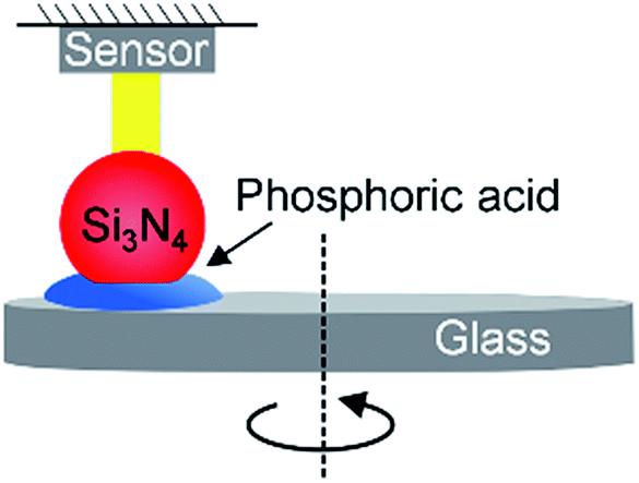 | ||
| Fig. 1 The schematic illustration of friction measurement system with ball-on-disk mode. The tribopair samples are Si3N4 ball and glass slide, and the lubricant is a drop (10 μL) of H3PO4 solution (pH = 1.5). | ||
Results
Speed dependence of friction coefficient of Si3N4/glass pair
Fig. 2 shows the measured friction coefficient of Si3N4/glass pair with H3PO4 solution under five different speeds. When the speed is lower than 0.075 m s−1, the friction coefficient decreases from 0.5 to 0.04 after a running-in period of 400 s and then stabilizes. This result indicates that superlubricity is unachievable under this speed. However, when the speed increases to 0.075 m s−1, the friction coefficient decreases to less than 0.01 after a running-in period of 300 s and the superlubricity state remains stable during the entire experiment period. The friction coefficient decreases from 0.008 to 0.005 with the increase in speed from 0.075 m s−1 to 0.209 m s−1. Meanwhile, the sliding time of the running-in process before superlubricity is achieved decreases along with the increase in speed. When the speed further increases to 0.334 m s−1, the friction coefficient decreases to 0.04 gradually during the running-in process and then increases sharply to lubrication failure. The evolution of friction coefficient with time under 0.628 m s−1 is similar with the result under 0.334 m s−1, however, the time for lubrication failure is shorter.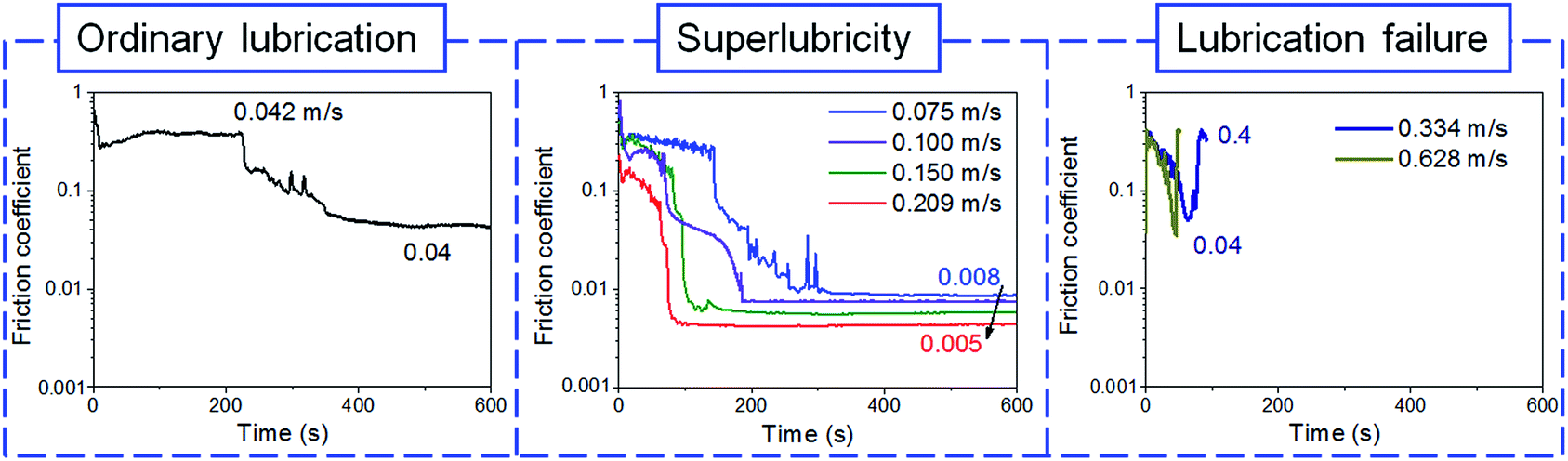 | ||
| Fig. 2 Friction coefficient of Si3N4/glass pair under various speeds. The applied load is 3 N. | ||
Based on the above friction results, it is found that the superlubricity behavior strongly depends on speed, and the lubrication system with H3PO4 solution could not achieve superlubricity and even lead to lubrication failure at high speed. The relationship between the final friction state and speed is shown in Fig. 3. It can be seen that with the increase in speed, the friction coefficient initially decreases, reaches a minimum value and eventually increases. The speed for superlubricity achieved within 600 s ranges from 0.075 m s−1 to 0.209 m s−1. When the speed is lower than 0.075 m s−1, the final friction coefficient ranges from 0.01 to 0.05 (in ordinary lubrication state). In both cases, lubrication states including ordinary lubrication and superlubricity are stable until the end of the tests. When the speed is higher than 0.334 m s−1, the friction coefficient experiences a short instability period of ordinary lubrication and then enters into lubrication failure. In these cases, superlubricity is unachievable and even ordinary lubrication state is unstable.
 | ||
| Fig. 3 Variation of the final friction coefficients of Si3N4/glass pairs with sliding speeds. The dashed line was fitted by B-spline based on the experimental points. | ||
Speed dependence of surface damage of Si3N4/glass pair
Previous studies have shown that the wear behavior of tribopair is closely related to interfacial friction behavior.29–32 To examine the effect of speed on the friction behavior of Si3N4/glass pair lubricated with H3PO4 solution, the surface damage of Si3N4 balls and glass substrates were characterized by the white light interferometer. Fig. 4 and 5 display the optical images and line profiles of the wear tracks on glass substrates and Si3N4 balls. The wear rates of Si3N4/glass pair as a function of speed are shown in Fig. 6. All wear scars under various speeds were obtained after the same sliding distance of 30 m. These results reveal that wear behavior also strongly depends on speed and the trend is consistent with the friction results. When the speed is less than 0.075 m s−1, the wear depth of glass substrate and ball is approximately 1 μm and 2.2 μm, respectively. When the speed increases to 0.209 m s−1, the friction state enters into superlubricity and the depth of wear scars on glass substrate and Si3N4 ball decreases to 0.55 μm and 1.3 μm, respectively. When the speed exceeds 0.334 m s−1, lubrication failure occurs and tribopair wear begins to increase.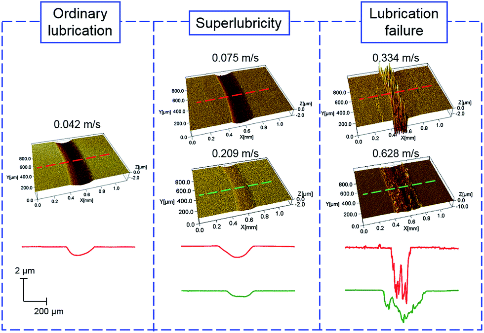 | ||
| Fig. 4 Comparison of optical images and line profiles of glass surfaces after the tests under various speeds. The sliding distance is 30 m. | ||
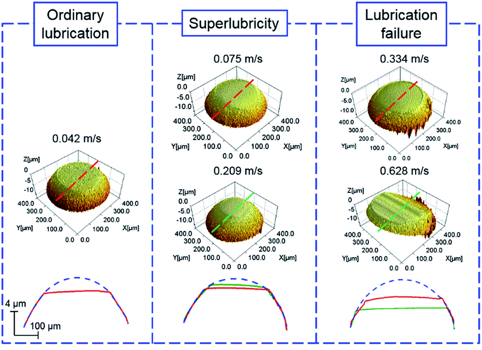 | ||
| Fig. 5 Comparison of optical images and line profiles of Si3N4 surfaces after the tests under various speeds. The sliding distance is 30 m. | ||
 | ||
| Fig. 6 Comparison of wear rate of glass surfaces (a) and Si3N4 balls (b) after the tests under various speeds. The dashed line was fitted by B-spline based on the experimental points. | ||
Moreover, the wear rates of Si3N4 balls are found to be lower than those of glass substrates under all speeds. Notably, all the wear scars on Si3N4 balls are smooth and experience little slight variations under different speed tests. However, the differences on the glass surfaces are significant and the surface roughness of wear areas under high speed is considerably rougher than that under low speed. The differences in surface topographies of ball and substrate may be resulted from the great discrepancies in mechanical properties and wear resistance. For example, the hardness of Si3N4 (∼35 GPa) is considerably larger than that of glass (∼7 GPa).33 Considering that the thermal stability and mechanical properties of Si3N4 ball are much better than those of glass, the stronger impact force with the increase in speed induces severe surface damage for the fragile glass substrate. However, a slighter wear and smoother wear area can be produced on the Si3N4 surface. In addition, the wear debris produced in the sliding process may also aggravate the destruction of glass surface. Therefore, the lubrication state will be mostly influenced by the surface roughness of wear scars on glass substrates rather than those of Si3N4 balls.
To further analyze the surface damage under various speeds, the microstructures of sliding tracks on glass substrates were scanned by AFM. Fig. 7 shows the typical surface topographies and RMS roughness (over 100 μm2) of the sliding tracks after the running-in period. In the superlubricity state, large smooth contact areas are observed in the wear area of glass substrate, and surface damage mainly consists of pressure pits and slight scratches. However, under lubrication failure state, the substrate surfaces are severely damaged and the RMS roughness (0.25–0.35 μm) increases by more than 10-fold compared with those rubbed at low and medium speeds (0.015–0.025 μm). Based on the theoretical calculation in previous studies, when stable superlubricity is achieved, the lubricating film thickness between Si3N4 ball and glass substrate is approximately dozens of nanometers, which is also plotted in Fig. 7 for comparison.22 Obviously, the theoretical lubricating film thickness is close to the roughness of superlubricity surface and considerably smaller than that of failure surface.
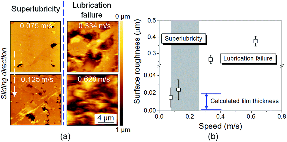 | ||
| Fig. 7 (a) Typical AFM images of the wear tracks on glass substrates after the running-in process under various speeds, and the white dashed line showing the sliding direction of Si3N4 ball. (b) Comparison of the surface roughness of the wear tracks on glass surfaces after the running-in process under various speeds. All the samples were ultrasonically cleaned in ethanol and deionized water for 10 min before the RMS measurements. | ||
Discussion
Superlubricity failure mechanism under low and high speeds
In order to verify the lubrication failure mechanism at high speed, the surface topographies of glass substrates after the high- and medium-speed running-in process were observed using an optical microscopy. Fig. 8a shows the optical images of glass after the running-in process under the sliding speed of 0.628 m s−1 before and after cleaning. At this moment, the friction coefficient begins to increase from the bottom of the friction curve. The wear track is covered with a layer of residual lubricating film which is dried to lumps obviously, and several lubricating film fragments scatter around the runway. Moreover, the glass substrate after ultrasonic cleaning using ethanol and deionized water shows the actual wear area. It is found that the contact area in the wear track looks smooth because the surface damage may be filled with the dehydrated lubricating film. In comparison with the severely damaged substrate surface under high speed, the main damage of the wear area run under medium speed is only some slight scratched marks, as shown in Fig. 8b. When the speed ranges from 0.075 m s−1 to 0.209 m s−1, the lubricant solution is volatilizing moisture continually due to the frictional heat in the running-in process and in equilibrium with the moisture in the air while the stable superlubricity behavior is achieved. As displayed in the optical image of uncleaning glass substrate, the sliding track was covered by the adsorbed liquid film completely. It can be speculated that the lubrication failure at high speed is attributed to the acceleration of the evaporation of free water in the sliding interface during the friction process. Once the water evaporation rate is sufficiently high to exceed the limit of the liquid system, the lubricating film may be destroyed and lubrication failure occurs. The surface morphology and element compositions of wear scar after the running-in procedure at 0.628 m s−1 and original surface were also characterized by SEM and EDS. Before the EDS detection, the surface was rinsed by plentiful DI water to eliminate the influence of liquid lubricating film. The EDS results (Fig. S1 of ESI†) showed that no obvious difference was identified between worn surface and original surface in the elemental compositions. | ||
| Fig. 8 Uncleaning (I) and cleaning (II) glass surface after running-in process under the speed (a) v = 0.628 m s−1 (lubrication failure) and (b) v = 0.075 m s−1 (stable superlubricity). | ||
Friction tests were also conducted at medium speed after the running-in process with various speeds to verify the effect of surface damage on superlubricity failure, as shown in Fig. 9. The other experimental parameters are the same as the tests in Fig. 2. At low-speed running-in case, ordinary lubrication is achieved after 300 s running process and friction coefficient cannot further decrease (Fig. 2). However, when the speed increases to 0.125 m s−1, superlubricity state is achieved suddenly without a running-in period and then remains stable until the end of the test. For comparison, the test is stopped when the lubrication system undergoes ordinary lubrication state after high-speed running-in process and the friction coefficient has no sign of increasing at this moment. Subsequently, the test restarts under the speed of 0.125 m s−1. The friction coefficient suddenly decreases to a low value of approximately 0.023 and then stabilizes until the end of the test. In this case, stable ordinary lubrication state caused by the reduction of speed replaces the lubrication failure phenomenon in Fig. 2, but still fails to achieve stable superlubricity. The results indicate that excessive moisture loss in the lubricating film during the high-speed process is not the only factor influencing lubrication instability, and other factors influencing the realization of the stable superlubricity state also exist.
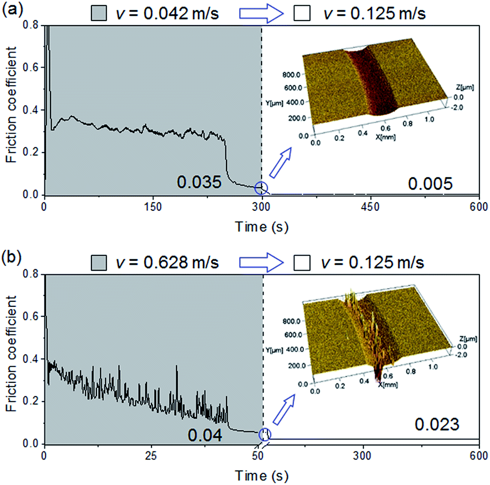 | ||
| Fig. 9 Friction coefficient with time under the lubrication of H3PO4 solution after the running-in process under low speed (a, 0.042 m s−1) and high speed (b, 0.628 m s−1), the insets are the corresponding optical images of glass surfaces after the running-in process. | ||
Previous studies have indicated that the superlubricity achieved under medium speed may be attributed to a thin film with hydrogen bond network among H3PO4, H2PO4− and H2O that are absorbed on the stern layer. This process is induced by hydrogen ions after the free water in the liquid lubricant decreases to a constant value.19 The special composite lubricating nanofilm is the core difference between H3PO4 and other acids that can only achieve ordinary lubrication state.23 Moreover, the sliding of two surfaces with each other results in a hydrodynamic effect in the limited hydrated water layer, which also plays an important role in the lubrication state of the liquid system.21 The hydrodynamic effect in the contact area significantly weakens with the decrease in speed. The subdued lubricating film can barely support the high contact pressure from the upper Si3N4 ball and results in the direct solid–solid contact of tribopair surfaces, thereby failing to achieve superlubricity state. In addition, due to the short and insufficient running-in process under high speed, the tribopair surfaces can be inferred to be separated quickly by H3PO4 molecular layer before the formation of the special hydrated water layer. Given the large friction force and great heating efficiency at high-speed running-in process, serious substrate damage and probable temperature increase may cause excessive moisture loss, which eventually results in lubrication failure. Therefore, the stable superlubricity of H3PO4 system is the result of the formation of hydrated water layer combined with the hydrodynamic effect. As shown in Table 1, here we proposed that superlubricity failure under low and high speeds may be attributed to the absence of either hydrodynamic effect or hydrated water layer. Moreover, the high-speed induced superlubricity failure of Si3N4/glass pair with H3PO4 solution provides the following two critical insights into the failure mechanism created by the failed formation of the hydrated water layer: (I) the serious surface damage on glass substrate results in the superlubricity failure by restricting the formation of a uniform and effective liquid lubricating layer; (II) excessive moisture loss destroys lubricating film, which causes lubrication failure.
| Sliding velocity v (m s−1) | Hydrodynamic effect | Hydrated water layer | Lubrication state |
|---|---|---|---|
| v < 0.075 | ✗ | ✓ | Ordinary lubrication |
| 0.075 < v < 0.209 | ✓ | ✓ | Superlubricity |
| v > 0.209 | ✓ | ✗ | Lubrication failure |
High-speed superlubricity achieved after low- or medium-speed running-in process
Friction reduction will greatly save energy and achieve huge economic benefits, and the speed limit on long working life of superlubricity state severely restricts the applications in actual industrial fields. Thus, improving the speed capacity of superlubricity system is of great significance. The above mentioned failure mechanism reveals that stable superlubricity is unachievable under high speed running-in condition due to the serious substrate damage and temperature increase. To avoid such running-in process and create a good sliding condition, friction tests are divided into two steps: (I) achieve ordinary lubrication state (0.01 < μ < 0.05) after the running-in process under low or medium speeds; (II) increase the speed and run under normal experimental operation. Fig. 10 shows the results that friction coefficient decreases to 0.016 after a running-in period of 300 s under the speed of 0.075 m s−1, and the coefficient is expected to be less than 0.01 if the system continues running (refer to Fig. 2). When the speed is increased to 1.6 m s−1, the friction coefficient further decreases without the running-in process and the stable superlubricity is sustained for at least 5 hours with a corresponding sliding distance of approximately 30 km, and the sliding track of substrate surface remains smooth at the end of test. The result indicates that shear and pressure even under high speed barely destroys the special hydrated water layer. Furthermore, the superlubricity state of Si3N4/glass tribopair with H3PO4 solution cannot be directly achieved at high speed due to serious damage on glass substrate, but is achievable after the formation of phosphoric acid–water network under low or medium speed. The suitable running-in speed for the subsequent superlubricity behavior at high speed is also verified to be less than ∼0.209 m s−1 (low and medium speeds). This work may help us to introduce a new insight in achieving superlubricity under high speed, and lead to the wide application of superlubricity in future technological and industrial areas.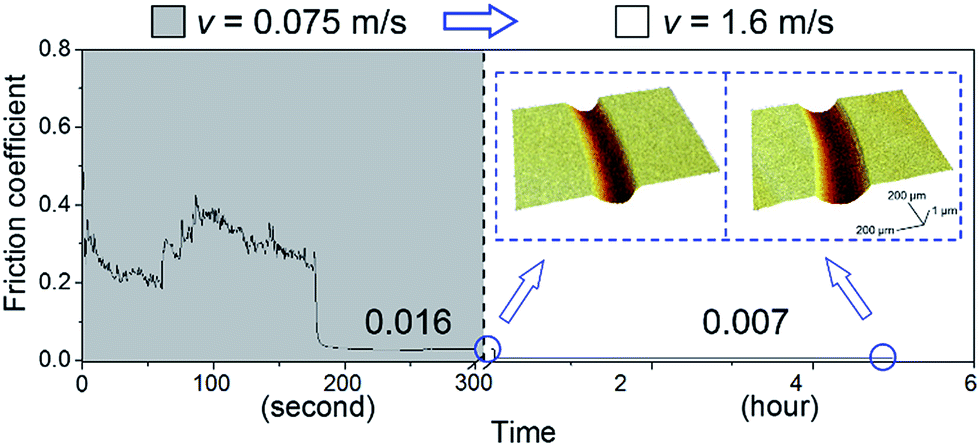 | ||
| Fig. 10 After the running-in process under medium speed (0.075 m s−1), the superlubricity state is sustained for at least 5 hours under the high speed (1.6 m s−1). The insets are the corresponding optical images of glass surfaces after sliding tests. | ||
Conclusions
In present work, the effect of speed on the superlubricity stability of Si3N4/glass pair with H3PO4 solution was investigated, and the failure under low and high speeds was also discussed. Based on these results, the method of realizing stable superlubricity under high speed was proposed. The main conclusions can be summarized as follows:(1) The superlubricity stability of Si3N4/glass pair with H3PO4 solution strongly depends on speed. Stable superlubricity state can be achieved only when the speed is in the range of 0.075 m s−1 to 0.209 m s−1.
(2) The results are consistent with an interpretation that the superlubricity failure under low or high speed may be attributed to the absence of either hydrodynamic effect or hydrated water layer. When the speed is low, the unachievable superlubricity is mainly attributed to the weak hydrodynamic effect, which is not strong enough to separate the tribopair surfaces completely. Under high speed, the special hydrated water layer can hardly form due to the insufficient running-in process, which causes serious surface damage on the glass substrate and further results in the superlubricity failure by restricting the formation of the uniform and effective liquid lubricating layer.
(3) Based on the failure mechanism of superlubricity system with H3PO4 solution, the stable superlubricity state was achieved under high speed after the phosphoric acid–water network formed under the speed less than ∼0.209 m s−1.
Conflicts of interest
There are no conflicts of interest to declare.Acknowledgements
The authors are grateful for the financial support from the National Natural Science Foundation of China (51527901, 51405256), and Self-developed Project of State Key Laboratory of Traction Power (2017TPL_Z02).References
- M. Hirano and K. Shinjo, Phys. Rev. B: Condens. Matter Mater. Phys., 1990, 41, 11837–11851 CrossRef CAS
.
- K. Shinjo and M. Hirano, Surf. Sci., 1993, 283, 473–478 CrossRef CAS
- J. Li and J. Luo, Sci. China: Technol. Sci., 2013, 56, 2877–2887 CrossRef
- A. Erdemir and J.-M. Martin, Superlubricity, Elsevier, New York, 2007 Search PubMed
- J. Xu and J. Li, Friction, 2015, 3, 344–351 CrossRef
- D. Berman, S. A. Deshmukh, S. K. Sankaranarayanan, A. Erdemir and A. V. Sumant, Science, 2015, 348, 1118–1122 CrossRef CAS PubMed
- L. Cui, Z. Lu and L. Wang, Appl. Surf. Sci., 2015, 356, 1082–1085 CrossRef CAS
- A. Erdemir and O. Eryilmaz, Friction, 2014, 2, 140–155 CrossRef CAS
- Z. Gong, X. Jia, W. Ma, B. Zhang and J. Zhang, Appl. Surf. Sci., 2017, 413, 381–386 CrossRef CAS
- P. Manimunda, A. Al-Azizi, S. H. Kim and R. R. Chromik, ACS Appl. Mater. Interfaces, 2017, 9, 16704–16714 CAS
- J. Shi, Z. Gong, Y. Wang, K. Gao and J. Zhang, Appl. Surf. Sci., 2017, 422, 147–154 CrossRef CAS
- P. Liu, Y. Liu, Y. Yang, Z. Chen, J. Li and J. Luo, Langmuir, 2014, 30, 3811–3816 CrossRef CAS PubMed
- J. Li, C. Zhang, M. Deng and J. Luo, RSC Adv., 2015, 5, 30861–30868 RSC
- M. Chen, W. H. Briscoe, S. P. Armes and J. Klein, Science, 2009, 323, 1698–1701 CrossRef CAS PubMed
- J. Klein, E. Kumacheva, D. Mahalu, D. Perahia and L. J. Fetters, Nature, 1994, 370, 634–636 CrossRef CAS
- M. Chen, K. Kato and K. Adachi, Wear, 2001, 250, 246–255 CrossRef
- Y. Shi, I. Minami, M. Grahn, M. Björling and R. Larsson, Tribol. Int., 2014, 69, 39–45 CrossRef CAS
- T. A. Harris, Rolling bearing analysis, John Wiley and sons, New York, 2001 Search PubMed
- J. Li, C. Zhang and J. Luo, Langmuir, 2011, 27, 9413–9417 CrossRef CAS PubMed
- J. Li, L. Ma, S. Zhang, C. Zhang, Y. Liu and J. Luo, J. Appl. Phys., 2013, 114, 114901 CrossRef
- M. Deng, C. Zhang, J. Li, L. Ma and J. Luo, Friction, 2014, 2, 173–181 CrossRef CAS
- M. Deng, J. Li, C. Zhang, J. Ren, N. Zhou and J. Luo, Tribol. Int., 2016, 102, 257–264 CrossRef CAS
- J. Li, C. Zhang, L. Sun, X. Lu and J. Luo, Langmuir, 2012, 28, 15816–15823 CrossRef CAS PubMed
- J. Li, C. Zhang and J. Luo, RSC Adv., 2014, 4, 45735–45741 RSC
- J. Li, C. Zhang, M. Deng and J. Luo, RSC Adv., 2015, 5, 63827–63833 RSC
- B. Bhushan, Principles and applications of tribology, John Wiley & Sons, New York, 2013 Search PubMed
- K. L. Johnson and K. L. Johnson, Contact mechanics, Cambridge university press, Cambridge, 1987 Search PubMed
- J. Li, C. Zhang, L. Sun and J. Luo, Tribol. Trans., 2013, 56, 141–147 CrossRef CAS
- L. Chen, S. H. Kim, X. Wang and L. Qian, Friction, 2013, 1, 81–91 CrossRef CAS
- C. Xiao, C. Chen, J. Guo, P. Zhang, L. Chen and L. Qian, Wear, 2017, 376–377, 188–193 CrossRef CAS
- J. Yu, L. Chen, L. Qian, D. Song and Y. Cai, Appl. Surf. Sci., 2013, 265, 192–200 CrossRef CAS
- J. Yu, H. He, Y. Zhang and H. Hu, Appl. Surf. Sci., 2017, 392, 523–530 CrossRef CAS
- R. C. Dante and C. K. Kajdas, Wear, 2012, 288, 27–38 CrossRef CAS
Footnote |
| † Electronic supplementary information (ESI) available. See DOI: 10.1039/c7ra09217b |
| This journal is © The Royal Society of Chemistry 2017 |