 Open Access Article
Creative Commons Attribution 3.0 Unported Licence
Characterization of thermal and mechanical properties of stanene nanoribbons: a molecular dynamics study
Asir Intisar Khan a,
Ratul Paul
 b and
Samia Subrina
 *a
*a
aDepartment of Electrical and Electronic Engineering, Bangladesh University of Engineering and Technology, Dhaka 1205, Bangladesh. E-mail: samiasubrina@eee.buet.ac.bd; ssubr002@ucr.edu; Fax: +880-02-9668054; Tel: +880-19-3795-9083 Tel: +880-02-9668054
bDepartment of Mechanical Engineering, Bangladesh University of Engineering and Technology, Dhaka 1000, Bangladesh
First published on 30th October 2017
Abstract
Stanene, a buckled honeycomb structure of monolayer tin, has several intriguing electrical and thermoelectrical applications that closely depend on its thermal, mechanical, and electrical properties. However, thermal and mechanical characterizations of stanene nanoribbons (STNRs) have not yet been comprehensively investigated. In this study, we have performed an equilibrium molecular dynamics simulation to characterize the thermal and mechanical properties of STNRs using the modified embedded-atom method potential. The room temperature thermal conductivities of pristine 10 nm × 3 nm zigzag and armchair stanene nanoribbon were estimated to be 0.95 ± 0.024 W m−1 K−1 and 0.89 ± 0.026 W m−1 K−1, respectively. We also studied the thermal conductivity as a function of temperature and width of the ribbon. The thermal conductivity was found to decrease with increasing temperature, whereas it tends to increase with increasing width for both configurations. In all cases, the zigzag STNR exhibited a higher thermal conductivity than its armchair counterpart did. Furthermore, our study includes an investigation of the thermal transport in defected STNRs. For a defect concentration of ∼1.5%, the thermal conductivity of defected stanene nanoribbon experiences a reduction of approximately 30–50%, whereas a ∼70–90% reduction was observed at a vacancy concentration of ∼5% for various types of defects. Finally, the stress–strain behavior of STNRs with varying width was analyzed using uniaxial loading. Zigzag STNRs were found to have higher fracture strength than their armchair counterparts. Moreover, with increasing width, both fracture strain and fracture stress of armchair STNRs were found to show small variations compared with their zigzag counterparts. This study provides insights for tuning the thermo-mechanical characteristics of stanene-based nanostructures for thermal management and possible applications as thermoelectrics.
Introduction
Following the recent technological advancements1 triggered by graphene1–3 because of its combination of electrical properties,4,5 high thermal conductivity6,7 and mechanical strength,8 there has been ongoing increasing interest in the research of two dimensional (2D) nanomaterials. Apart from graphene, researchers have performed experiments with other 2D materials, such as silicene,9 germanene,10 hexagonal boron-nitride (h-BN)11 and molybdenum disulfide (MoS2),12 due to their novel properties13–15 and broad application prospects that range from next generation energy efficient nanoelectronic devices16 to aerospace structures.Recently, a new 2D group IV material, stanene, which is a buckled honeycomb structure of a 2D hexagonal tin film, has incited noteworthy interest due to its intriguing prospect as a quantum Hall insulator,17,18 topological insulator19 and topological superconductor.20 Additionally, the spin orbiting coupling (SOC)19-induced bandgap of ∼0.1 eV for free-standing stanene makes it a promising candidate for nanoelectronic applications.18,21 Moreover, heterobilayers such as stanene/graphene22 and stanene/MoS2 (ref. 23) are reported to show finite band gaps with high carrier mobility which would further promote the development of Sn-based nanoelectronics. In addition, the stable low buckled form of stanene,21,24,25 which was synthesized on a Bi2Te3 (111) substrate by Zhu et al.,26 was theoretically investigated and found to support a large-gap 2D quantum spin Hall (QSH) state at room temperature, thereby enabling superior electric conduction with zero dissipation.18,27 Such 2D QSH systems, such as stanene and stanene with dumbbell units,19,28 can lead to a significant improvement in the thermoelectric figure of merit (zT).29,30 Further improvement in the zT of stanene can be achieved by proper optimization and tuning of the sample size,31 which could enhance the contribution of the gapless edge states, thereby eventually optimizing the electron transport in stanene.
The high thermoelectric performance of a system depends simultaneously on the good electron conductivity and low transport of phonons.32,33 Hence, apart from the electrical properties, the prospect of stanene in thermoelectric applications urges the optimization of the thermal transport characteristics of stanene and its nanostructures. However, there have been markedly fewer investigations of the thermal transport characteristics of stanene and its nanostructures compared with the significant research concentration on its electrical properties. By combining first-principle calculations and the phonon Boltzmann transport equation, Peng et al.34 calculated the lattice thermal conductivity of stanene and obtained a much lower thermal conductivity in stanene lattice in comparison with other 2D materials. The results of Peng et al.34 predict that stanene is a suitable candidate for next-generation thermoelectric devices with its high thermoelectric efficiency. Nissimagoudar et al.35 studied the diffusive nature of the thermal conductivity of a stanene sheet using a phonon Boltzmann transport formalism and density functional theory calculations. For a stanene sheet with a sample size of 1 μm × 1 μm, the calculated lattice thermal conductivities along the zigzag and armchair directions are 10.83 W m−1 K−1 and 9.2 W m−1 K−1 respectively, at room temperature.35 Recently, Cherukara et al.36 proposed a bond order potential for stanene sheet and found the thermal conductivity to be substantially lower than graphene suggesting that stanene can be a promising thermoelectric material. They further expected that, their results would encourage further characterization of stanene, such as the mechanical and thermal properties of stanene ribbons and nanotubes. However, the thermal transport characterization of either pristine or defected stanene nanoribbons (STNRs) has yet to be explored.
On the other hand, the electronic properties of a QSH insulator have been reported to change under deformation and mechanical loading in gallium arsenide (GaAs) films.37 In this context, Mojumder et al.38 investigated the effect of the strain rate and variation of temperature under uniaxial and biaxial loading in both the armchair and zigzag direction of a 20.5 nm × 20.5 nm stanene sheet using molecular dynamics (MD) simulations. However, further investigation is required to study the effect of size on the fracture strain and strength under uniaxial tensile loading of STNRs for proper characterization of the mechanical properties of stanene nanoribbons.
Hence, in this study, we performed molecular dynamics simulation using modified embedded-atom method (MEAM) potential39 parameters to characterize the thermal and mechanical properties of stanene nanoribbons (STNRs). During recent decades, the MEAM potential has been well established for studying material properties,40,41 such as thermal conductivity, thermal resistance40,42 and mechanical stress–strain.38,43 In fact, using MEAM potential parameters, our obtained equilibrium buckling height (0.88 Å) and Sn–Sn bond length (2.83 Å) of stanene match reasonably well with the values obtained experimentally as well as with prior density functional theory (DFT) simulations.44 Using an equilibrium molecular dynamics (EMD) simulation, we computed the thermal conductivity of both armchair and zigzag-configured ∼10 nm × 3 nm STNRs with a variation of temperature in the range of 100 K to 600 K. To study the size dependence of thermal conductivity in STNRs, we also computed the room temperature thermal conductivity of STNRs with varying widths in the range of ∼2 nm to 6 nm while the length was kept fixed at 10 nm. Next, considering the inevitable presence of some form of structural defects during the synthesis, integration and processing of nanoribbons, we studied the impact of three types of vacancies, point vacancy, edge vacancy and bi-vacancy, on the thermal conductivity of STNRs. Finally, we report the stress–strain behavior of both armchair- and zigzag-configured STNRs with increasing widths under uniaxial tensile loading.
Methods
In this study, we conducted molecular dynamics simulation using Large-scale Atomic/Molecular Massively Parallel Simulator (LAMMPS)45 to investigate the thermal and mechanical properties of stanene nanoribbons. The Modified Embedded-Atom Method (MEAM) potential parameters for stanene38,39 were employed to perform the MD simulations.To compute the thermal conductivity of both armchair and zigzag STNRs, an EMD simulation based on the linear response theorem was used in this study. In this method, the thermal conductivity computation is related to the ensemble average of the heat current auto correlation function (HCACF) by following the Green–Kubo formulation:
 | (1) |
 | (2) |
A periodic boundary condition along the zigzag and armchair direction was applied. A fixed time step of 0.5 fs was used throughout all of the simulations. The velocity-Verlet integrator46 was used to integrate Newton's classical equations of motion. The structures were equilibrated using a Nose–Hoover thermostat for 3 × 10⁵ time steps followed by constant volume, constant energy ensemble (NVE) for 105 time steps, whereas the energy minimization was performed using the steepest descent algorithm. In-plane heat current data were recorded every 5 steps by performing constant energy simulations, and heat flux autocorrelation values were calculated by averaging 10 obtained HCACFs. Then, a 10 ps correlation time was used for all simulations to allow the HCACFs to decay to zero. Finally, using eqn (1), a converged value of the average thermal conductivity was calculated using the computed thermal conductivity values from 5 independent microcanonical ensembles (constant number of particles, volume and energy), i.e., NVE ensembles, each starting with a different initial velocity of the molecules.
For the calculation of the phonon density of states (PDOS), the FixPhonon command47 of LAMMPS was employed to directly obtain the dynamical matrices from the MD simulation based on fluctuation–dissipation theory. Using dynamical matrices, an auxiliary post-processing code, ‘phana’, was then used for the evaluation of the PDOS of the STNRs. In this study, alongside the uniform generation of q (wave vector) points, we used a tricubic48 interpolation method to compute the phonon density of states for both pristine and defected STNRs.
For the specific characterization of the mechanical properties to observe the strain–stress behavior of the stanene nanoribbon, we performed MD simulations in LAMMPS using MEAM potential parameters.38,39 Equations of motions were integrated with a time step of 1 fs. The steepest descent algorithm was used to relax the initial geometry. The initial structure was equilibrated using a constant pressure and constant temperature (NPT) ensemble for 30 ps followed by an NVE ensemble for 10 ps to stabilize the system temperature and pressure. Then, a uniaxial tensile loading was applied along the zigzag or armchair direction at a constant strain rate of 108 s−1 and at a temperature of 100 K. Stresses in LAMMPS were calculated using the following formula:38,49
 | (3) |
![[u with combining dot above]](https://www.rsc.org/images/entities/i_char_0075_0307.gif) i is the velocity of the atoms, rij is the position vector of atom, ⊗ is the cross product, and fij is the interatomic force applied on atom i by atom j. The thickness of the stanene nanoribbon was taken to be 4.5 Å. To minimize the stress fluctuations caused by thermal fluctuations, the atomic stresses were averaged over a time interval of every 100 time steps.
i is the velocity of the atoms, rij is the position vector of atom, ⊗ is the cross product, and fij is the interatomic force applied on atom i by atom j. The thickness of the stanene nanoribbon was taken to be 4.5 Å. To minimize the stress fluctuations caused by thermal fluctuations, the atomic stresses were averaged over a time interval of every 100 time steps.
The electronic properties of the proposed heterobilayer structure are investigated using the density-functional theory (DFT) with a plane-wave basis set using the Ab initio code PWSCF package of Quantum Espresso.50 The electron–ion interactions are accounted using Troullier Martin pseudo-potentials. To describe the electron exchange correlation energy, the generalized gradient approximation (GGA) with Perdew–Burke–Ernzerhof (PBE) exchange correlation functional is implemented. For the structural optimization, the plane wave basis cut off is set at 550 eV (40 Ry) with a convergence threshold on force of 10−4 Ry a.u−1. The first Brillouine zone of the unit cell is sampled with a 12 × 12 × 1 Monkhorst–Pack grid for the geometry optimization and a 15 × 15 × 1 grid for the subsequent calculations.
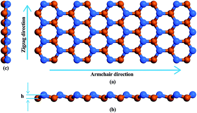
Fig. 1 is a schematic representation of the atomic structure of a low buckled phase stanene nanoribbon with a Sn–Sn bond length of 2.83 Å. Structural optimization i.e., energy minimization, was performed using the steepest descent algorithm. The buckling height of the relaxed structure is 0.88 Å. This hexagonal structure with low buckling is geometrically similar to silicene, germanene and blue phosphorene10,51–53 but different from the planar geometric configuration of graphene nanoribbons (GNRs) and hexagonal boron nitride nanoribbons (h-BNNRs).54,55
We considered 10 nm × 3 nm armchair stanene nanoribbon structures with 3 types of vacancies as represented in Fig. 2. The structure with point vacancy results from the random removal of a single atom from the lattice is depicted in Fig. 2(a). As shown in Fig. 2(b), edge vacancy can be considered as a special form of point vacancy and involves removing atoms solely from the lattice boundary. Fig. 2(c) presents the stanene nanoribbon structure with bi-vacancy, which originates from either the lumping of two consecutive point vacancies or from the random elimination of a pair of bonding atoms.
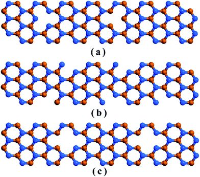 | ||
| Fig. 2 Schematic representation of an armchair stanene nanoribbon including (a) point vacancy, (b) edge vacancy, and (c) bi-vacancy. Atoms in different planes are represented with different colors. | ||
Results and discussions
Our computed average thermal conductivity for a 10 nm × 3 nm zigzag stanene nanoribbon using MEAM potential parameters at room temperature (300 K) is 0.95 ± 0.024 W m−1 K−1, whereas the estimated value of the average thermal conductivity is 0.89 ± 0.026 W m−1 K−1 for armchair stanene nanoribbon as shown in Fig. 3. Cherukura et al.36 reported a room temperature thermal conductivity value of ∼3 W m−1 K−1 for both zigzag and armchair configured 80 nm × 80 nm stanene sheets, and they expected these values to decrease even further with nanostructuring, which is in accordance with our reported result for a stanene nanoribbon in both configurations.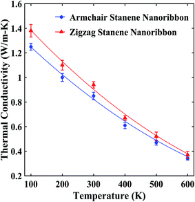 | ||
| Fig. 3 Temperature dependence of the average thermal conductivity of ∼10 nm × 3 nm stanene nanoribbon. The solid lines represent numerically fitted curves through the data. | ||
Additionally, using the phonon Boltzmann transport formalism and density functional theory calculations, Nissimagoudar et al.35 reported a thermal conductivity value of 1.6 W m−1 K−1 for a 100 nm × 100 nm stanene sheet. The authors35 also mentioned the possibility of a further reduction in the thermal conductivity of stanene with a reduction in the dimensionality of the sample, i.e., nanoribbons, which is in line with the computed value of the thermal conductivity in our study. The calculated values of thermal conductivity for the stanene nanoribbon in this study are significantly smaller compared with other 2D hexagonal materials and nanostructures such as GNRs (∼3000 W m−1 K−1)56,57 and h-BNNRs (∼400–600 W m−1 K−1).55,58
This can first be attributed to the lower Debye temperature of ∼72 K for stanene34,35 compared with graphene (∼1160 K (ref. 35)), GNRs (322 K (ref. 54)), h-BNNRs (410 K (ref. 55)), and monolayer molybdenum disulfide (MoS2) (500 K (ref. 59)). This significantly low Debye temperature for stanene originated from the high atomic mass of tin (118.71) and weaker bonding between tin atoms.35 Second, much smaller phonon group velocities for longitudinal acoustic (LA), transverse acoustic (TA) and out of plane (ZA) branches of stanene have been reported34,35 in contrast to those of graphene, hexagonal boron nitride (h-BN), silicene, germanene, MoS2 and blue phosphorenes.34,60–62 These lower phonon group velocities caused by the low Debye temperature of stanene, which are accompanied by higher phonon scattering rates,34 lower the thermal conductivity of STNRs.
Fig. 3 shows that with an increase of temperature from 100 K to 600 K, the thermal conductivities of the STNRs decays for both armchair and zigzag configurations at slightly different rates. This decaying trend above the Debye temperature (∼72 K for stanene) is similar to the study of Peng et al.34 for a stanene lattice structure, which used the single mode relaxation approximation method and to a molecular dynamics study by Cherukara et al.,36 which used an optimized Tersoff potential for 80 nm × 80 nm stanene sheets. This is also in agreement with the reported trend for other 2D hexagonal materials, such as graphene nanoribbon,54,56 BNNRs55,58 and monolayer MoS2.63
Moreover, as shown in Fig. 3, at lower temperatures, zigzag nanoribbons exhibit a higher thermal conductivity than the armchair configurations, which is in agreement with the study of stanene nanotubes36 as well as other 2D nanostructures, such as GNRs,64 carbon nanotubes,65 and h-BNNRs.58 However, at an elevated temperature, the armchair and zigzag configurations exhibit a very small anharmonicity, i.e., a small difference in thermal conductivity values. This is due to the comparatively higher group velocities of the armchair-configured stanene nanoribbon compared with the zigzag configuration at higher temperature.35
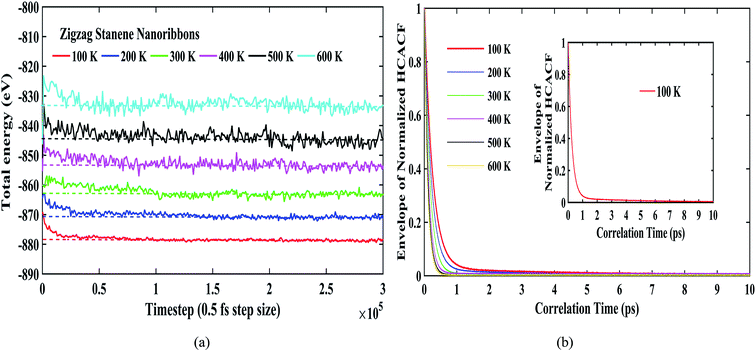
Fig. 4(a) shows the total energies during the simulation for our considered temperature range. As shown in the figure, the energy fluctuations were negligible, thereby reflecting the stability of the stanene nanoribbon structure. The dotted lines for each temperature further depict the convergence of the total energies for different temperatures. Fig. 4(b) depicts the reasonable decay of the heat current autocorrelation function required for the computation of the thermal conductivity using the Green–Kubo method. Furthermore, Fig. 4(b) can be taken into consideration to explain the decrease in thermal conductivity with the increasing temperature for the STNRs. With increasing temperature, phonon–phonon scattering, specifically Umklapp scattering, increases due to the increasing number of phonons.34–36 As a result, with the increase in temperature, the HCACF profile decays to zero within a quicker time,66 which results in the computation of a decreasing thermal conductivity for STNRs.
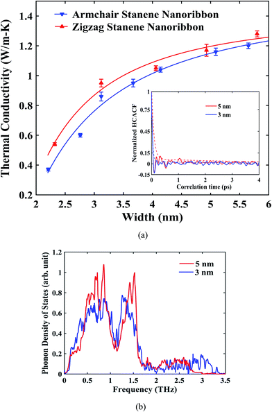
The influence of width of the sample on the thermal conductivity of zigzag and armchair STNRs is shown in Fig. 5. A reasonable decay for HCACF was maintained, which ensured the good convergence of the Green–Kubo integral as shown in the inset of Fig. 5(a). As depicted in Fig. 5(a), for both STNR configurations, the room temperature thermal conductivity increased with an increase in width ranging from ∼2 nm to ∼6 nm. This increasing trend for the thermal conductivity with width is in agreement with the study by Peng et al.34 for stanene nanowires. Furthermore, our study shows that thermal conductivity increases rapidly initially with increasing width, and further increases in width results in smaller increments of thermal conductivity. Two- dimensional hexagonal GNRs and h-BNNRs have been reported to show a similar variation in the literature.54,57,58
The width dependence of thermal conductivity is influenced by both the edge localized phonon boundary scattering effect and anharmonic phonon–phonon scattering effects. Each of these has negative effects on the thermal conductivity value of stanene. For the smaller sample sizes considered in this study, phonon boundary scattering mostly dominates the thermal conductivity of STNRs.35 In this case, with an increasing width, the edge-localized phonon scattering effect becomes suppressed, resulting in an increased thermal conductivity.35,57,67 In fact, for a 2D stanene sheet, using phonon Boltzmann transport formalism, Nissimagoudar et al.35 have reported that, the influence of phonon boundary scattering increases with the decrease in width, which reduces the thermal conductivity. This is in good agreement with our study on the width dependence of thermal conductivity in stanene nanoribbons.
To provide further insight into the width dependence of the thermal conductivity of STNRs, Fig. 5(b) can be taken into consideration. The phonon density of states for varying widths of STNRs is shown in Fig. 5(b) with a fixed length of 10 nm. As shown in the figure, the magnitude of the dominant peaks is higher in case of 5 nm width. In fact, more low frequency i.e. long wavelength acoustic phonons are available with the increasing width for STNRs. Recently, Peng et al.34 showed that because of higher group velocities and a lower scattering rate, low frequency phonons provide the major contribution to the thermal conductivity of stanene. As a result, with the increase in width, thermal conductivity increases.
Furthermore, the phonon density of states (PDOS) of stanene is limited in the low frequency region of the phonon spectrum, whereas the range of PDOS for graphene is up to 50 to 60 THz.66 In fact, the presence of high-frequency peaks (∼50 THz) in the phonon power spectrum of graphene as opposed to the low-frequency peaks in stanene provides further insight into the significantly smaller thermal conductivity of STNRs compared with to GNRs.68
The experimental synthesis, integration and fabrication process of stanene is inevitably associated with some forms of structural defects and vacancies. Such defects have a significant impact on the chemical, physical and thermal properties of materials.69 Thus, from a practical perspective, a study on how these defects influence the thermal conductivity of STNRs is essential for its proper thermal transport characterization. Moreover, it would enhance the possibility of further tuning the thermal conductivity of STNRs for a better thermoelectric performance. Hence, from this point of view, by varying the defect concentrations, we next performed EMD simulations using the MEAM potential to investigate the thermal conductivity of armchair STNRs with different types of vacancies, namely, point vacancy, edge vacancy and bi-vacancy. In this study, defect or vacancy concentrations are defined as the percentage ratio of the number of random vacancies to the total number of tin atoms considered.
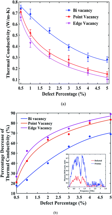
Fig. 6(a) suggests that, for all types of vacancies, the thermal conductivity of stanene nanoribbon decreases monotonically with an increase in the defect percentage. As observed from the figure, edge vacancy and point vacancies impose a significant reduction in thermal conductivity, whereas bi-vacancy was found to be less severe in terms of reduction in thermal conductivity. For GNRs and h-BNNRs, a similar exponential decay of the thermal conductivity in the presence of various types of defects has been reported in the literature.66,70–72 Again, for all three types of vacancies, the thermal conductivity profile shows a fast decrease at low defect concentrations (0.5% to 3%); then, the decay rate ceases for higher defect concentrations up to 5%.
The percentage reduction in thermal conductivity of STNRs with different types of vacancies compared with the same-sized pristine stanene nanoribbon is presented in Fig. 6(b). For a defect concentration of ∼1.5%, the thermal conductivity of defected stanene nanoribbon experiences a reduction of approximately 30–50%, whereas a ∼70–90% reduction was observed at a vacancy concentration of ∼5% for various types of defects.
The PDOS shown in the inset of Fig. 6(b) can be taken into consideration for the reduction of the thermal conductivity in the presence of a vacancy in STNRs. The peaks in the phonon spectrum in the low frequency region are damped out in the case of STNRs with vacancy, which is in accordance with the reported literature for defected graphene and GNRs with vacancies.66,70–72 These low frequency phonons are found to be the main contributor to the thermal conductivity of stanene.34 Hence, the softening of phonon peaks in the low frequency region for the defected structure as opposed to the pristine stanene nanoribbon can be attributed to the observed percentage decrease in thermal conductivity in Fig. 6(b). Furthermore, significant phonon scattering at and around vacancy centers causes a reduction in the phonon mean free path,66,73 thereby reducing the thermal conductivity of STNRs with several types of vacancies. A similar phenomenon is expected to be observed in the zigzag configuration with vacancies.
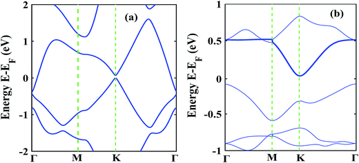
The low thermal conductivity of pristine STNRs and further lower thermal conductivity of the defected STNRs with several types of vacancies enhance the applicability of STNRs as thermoelectrics. However, the high thermoelectric performance of a system depends simultaneously on the low transport of phonons and the good electron conductivity. Hence, using DFT, we have computed the electronic band structures of pristine stanene and stanene with a point vacancy as shown in Fig. 7(a) and (b), respectively. As can be seen from Fig. 7, in the presence of spin orbital coupling, a finite band gap is opened in the band structures for both the pristine and defected stanene structures while the linear Dirac dispersion relation is nearly preserved at the K point. Using the conduction band in the obtained band structure, the electron effective mass can be calculated from the following formula:
 | (4) |
The calculated electron effective mass for pristine and defected stanene are ∼0.49 × 10⁶ ms−1 and ∼0.2 × 10⁶ ms−1 respectively. Here, mo is the mass of an electron. The small electron effective mass and the high Fermi velocity indicate the high carrier mobility in our studied structure, thereby ensuring its applicability as thermoelectrics. Our computed electron transport characteristics of pristine as well as defected stanene are in good agreement with the reported literature.21,74
In this section, using a molecular dynamics simulation with MEAM potential parameters, we present a comprehensive study of the size and chirality effects on the mechanical properties of STNRs under uniaxial tensile strain. Nominal strain and virial stress were used in this study to analyze the strain stress behavior.
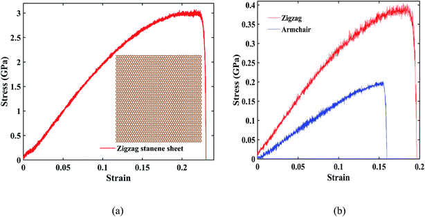
Fig. 8(a) represents the stress–strain curve under uniaxial tensile loading in the zigzag direction for a 20 nm × 20 nm stanene sheet (shown at inset) at 100 K with a strain rate of 108 s−1. As shown in the figure, a maximum stress of ∼3 GPa was found at a fracture strain of ∼24%, which is in good agreement with the study by Mojumder et al.38 Stress–strain curves of ∼10 nm × 6 nm STNRs under zigzag and armchair uniaxial tensile loading are shown in Fig. 8(b). The zigzag stanene nanoribbon has a higher stress as well as a higher fracture strain compared with the armchair stanene nanoribbon with a sudden drop in the stress profile after a certain stress for both configurations. This trend is in agreement with the study of a stanene sheet by Mojumder et al.38 as well as studies on GNRs.75,76
For ∼10 nm × 6 nm STNRs, our computed value for the fracture strain along the armchair direction is ∼16%, whereas along the zigzag direction, it is ∼20%. The breaking stresses for armchair and zigzag stanene nanoribbons are ∼0.2 GPa and ∼0.4 GPa, respectively. The higher strength in the zigzag direction compared with the armchair direction can be attributed to the difference in bond orientation along the direction of loading.38
The fracture pattern for uniaxial zigzag loading for stanene nanoribbon at a strain rate of 108 s−1 and at 100 K is shown in Fig. 9. As the figure shows, with an increase in strain, a crack is initiated and propagated with the breaking of Sn–Sn atomic bonds, and there is a subsequent decrease in the cross-sectional area, leading to the ultimate fracture of the stanene nanoribbon. Similar fracture behavior has been observed in other 2D materials, such as silicene and GNRs.75
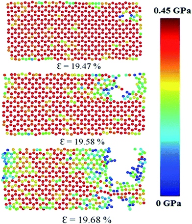 | ||
| Fig. 9 Fracture pattern of a ∼10 nm × 6 nm zigzag stanene nanoribbon under uniaxial tension at a strain rate of 108 s−1 and at 100 K. The atomic stress in GPa is shown in the color bar. | ||
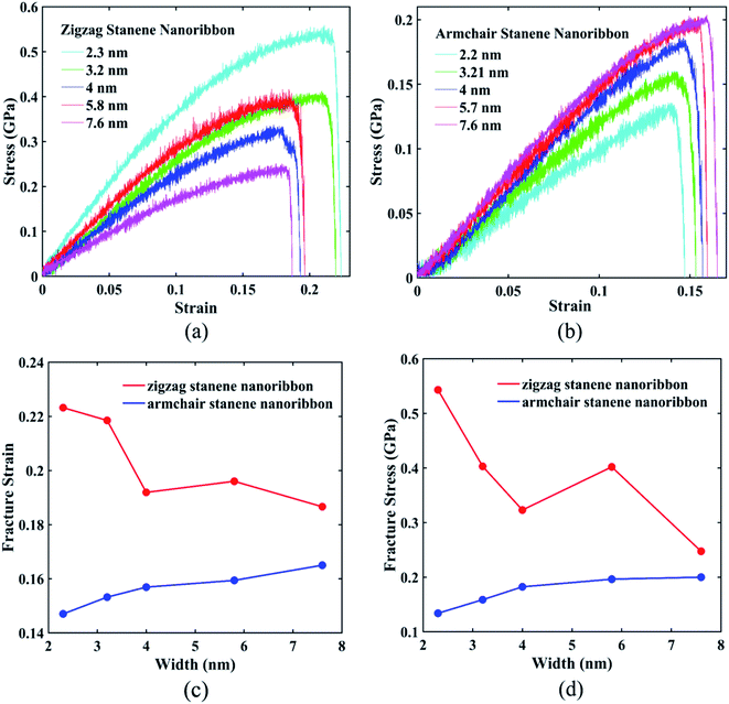
Fig. 10(a) and (b) interprets the strain–stress dependence of STNRs for various widths with zigzag and armchair edges, respectively. Fig. 10(c) shows the variation of fracture strain of both armchair and zigzag STNRs with increasing width, whereas Fig. 10(d) represents the failure stress for stanene nanoribbons of varying width in both armchair and zigzag directions. As the figures show, both the fracture strain and fracture stress of zigzag stanene nanoribbon are always higher compared with those of armchair stanene nanoribbons. Moreover, the fracture strain and maximum stress or fracture stress of armchair stanene nanoribbons have small variations with an increasing width compared with their zigzag counterparts. For similarly sized GNRs, this trend is in agreement with the study by Chu et al.75 This phenomenon can be attributed to the difference in failure mechanism for the armchair and zigzag directions. Nucleation of fracture starts from the edge for the armchair direction, whereas for the zigzag direction, it begins from the interior region.75 Therefore, the initial bond breaking of Sn–Sn in the zigzag direction depends on the width. As a result, the variation in the fracture stress and the fracture strain with increasing width is higher for zigzag STNRs compared with their armchair counterparts.
Conclusion
In summary, we studied the thermo-mechanical properties of stanene nanoribbons using MD simulations with MEAM potential parameters. In this study, we investigated the thermal conductivity of both zigzag and armchair STNRs using EMD simulations based on the Greek–Kubo method. At room temperature, our computed thermal conductivity for 10 nm × 3 nm STNRs in the zigzag and armchair directions are 0.95 W m−1 K−1 and 0.89 W m−1 K−1, respectively. The computed values of thermal conductivity are significantly smaller in STNRs due to lower Debye temperature of stanene accompanied by lower phonon group velocities and a higher scattering rate compared with other similarly sized 2D hexagonal nanoribbons, such as GNRs and h-BNNRs. Our study shows that the thermal conductivity of STNRs follows an inverse relation with temperature for both armchair and zigzag configurations. We also studied the width dependence of the thermal conductivity, and the thermal conductivity was found to increase with increasing width for both configurations, which is in agreement with our computed PDOS for STNRs. In all cases, the zigzag STNR exhibited a higher thermal conductivity than its armchair counterpart did. Significant phonon scattering at and around vacancy centers causes a reduction of the thermal conductivity with vacancies, thereby enhancing the applicability of stanene nanoribbons in thermoelectrics. Edge vacancy and point vacancies were found to be more destructive than bi-vacancy in terms of reduction in thermal conductivity. Finally, the effects of size and chirality on the mechanical properties of STNRs under a uniaxial tensile strain at 100 K and at a strain rate of 108 s−1 were studied using MD simulations. The stress–strain behavior of zigzag- and armchair-configured STNRs showed that zigzag STNRs have a comparatively higher strength and higher fracture strain compared with that of armchair STNRs. Furthermore, with increasing width, both fracture strain and fracture stress of armchair STNRs were found to show small variations compared with their zigzag counterparts. Overall, apart from providing an insight into the thermo-mechanical characteristics of stanene nanoribbons, this study investigated how to tune these characteristics for efficient practical design of thermoelectrics. Thus, our study will aid in the design of thermoelectrics as well as nanoelectronic devices based on stanene nanoribbons and encourages further investigation on the proper optimization of thermo-mechanical characteristics of stanene nanostructures.Author contributions
A. I. K. conceived the work; A. I. K. and R. P. performed the simulations under the supervision of S. S. All authors discussed and analyzed the data and interpretation and contributed during the writing of the manuscript.Conflicts of interest
There are no conflicts of interest to declare.References
- A. K. Geim and K. S. Novoselov, Nat. Mater., 2007, 6, 183–191 CrossRef CAS PubMed.
- K. S. Novoselov, A. K. Geim, S. V. Morozov, D. Jiang, Y. Zhang, S. V. Dubonos, I. V. Grigorieva and A. A. Firsov, Science, 2004, 306, 666–669 CrossRef CAS PubMed.
- K. S. Novoselov, D. Jiang, F. Schedin, T. J. Booth, V. V. Khotkevich, S. V. Morozov and A. K. Geim, Proc. Natl. Acad. Sci. U. S. A., 2005, 102, 10451–10453 CrossRef CAS PubMed.
- J. R. Williams, L. Dicarlo and C. M. Marcus, Science, 2007, 317, 638–641 CrossRef CAS PubMed.
- K. S. Novoselov, A. K. Geim, S. V. Morozov, D. Jiang, M. I. Katsnelson, I. V. Grigorieva, S. V. Dubonos and A. A. Firsov, Nature, 2005, 438, 197–200 CrossRef CAS PubMed.
- K. Nakada, M. Fujita, G. Dresselhaus and M. S. Dresselhaus, Phys. Rev. B: Condens. Matter Mater. Phys., 1996, 54, 17954–17961 CrossRef CAS.
- Y. W. Son, M. L. Cohen and S. G. Louie, Phys. Rev. Lett., 2006, 97, 1–4 Search PubMed.
- C. Lee, X. Wei, J. W. Kysar and J. Hone, Science, 2008, 321, 385–388 CrossRef CAS PubMed.
- N. D. Drummond, V. Zólyomi and V. I. Fal'Ko, Phys. Rev. B: Condens. Matter Mater. Phys., 2012, 85, 1–7 CrossRef.
- C. C. Liu, W. Feng and Y. Yao, Phys. Rev. Lett., 2011, 107, 1–4 Search PubMed.
- K. Watanabe, T. Taniguchi and H. Kanda, Nat. Mater., 2004, 3, 404–409 CrossRef CAS PubMed.
- B. Radisavljevic, A. Radenovic, J. Brivio, V. Giacometti and A. Kis, Nat. Nanotechnol., 2011, 6, 147–150 CrossRef CAS PubMed.
- A. A. Balandin, S. Ghosh, W. Bao, I. Calizo, D. Teweldebrhan, F. Miao and C. N. Lau, Nano Lett., 2008, 8, 902–907 CrossRef CAS PubMed.
- S. Balendhran, S. Walia, H. Nili, S. Sriram and M. Bhaskaran, Small, 2015, 11, 640–652 CrossRef CAS PubMed.
- R. Mas-Ballesté, C. Gómez-Navarro, J. Gómez-Herrero and F. Zamora, Nanoscale, 2011, 3, 20–30 RSC.
- K. S. Novoselov, V. I. F. ko, L. Colombo, P. R. Gellert, M. G. Schwab and K. Kim, Nature, 2013, 490, 192–200 CrossRef PubMed.
- M. Ezawa, J. Supercond. Novel Magn., 2015, 28, 1249–1253 CrossRef CAS.
- Y. Xu, B. Yan, H. J. Zhang, J. Wang, G. Xu, P. Tang, W. Duan and S. C. Zhang, Phys. Rev. Lett., 2013, 111, 1–5 Search PubMed.
- S. Rachel and M. Ezawa, Phys. Rev. B: Condens. Matter Mater. Phys., 2014, 89, 1–6 CrossRef.
- S. Li, C. De La Cruz, Q. Huang, Y. Chen, J. W. Lynn, J. Hu, Y. L. Huang, F. C. Hsu, K. W. Yeh, M. K. Wu and P. Dai, Phys. Rev. B: Condens. Matter Mater. Phys., 2009, 79, 1–7 Search PubMed.
- B. van den Broek, M. Houssa, E. Scalise, G. Pourtois, V. V. Afanas'ev and A. Stesmans, 2D Mater., 2014, 1, 21004 CrossRef.
- X. Chen, R. Meng, J. Jiang, Q. Liang, Q. Yang, C. Tan, X. Sun, S. Zhang and T. Ren, Phys. Chem. Chem. Phys., 2016, 18, 16302–16309 RSC.
- C.-C. Ren, Y. Feng, S.-F. Zhang, C.-W. Zhang and P.-J. Wang, RSC Adv., 2017, 7, 9176–9181 RSC.
- A. Manjanath, V. Kumar and A. K. Singh, Phys. Chem. Chem. Phys., 2014, 16, 1667–1671 RSC.
- W. Xiong, C. Xia, T. Wang, J. Du, Y. Peng, X. Zhao and Y. Jia, Phys. Chem. Chem. Phys., 2016, 18, 28759–28766 RSC.
- F.-F. Zhu, W.-J. Chen, Y. Xu, C.-L. Gao, D.-D. Guan, C.-H. Liu, D. Qian, S.-C. Zhang and J.-F. Jia, Nat. Mater., 2015, 14, 1020–1025 CrossRef CAS PubMed.
- D. Wang, L. Chen, X. Wang, G. Cui and P. Zhang, Phys. Chem. Chem. Phys., 2015, 17, 26979–26987 RSC.
- Y. P. Wang, W. X. Ji, C. W. Zhang, P. Li, F. Li, P. J. Wang, S. S. Li and S. S. Yan, Appl. Phys. Lett., 2016, 108, 1–6 Search PubMed.
- R. Takahashi and S. Murakami, Phys. Rev. B: Condens. Matter Mater. Phys., 2010, 81, 1–4 Search PubMed.
- S. Murakami, R. Takahashi, O. A. Tretiakov, A. Abanov and J. Sinova, J. Phys.: Conf. Ser., 2011, 334, 12013 CrossRef.
- Y. Xu, Z. Gan and S. C. Zhang, Phys. Rev. Lett., 2014, 112, 1–5 Search PubMed.
- L.-D. Zhao, S.-H. Lo, Y. Zhang, H. Sun, G. Tan, C. Uher, C. Wolverton, V. P. Dravid and M. G. Kanatzidis, Nature, 2014, 508, 373–377 CrossRef CAS PubMed.
- L.-D. Zhao, G. Tan, S. Hao, J. He, Y. Pei, H. Chi, H. Wang, S. Gong, H. Xu, V. P. Dravid, C. Uher, G. J. Snyder, C. Wolverton and M. G. Kanatzidis, Science, 2016, 351, 141–144 CrossRef CAS PubMed.
- B. Peng, H. Zhang, H. Shao, Y. Xu, X. Zhang and H. Zhu, Sci. Rep., 2016, 6, 20225 CrossRef CAS PubMed.
- A. S. Nissimagoudar, A. Manjanath and A. K. Singh, Phys. Chem. Chem. Phys., 2016, 18, 14257–14263 RSC.
- M. J. Cherukara, B. Narayanan, A. Kinaci, K. Sasikumar, S. K. Gray, M. K. Y. Chan and S. K. R. S. Sankaranarayanan, J. Phys. Chem. Lett., 2016, 7, 3752–3759 CrossRef CAS PubMed.
- M. Zhao, X. Zhang and L. Li, Sci. Rep., 2015, 5, 16108 CrossRef PubMed.
- S. Mojumder, A. Al Amin and M. M. Islam, J. Appl. Phys., 2015, 118, 124305 CrossRef.
- M. I. Baskes, Phys. Rev. B: Condens. Matter Mater. Phys., 1992, 46, 2727–2742 CrossRef CAS.
- C. Abs, P. Chantrenne, R. Gomes, D. A. Veiga, M. Perez and X. Kleber, J. Appl. Phys., 2013, 23710, 1–9 Search PubMed.
- B.-J. Lee, J.-H. Shim and M. I. Baskes, Phys. Rev. B: Condens. Matter Mater. Phys., 2003, 68, 144112 CrossRef.
- K. Termentzidis, J. Parasuraman, C. Abs, D. Cruz, S. Merabia, D. Angelescu, F. Marty, T. Bourouina, X. Kleber, P. Chantrenne and P. Basset, Nanoscale Res. Lett., 2011, 6, 1–10 CrossRef PubMed.
- Q.-X. Pei, Z.-D. Sha, Y.-Y. Zhang and Y.-W. Zhang, J. Appl. Phys., 2014, 115, 23519 CrossRef.
- S. Saxena, R. P. Choudhary and S. Shukla, Sci. Rep., 2015, 6, 1–4 Search PubMed.
- S. Plimpton, J. Comput. Phys., 1995, 117, 1–19 CrossRef CAS.
- D. L. Cheung, L. Anton, M. P. Allen and A. J. Masters, Comput. Phys. Commun., 2008, 179, 61–65 CrossRef CAS.
- L. T. Kong, Comput. Phys. Commun., 2011, 182, 2201–2207 CrossRef CAS.
- F. Lekien and J. Marsden, Int. J. Numer. Meth. Eng., 2005, 63, 455–471 CrossRef.
- M. M. Islam, A. Ostadhossein, O. Borodin, A. T. Yeates, W. W. Tipton, R. G. Hennig, N. Kumar and A. C. T. van Duin, Phys. Chem. Chem. Phys., 2015, 17, 3383–3393 RSC.
- P. Giannozzi, S. Baroni, N. Bonini, M. Calandra, R. Car, C. Cavazzoni, D. Ceresoli, G. L. Chiarotti, M. Cococcioni, I. Dabo, A. D. Corso, S. Fabris, G. Fratesi, S. de Gironcoli, R. Gebauer, U. Gerstmann, C. Gougoussis, A. Kokalj, M. Lazzeri, L. Martin-Samos, N. Marzari, F. Mauri, R. Mazzarello, S. Paolini, A. Pasquarello, L. Paulatto, C. Sbraccia, S. Scandolo, G. Sclauzero, A. P. Seitsonen, A. Smogunov, P. Umari and R. M. Wentzcovitch, J. Phys.: Condens. Matter, 2009, 21, 395502 CrossRef PubMed.
- F. Matusalem, M. Marques, L. K. Teles and F. Bechstedt, Phys. Rev. B: Condens. Matter Mater. Phys., 2015, 92, 1–8 CrossRef.
- C. C. Liu, H. Jiang and Y. Yao, Phys. Rev. B: Condens. Matter Mater. Phys., 2011, 84, 1–11 CAS.
- A. Jain and A. J. H. McGaughey, Sci. Rep., 2015, 5, 8501 CrossRef CAS PubMed.
- A. I. Khan, I. A. Navid, M. Noshin, H. M. A. Uddin, F. F. Hossain and S. Subrina, Electronics, 2015, 4, 1109–1124 CrossRef.
- S. J. Mahdizadeh, E. K. Goharshadi and G. Akhlamadi, J. Mol. Graphics Modell., 2016, 68, 1–13 CrossRef CAS PubMed.
- S. J. Mahdizadeh and E. K. Goharshadi, J. Nanopart. Res., 2014, 16, 1–12 CrossRef CAS.
- W. J. Evans, L. Hu and P. Keblinski, Appl. Phys. Lett., 2010, 96, 1–3 CrossRef.
- C. Sevik, A. Kinaci, J. B. Haskins and T. Cagin, Phys. Rev. B: Condens. Matter Mater. Phys., 2011, 84, 1–7 CrossRef.
- A. Pisoni, J. Jacimovic, O. S. Barišić, A. Walter, B. Náfrádi, P. Bugnon, A. Magrez, H. Berger, Z. Revay and L. Forró, J. Phys. Chem. C, 2015, 119, 3918–3922 CAS.
- A. Alofi and G. Srivastava, Phys. Rev. B: Condens. Matter Mater. Phys., 2013, 87, 115421 CrossRef.
- M. Hu, X. Zhang and D. Poulikakos, Phys. Rev. B: Condens. Matter Mater. Phys., 2013, 87, 1–11 Search PubMed.
- Z. Y. Ong and E. Pop, Phys. Rev. B: Condens. Matter Mater. Phys., 2011, 84, 1–7 Search PubMed.
- W. Li, J. Carrete and N. Mingo, Appl. Phys. Lett., 2013, 103, 32–36 Search PubMed.
- Z. Guo, D. Zhang and X.-G. Gong, Appl. Phys. Lett., 2009, 95, 163103 CrossRef.
- Z. Han and A. Fina, Prog. Polym. Sci., 2011, 36, 914–944 CrossRef CAS.
- M. Noshin, A. I. Khan, I. A. Navid, H. M. A. Uddin and S. Subrina, AIP Adv., 2017, 7, 15112 CrossRef.
- H. Cao, Z. Guo, H. Xiang and X. Gong, Phys. Lett. A, 2011, 376, 525–528 CrossRef.
- A. I. Khan, R. Paul and S. Subrina, RSC Adv., 2017, 7, 44780–44787 RSC.
- D. Liu, P. Yang, X. Yuan, J. Guo and N. Liao, Phys. Lett. A, 2015, 379, 810–814 CrossRef CAS.
- B. Mortazavi and S. Ahzi, Carbon, 2013, 63, 460–470 CrossRef CAS.
- J. J. Yeo, Z. Liu and T. Y. Ng, Nanotechnology, 2012, 23, 385702 CrossRef PubMed.
- H. Zhang, G. Lee and K. Cho, Phys. Rev. B: Condens. Matter Mater. Phys., 2011, 84, 1–5 Search PubMed.
- F. Hao, D. Fang and Z. Xu, Appl. Phys. Lett., 2011, 99, 2011–2014 Search PubMed.
- L. Shen, M. Lan, X. Zhang and G. Xiang, RSC Adv., 2017, 7, 9840–9846 RSC.
- Y. Chu, T. Ragab and C. Basaran, Comput. Mater. Sci., 2014, 81, 269–274 CrossRef CAS.
- C. Zhang, X.-L. Hao, C. Wang, T. Rabczuk and N. Wei, Sci. Rep., 2017, 7(41398), 1–8 Search PubMed.
| This journal is © The Royal Society of Chemistry 2017 |

