
 Open Access Article
 This Open Access Article is licensed under a
 Creative Commons Attribution 3.0 Unported Licence
Condensation effect-induced improved sensitivity for SERS trace detection on a superhydrophobic plasmonic nanofibrous mat†
Xiaohong Liang‡
a,
Han Zhang‡a,
Cheng Xua,
Ding Caoa,
Qiang Gao*b and
Si Cheng *a
*a
aCollege of Chemistry, Chemical Engineering and Materials Science, Soochow University, Suzhou, Jiangsu 215123, China. E-mail: chengsi@suda.edu.cn
bKey Laboratory of Eco-Textiles, Ministry of Education, Jiangnan University, Wuxi 214122, China. E-mail: gaoqiang@jiangnan.edu.cn
First published on 15th September 2017
Abstract
Although plasmonic nanofibrous mats have received much attention for SERS detection in recent years, plasmonic nanofibrous mats with superhydrophobicity are rarely reported due to the hydrophilic characteristics of Au and/or Ag nanocrystals. The analyte solution usually spreads randomly over a large area based on this hydrophilic characteristic of Au and/or Ag nanocrystals, which severely restricts the improvement of SERS detection sensitivity. Here, we prepared superhydrophobic polymer nanofibers decorated with noble metal nanoparticles with largerly improved sensitivity for SERS detection. The superhydrophobic characteristic of the polymer/noble metal hybrid nanofibrous mat can overcome the random spreading of the analyte aqueous solution over the substrate and enriches the droplet containing analyte molecules on a very small area where a strong plasmonic electric-field was used to carry out SERS detection. About a 14-fold decrease in spot area on our superhydrophobic substrate leads to a corresponding 8-fold improvement in the lowest detection concentration for rhodamine 6G molecules, as compared to a non-superhydrophobic substrate.
1. Introduction
The trace detection of a low concentration of molecules has always been of paramount interest in the field of sensing detection. The surface enhanced Raman scattering (SERS) technique based on plasmonics has led to extraordinary success in the detection of low concentration analyte molecules.1–3 However, it is still a challenge to detect a few molecules in a highly diluted solution since the molecules are usually free to diffuse into the liquid volume and are far from the plasmonic sensitive surface when they are dispersed in the solution.2 Thus, how to improve the trace detection sensitivity of the extremely dilute molecules has attracted much attention. In 2011, Anelis et al. reported an approach to achieve superior sensitive SERS detection on the superhydrophobic surface fabricated by lithographically fabricated nanoplasmonic structures.2 Superhydrophobic silver arrays were achieved through micro–nanofabrication. When a droplet of a diluted solution was deposited on the superhydrophobic surface, the droplet would reduce in volume during evaporation and finally were condensed and precipitated on a very small confined region. However, the lithographically fabricated plasmonic structures is still relatively complicated, and exhibited much weaker electric field enhancements in comparison with the chemically grown nanostructures.4 In addition, by controlling the growth conditions, the size and shape of the chemically grown nanocrystals can be finely tailored with high morphological uniformity.5 Therefore, designing superhydrophobic structures using chemically grown nanocrystals will offers promising strategies and new horizons for the trace detection.6,7In the past two decades, superhydrophobic surfaces have attached rapidly growing interests triggered by the discovery of “lotus effect”. Many approaches have been proposed for the preparation of superhydrophobic structures, such as template synthesis, electrochemical deposition, chemical vapor deposition, self-assembly and so on.8 As a nanofabrication technique, electrospinning has been demonstrated to be a remarkably method for fabricating superhydrophobic surfaces. Many electrospun superhydrophobic hybrid nanofibers have been reported.9–11 Whereas, the repelling ability of the nanofibers membrane will be changed when the noble metal nanocrystals were decorated on the surface due to the hydrophilic characteristic of Au and/or Ag nanocrystals. In recent years, electrospun polymer nanofibers decorated with noble metal nanoparticles for SERS detection have been paid much attention,12–16 while the nanofibers with superhydrophobic performance are still rarely reported due to the hydrophilic characteristic of Au and/or Ag nanocrystals. Thus, the analyte solution usually spread randomly over a large area based on hydrophilic characteristic of Au and/or Ag nanocrystals, which severely restrict the improvement of SERS detection sensitivity.2
Herein, we prepared SERS-active PAN/noble metal hybrid nanofibrous mat with superhydrophobicity through combining electrospinning and self-assembly technique. Noble metal nanocrystals with different morphologies were self-assembled on the surface of nanofibrous mat and the optimal contact angle of PAN/noble metal substrate reached 151°. The superhydrophobicity of polymer noble metal hybrid nanofibrous substrate can overcome the random spreading of the droplet, dramatically reduce the contact area between the droplet and the substrate, and finally concentrate analyte solution within a very small area where aggregated noble metal nanoparticle formed hot spots. Due to the combining of hierarchical micro–nanostructures with superhydrophobic characteristic, superior sensitive trace detection for highly dilute rhodamine 6G (R6G) solution with a concentration of 10−13 M was achieved, whereas the lowest detection concentration on non-superhydrophobic substrate is only 10−5 M. Our developed superhydrophobic substrate can largely improve the trace detection limit for R6G molecules owing to the condensation effect of superhydrophobic surface.
2. Materials and methods
2.1. Materials
All chemicals were analytical-reagent grade and used as received. Chloroauric acid (HAuCl4, 99.9%), polyacrylonitrile (PAN, > 99.5%, Mw = 150![[thin space (1/6-em)]](https://www.rsc.org/images/entities/char_2009.gif) 000), ascorbic acid (AA, 99.7%), silver nitrate (AgNO3, >99%), sodium borohydride (NaBH4, 96%), 3-mercaptopropyl-trimethoxysilane (MPTES), trisodium citrate dehydrate (TSC, AR), and N,N-dimethylformamide (DMF, 99.9%) were purchased from Shanghai Sinopharm Group. Rhodamine 6G (R6G, 99%) and 1H,1H,2H,2H-perfluorodecanethiol (PFDT, 97%) were obtained from Sigma-Aldrich. All solutions were prepared using ultrapure water (UPW, 18.2 MΩ cm−1).
000), ascorbic acid (AA, 99.7%), silver nitrate (AgNO3, >99%), sodium borohydride (NaBH4, 96%), 3-mercaptopropyl-trimethoxysilane (MPTES), trisodium citrate dehydrate (TSC, AR), and N,N-dimethylformamide (DMF, 99.9%) were purchased from Shanghai Sinopharm Group. Rhodamine 6G (R6G, 99%) and 1H,1H,2H,2H-perfluorodecanethiol (PFDT, 97%) were obtained from Sigma-Aldrich. All solutions were prepared using ultrapure water (UPW, 18.2 MΩ cm−1).
2.2. Characterization
UV-visible spectra were performed on a Shimadzu UV-3150 spectrometer. The morphologies of the products were observed using scanning electron microscope (SEM, Hitachi S-4700, Japan), and TecnaiG220 transmission electron microscope (TEM) with a field emission gun operating at 200 kV. Raman spectra were carried out on a LabRAM HR800 confocal microscope Raman system at 633 nm. All experiments were performed at room temperature.2.3. Facile synthesis of the various Au nanocrystals
000) was added under vigorous stirring by magnetic force at 6000 rpm, followed by the addition of 4 mL of ethanol after 40 min. The Ag seed solution was obtained. The method to prepare growth solution was as followed: PVP (1.5 g, Mw = 10000) was completely dissolved in 15 mL of DMF solution under vigorous stirring for 30 min, then HAuCl4 solution (0.05 M, 0.082 mL) was added into the solution. After stirring for 8 min, the desirable seed solution was added and the solution under stirring for another 20 min.HAuCl4 solution (2.4 mL, 10 mM) was mixed with UPW (4.3 mL). Then, the solution was put into a water bath of around 15 °C under vigorous stirring. After 10 min, 0.9 mL of the as-prepared silver seeds were fed into the system, followed by the addition of L-Dopa (10 mM, 2.4 mL). After 1 min, the spin rate was slowed down to 100 rpm. As L-Dopa was added, the transparent yellow solution immediately turned opaque black-green, followed by deep black color. After 10 min, the product was collected by centrifugation (6000 rpm for 1 min).21
2.4. Preparation of PAN/noble metal hybrid nanofibers
First, 12 wt% PAN was prepared from PAN powder and DMF at 40 °C with vigorous stirring. The solution was pumped through a syringe pump at a flow rate of 0.3 mL h−1. The voltage used for electrospinning was maintained at 7.07 kV. The distance between the needle tip and the collector was 12 cm. The humidity was 30–40%. The as-prepared PAN nanofiber mats were cut into small pieces, each with a size of about 1 cm2. The nanofiber mats were subsequently immersed into the MPTES ethanol solution (10 vol%) under vigorous shaking (130 rpm) in an incubator shaker at 36.6 °C for 10 h.The nanofiber mats were taken out and washed thoroughly with ethanol to remove the unbound MPTES molecules, and then dried under room temperature. The desirable volume of Au nanocrystals ethanol phase solution (AuNSs, AuNRs, AuNFs, AuBPs, Au–Ag nanourchins) were respectively deposited on the nanofibrous mats by dropping, followed by drying at room temperature.
2.5. Low-surface-energy modification on PAN/Au nanofibers
1H,1H,2H,2H-Perfluorodecanethiol (PFDT) can be used to obtain low-surface-energy coatings in the fabrication of superhydrophobic surfaces. The obtained samples were carried out by immersing them in 40 mM PFDT n-hexane/isopropanol solution for 12 h at room temperature. Then the samples were washed with hexane and isopropanol in turn to remove the unbound PFDT.3. Results and discussion
We fabricated a series of PAN/noble metal hybrid nanofabricate mats by combining electrospinning and self-assemble technique (Fig. 1a). First, electrospun PAN nanofibrous mats are modified with MPTES, and then different Au nanocrystals (AuNSs, AuNRs, AuBPs, AuNFs and Au–Ag nanourchins) are respectively assembled onto the PAN nanofibrous mat through Au–S bond. Subsequently, the PAN/noble metal hybrid membranes were further functionalized with PFDT in order to obtain superhydrophobic performance. The R6G solution with a volume of 15 μL was dropped on the membrane surface. During evaporation, the droplet was eventually enriched and precipitated within a very small area on the superhydrophobic surface whereas the droplet would randomly spread over the hydrophilic surface (Fig. 1b).2,5,6 Finally, SERS trace detection was performed on this effective spot area.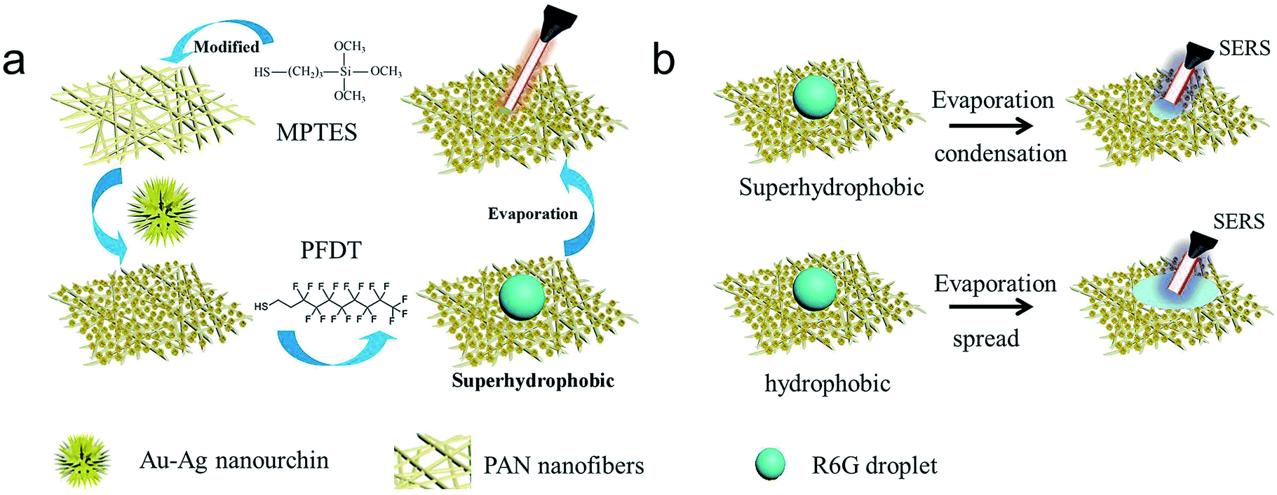 | ||
| Fig. 1 (a) Schematic for the fabrication of grafted PAN/Au–Ag nanourchins nanofiber membranes. (b) Schematic for the evaporating and spreading process of the droplet. | ||
In order to explore the influences of the size and morphology of noble metal on the superhydrophobicity, five different morphologies of the Au nanocrystals had been prepared, which were AuNSs, AuNRs, AuBPs, AuNFs and Au–Ag nanourchins. The morphologies of the nanocrystals were investigated by TEM and SEM. As shown in Fig. 2a and f, uniform AuNSs with an average diameter about 20 nm are well dispersed without aggregations. The average length and width of as-synthesized AuNRs are about 100 and 13 nm respectively (Fig. 2b and g). Fig. 2c and h show that the average length and width of AuBPs are about 100 nm and 40 nm. The as-synthesized AuNFs are quasi-spherical, consisting of a solid Au core with many short, irregular, and obtuse Au nanocrystals. The diameter of AuNFs is about 80 nm (Fig. 2d and i). The individual Au–Ag nanourchin nanoparticle is composed of many sharp protrusions and nanogaps (Fig. 2e and j) with a diameter of 350 nm. These sharp tips of Au–Ag nanourchins not only benefit surface roughness, but also provide more SERS hot spots with strong plasmonic field enhancement.21
 | ||
| Fig. 2 SEM and TEM images of (a and f) AuNSs, (b and g) AuNRs, (c and h) AuBPs, (d and i) AuNFs, (e and j) Au–Ag nanourchins; UV-vis spectra of the (k) AuNSs, (l) AuNRs, (m) AuBPs, (n) AuNFs, (o) Au–Ag nanourchins. | ||
UV-vis spectra of all the nanocrystals are shown in Fig. 2k–o. The surface plasmon resonance (SPR) peak of AuNSs, AuNFs and Au–Ag nanourchins located at 510 nm, 715 nm and 520 nm respectively. The longitudinal SPR peak of the AuNRs and AuBPs is about 870 nm and 840 nm respectively.
Fig. 3 shows the morphologies of a series of electrospun PAN/noble metal nanofibrous mat. SEM images show that the different noble metal nanocrystals were firmly attached to the nanofibrous mat through strong Au–S chemical bonding, which is more stable than the system obtained by physical adsorption alone. SEM images show that PAN/noble metal hybrid mats have many junctions among fibers, and a lot of nanocrystals are densely immobilized on the surface of the fibre membrane. The coarse metal surface with hot spots will be in favour of SERS detection.
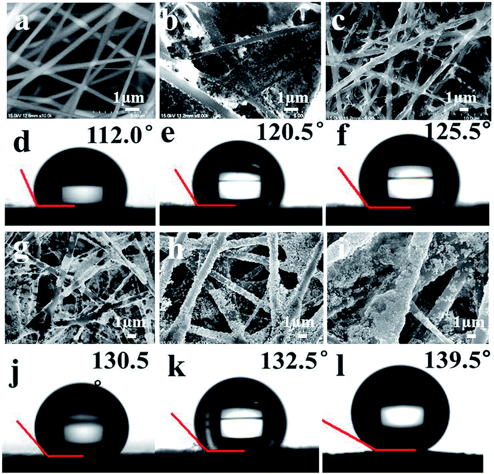 | ||
| Fig. 3 SEM images of (a) pure PAN, (b) PAN/AuNSs, (c) PAN/AuNRs, (d) PAN/AuBPs, (e) PAN/AuNFs, (f) PAN/Au–Ag nanourchins nanofibrous mats; the contact angle of (g) PAN, (h) PAN/AuNSs, (i) PAN/AuNRs (j) PAN/AuBPs, (k) PAN/AuNFs, (l) PAN/Au–Ag nanourchins nanofibrous mats. | ||
The contact angle of pure PAN fibrous mat is about 112.0°. The optimal contact angles of PAN/AuNSs, the PAN/AuNRs, PAN/AuBPs and PAN/AuNFs nanofibrous mats are about 120.5°, 125.5°, 130.5° and 132.5°, respectively (Fig. 3e, f, j and k). In particular, the contact angle of the PAN/Au–Ag nanourchins membrane reached 139.5° (Fig. 3l). We noted that the contact angle of these mats improved with the increased size or surface roughness of Au nanoparticles. The PAN/AuNSs mat shows the lowest contact angle due to the smallest size of AuNSs (only 20 nm). The contact angle of PAN/AuNFs nanofibrous mats is a little higher than that of PAN/AuNRs, PAN/AuBPs mats. We guess that it may be attributed to the much coarser surfaces of AuNFs with more branches. The PAN/Au–Ag nanourchins membrane exhibits the highest contact angle which may be stem from the largest size (∼350 nm) and the much more branch structure of Au–Ag nanourchins compare to other noble metal nanocrystals. In general, the hydrophobicity of the substrate improved with the roughness of the surface increasing. Larger size and more branches structure of Au–Ag nanourchins will benefit to form hierarchical micro–nano structures, getting rise to coarse surface. In addition, relatively serious aggregated Au–Ag nanourchins are emerged on the PAN nanofibrous mat, which are also in favour to the improved roughness, formatting micro–nanostructure and hot spots.11 Note that the superiority of PAN/Au–Ag nanourchins nanofibrous mat for the roughness and high hot spots, we chose PAN/Au–Ag nanourchins nanofibrous mat for further SERS measurements.
Previous reports indicated that rough surface and low surface energy are indispensable for the formation of superhydrophobic surfaces.22 Typically, two approaches have been developed to prepare superhydrophobic surfaces: one is to increase the surface roughness by constructing micro–nanoscale hierarchical structures;23,24 the other is to modify the surface with a low surface energy material, such as fluoride compounds, mercapto compounds, silanes, etc.6,7,23 In order to further improve the PAN/Au–Ag nanourchins substrate's hydrophobicity, the PAN/Au–Ag nanourchins membrane was immersed into PFDT solution overnight. PFDT are a class of molecules with long-chain alkyl mercaptans which commonly was used to modify the micro–nanoscale hierarchical surface to further decrease the surface energy and afford the surface of the substrate with superhydrophobic characteristic. As shown in Fig. 4a, the contact angle of the PAN/Au–Ag nanourchins membrane after chemical modification reached 151°, demonstrating that the surface of PAN/Au–Ag nanourchins membrane exhibited superhydrophobicity. The EDX spectrum also infers the existence of element Si, F and, Au–S bonding on the membrane surface (Fig. 4b).
 | ||
| Fig. 4 (a) SEM image of PAN/Au–Ag nanourchins nanofibrous mat. Inset is the contact angle of the membrane after chemical modification with PFDT. (b) EDX spectrum of the PAN/Au–Ag nanourchins nanofibrous mat. | ||
It is worth noting that the droplet on modified PAN/Au–Ag nanourchins membrane became considerably stable during the evaporation process and the shrinking droplet still maintains its spherical shape without spreading out after 10 min (Fig. 5a). However, the droplet on pure PAN nanofibrous mat collapsed quickly and eventually spread over a very large area on the surface of membrane (Fig. 5b). The stability of the droplet on the superhydrophobic substrate ensures the analyte molecules are effectively enriched on a very small confined area during evaporation.
 | ||
| Fig. 5 The evolution of the contact angles on the membranes with the time increasing. (a) PAN/Au–Ag nanourchins substrate. (b) Pure PAN substrate. | ||
In order to compare the different enhancement effects between the superhydrophobic substrate and non-superhydrophobic substrate, we prepared two PAN/Au–Ag nanourchins nanofibrous mats with different contact angle. R6G was used as probing molecules for the SERS measurements to study the Raman enhancement effect of the PAN/Au–Ag nanourchins nanofibrous mat. R6G droplets were dropped on the surface of the nanofibrous mats.
When the droplet was deposited on a non-superhydrophobic surface with a low contact angle (121°), the droplet readily collapsed and resulted in the spreading of the droplet over a much larger area, about 27 mm2 (Fig. 6a and b). However, the droplet could not wet the superhydrophobic surface (151°), and only a very small solid–liquid contact area was observed. Finally, the droplet was effectively concentrated on a 2 mm2 area after evaporation (Fig. 6d and e). Subsequently, SERS spectra of different concentration of R6G solution on the PAN/Au–Ag nanourchins nanofibrous mats were collected. The strong Raman signals of R6G molecules at 1650, 1564, 1597, 1509, 1360, 1281, 1184 cm−1 were detected respectively. In detail, the peaks at 1360, 1509, 1564 and 1650 cm−1 are assigned as aromatic C–C stretching; the peak at 1281 cm−1 are assigned as C–C bridge-bands stretching. The positions and intensities of Raman peaks vs. the concentration of R6G were listed in Fig. S1.† Apparently, the intensities of the Raman signals of R6G on the non-superhydrophobic surface are much weaker than that on the superhydrophobic surface. For the non-superhydrophobic surface, the intensity of Raman of R6G molecules reduced with the decreasing of R6G concentrations ranging from 10−2–10−5 M. The Raman signal of 10−5 M R6G is already very weak (Fig. 6c). Whereas, for the superhydrophobic PAN/Au–Ag nanourchins nanofibrous mat, the peak intensity of 10−7 M R6G is still very strong and the Raman signals of 10−13 M R6G molecules on superhydrophobic surface could be detected clearly (Fig. 6f). In this work, the volume of droplet for detection is 15 μL. When the volume of droplet is too large, the droplet will spread over a larger area. When the volume is too small, it is difficult to find the imprint of droplet after evaporation.
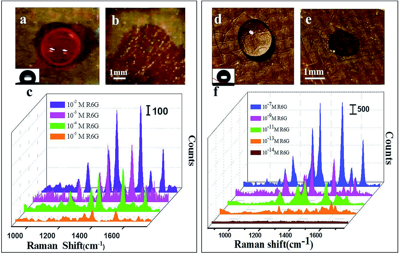 | ||
| Fig. 6 (a) Photographs of water droplet on the hydrophobic PAN/Au–Ag nanourchins nanofibrous mat with low contact angle (121°); (b) the spot area of water droplet after evaporation; (c) SERS spectra of R6G (10−2–10−5 M) absorbed on hydrophobic PAN/Au–Ag nanourchins nanofibrous mat. (d) Photographs of water droplet on the superhydrophobic PAN/Au–Ag nanourchins nanofibrous mat nanofibrous mats with high contact angle (151°); (e) the spot area of water droplet after evaporation; (f) SERS spectra of R6G (10−7–10−14 M) absorbed on superhydrophobic PAN/Au–Ag nanourchins nanofibrous mat. | ||
The above results indicated that the trace detection on the superhydrophobic surface would dramatically decrease the SERS trace detection concentration, as compared with that on the hydrophobic surface. The superiority for SERS trace detection on PAN/Au–Ag nanourchins nanofibrous mat can be attributed to the synergetic effect between improved roughness, more “hot spots” at junction positions and condensation effect induced by superhydrophobicity.
4. Conclusion
In conclusion, we prepared a series of PAN/noble metal hybrid nanofibers via electrospinning technique followed by the layer by layer self-assembly. Au–Ag nanourchins with large size and more tips benefit the formation of hierarchical micro–nanostructures as well as the superhydrophobic characteristic of the substrate and also can provide more hot spots with strong plasmonic field enhancement. The superhydrophobic substrate can drive and enrich analyte molecules over a small confined area. Highly sensitive SERS trace detection for R6G with detection limit as low as 10−13 M was achieved on the PAN/Au–Ag nanourchins nanofibrous mat, leading to a 8-fold improvement in the lowest detection concentration for R6G molecules in comparison with that on non-superhydrophobic substrate. Superhydrophobic substrate proves to high SERS-sensitive substrate for the trace detection of analyte molecules.Conflicts of interest
There are no conflicts to declare.Acknowledgements
This work was supported by the National Natural Science Foundation of China (51573121), a project funded by the Open Project Program of Key Laboratory of Eco-textiles, Ministry of Education, Jiangnan University (No. KLET1507), a project funded by the Priority Academic Program Development of Jiangsu Higher Education Institutions and State and Local Joint Engineering Laboratory for Novel Functional Polymeric Materials.References
- G. C. Phan-Quang, H. K. Lee, I. Y. Phang and X. Y. Ling, Angew. Chem., 2015, 127, 9827–9831 CrossRef.
- F. De Angelis, F. Gentile, F. Mecarini, G. Das, M. Moretti, P. Candeloro, M. Coluccio, G. Cojoc, A. Accardo and C. Liberale, Nat. Photonics, 2011, 5, 682–687 CrossRef CAS.
- H. K. Lee, Y. H. Lee, I. Y. Phang, J. Wei, Y. E. Miao, T. Liu and X. Y. Ling, Angew. Chem., 2014, 126, 5154–5158 CrossRef.
- L. Shao, Y. Tao, Q. Ruan, J. Wang and H.-Q. Lin, Phys. Chem. Chem. Phys., 2015, 17, 10861–10870 RSC.
- H. J. Chen, L. Shao, Q. Li and J. F. Wang, Chem. Soc. Rev., 2012, 42, 2679–2724 RSC.
- H. K. Lee, Y. H. Lee, Q. Zhang, I. Y. Phang, J. M. R. Tan, Y. Cui and X. Y. Ling, ACS Appl. Mater. Interfaces, 2013, 5, 11409–11418 CAS.
- H. Zhao, J. Jin, W. Tian, R. Li, Z. Yu, W. Song, Q. Cong, B. Zhao and Y. Ozaki, J. Mater. Chem. A, 2015, 3, 4330–4337 CAS.
- X. Wang, B. Ding, J. Yu and M. Wang, Nano today, 2011, 6, 510–530 CrossRef CAS.
- J. l. Sheng, Y. Xu, J. Y. Yu and B. Ding, ACS Appl. Mater. Interfaces, 2017, 9, 15139–15147 CAS.
- M. H. Tai, P. Gao, B. Y. L. Tan, D. D. Sun and J. O. Leckie, ACS Appl. Mater. Interfaces, 2014, 6, 9393–9401 CAS.
- M. Ma, M. Gupta, Z. Li, L. Zhai, K. K. Gleason, R. E. Cohen, M. F. Rubner and G. C. Rutledge, Adv. Mater., 2007, 19, 255–259 CrossRef CAS.
- M. H Cao, L. Zhou, X. Q. Xu, S. Cheng, J.-L. Yao and L.-J. Fan, J. Mater. Chem. A, 2013, 1, 8942–8949 Search PubMed.
- X. F. Li, M. H Cao, H. Zhang, L. Zhou, S. Cheng, J.-L. Yao and L.-J. Fan, J. Colloid Interface Sci., 2012, 382, 28–35 CrossRef CAS PubMed.
- P. Jia, B. Cao, J. Wang, J. Qu, Y. Liu and K. Pan, Analyst, 2015, 140, 5707–5715 RSC.
- P. Jia, J. Chang, J. Wang, P. Zhang, B. Cao, Y. Geng, X. Wang and K. Pan, Chem.–Asian J., 2016, 11, 86–92 CrossRef CAS PubMed.
- P. Jia, J. Qu, B. Cao, Y. Liu, C. Luo, J. An and K. Pan, Analyst, 2015, 140, 5190–5197 RSC.
- H. Chen, X. Kou, Z. Yang, W. Ni and J. Wang, Langmuir, 2008, 24, 5233–5237 CrossRef CAS PubMed.
- H. Zhang, Z. Liu, X. Kang, J. Guo, W. Ma and S. Cheng, Nanoscale, 2016, 8, 2242–2248 RSC.
- X. Kang, Q. Ruan, H. Zhang, F. Bao, J. Guo, M. Tang, S. Cheng and J. Wang, Nanoscale, 2017, 9, 5879–5886 RSC.
- W. Ma, M. Sun, L. Xu, L. Wang, H. Kuang and C. Xu, Chem. Commun., 2013, 49, 4989–4991 RSC.
- Z. Liu, Z. Yang, B. Peng, C. Cao, C. Zhang, H. You, Q. Xiong, Z. Li and J. Fang, Adv. Mater., 2014, 26, 2431–2439 CrossRef CAS PubMed.
- F. Gentile, M. L. Coluccio, R. P. Zaccaria, M. Francardi, G. Cojoc, G. Perozziello, R. Raimondo, P. Candeloro and E. Di Fabrizio, Nanoscale, 2014, 6, 8208–8225 RSC.
- L. Feng, Z. Zhang, Z. Mai, Y. Ma, B. Liu, L. Jiang and D. Zhu, Angew. Chem., Int. Ed., 2004, 43, 2012–2014 CrossRef CAS PubMed.
- B. Wang, W. Liang, Z. Guo and W. Liu, Chem. Soc. Rev., 2015, 44, 336–361 RSC.
Footnotes |
| † Electronic supplementary information (ESI) available. See DOI: 10.1039/c7ra09194j |
| ‡ Xiaohong Liang and Han Zhang contributed equally to this work. |
| This journal is © The Royal Society of Chemistry 2017 |