 Open Access Article
Electrospray-mediated preparation of compositionally homogeneous core–shell hydrogel microspheres for sustained drug release
Wing-Fu Lai *ab,
Andrei S. Sushac,
Andrey L. Rogach
 c,
Guoan Wanga,
Minjian Huanga,
Weijie Hua and
Wing-Tak Wong*b
aSchool of Pharmaceutical Sciences, Health Science Centre, Shenzhen University, Shenzhen, China
bDepartment of Applied Biology and Chemical Technology, The Hong Kong Polytechnic University, Hong Kong. E-mail: rori0610@graduate.hku.hk; w.t.wong@polyu.edu.hk
cDepartment of Materials Science and Engineering & Centre for Functional Photonics (CFP), City University of Hong Kong, Hong Kong
First published on 15th September 2017
Abstract
Incorporating hydrogel particles with the core–shell architecture is a promising route to fabricate colloidal “smart gels” with tuneable properties. This study reports a facile electrospray-based method to generate compositionally homogeneous core–shell hydrogel microspheres. By manipulating different process parameters (e.g., electric field strength, flow rate, and gel-forming polymer concentration), the size of the microspheres can be tuned from microns to millimetres. Drug release studies demonstrate that coating the surface of the hydrogel microsphere with a hydrogel layer remarkably prolongs the drug release sustainability. In 3T3 and HEK293 cells, both the acute and delayed toxicity caused by the hydrogel microspheres are shown to be negligible. Together with the ease of operation of the production method, the compositionally homogeneous core–shell microspheres generated by our method may enhance the versatility and flexibility in future drug delivery.
1. Introduction
Hydrogels are three dimensional hydrophilic polymer networks, which on the one hand can absorb a substantial amount of fluids and on the other hand are resistant to dissolution.1 This is ascribed to the presence of cross-links among the polymer chains, as well as to the availability of hydrophilic functional groups attached to the polymeric backbone.2 Over the years, hydrogels have played an important role in drug delivery research due to their advantages over many other drug carriers. For instance, compared to emulsions whose potential use as drug carriers is commonly impeded by the surfactant toxicity and droplet coalescence,3 hydrogels are relatively stable and biocompatible. In comparison with liposomes,4–6 whose production process is often time-consuming and involves the use of volatile organic solvents, hydrogels can be generated simply in an all-aqueous environment. The encouraging practical potential of hydrogels in drug delivery has already been evidenced in the preclinical context.7–15Since the turn of the last century, the development of core–shell hydrogel particles has received an increasing amount of research attention because incorporating particles with the core–shell architecture is one of the promising routes to fabricate colloidal “smart gels” with tuneable properties.16 Till now diverse methods for the production of core–shell hydrogel particles have been reported, ranging from seed and feed precipitation polymerization17 to surfactant-free emulsion polymerization.18 Other methods such as epitaxy have also been investigated for the generation of microspheres with the core–shell structure.19 Notwithstanding these advances, most of the reported methods either necessitate the use of bulky and complicated instrumental apparatuses, or involve chemical cross-linking during the process. The former has made proper translation of the reported methods to practical settings difficult; whereas the latter has subjected the loaded drugs to side reactions that may inactivate the therapeutic activity. There is an urgent need for a search of simple methods to manipulate the microstructure of hydrogel particles while enabling minimal interference in the therapeutic action of the loaded drug.
We have previously adopted the microfluidic electrospray technology to successfully manipulate the microstructure of hydrogel particles to generate multicompartment microgels for co-delivery of incompatible agents.20 With the use of light-emitting cadmium telluride (CdTe) quantum dots (QDs) and poly(ethylenimine) (PEI) as a model pair, the microgels have been shown to be able to partition different agents in separate compartments to minimize the interactions between the co-delivered agents during the delivery process. The drug release sustainability in different compartments of a bead has also been demonstrated to be tuneable by manipulating the hydrogel composition to modulate the release profiles of the co-delivered agents.20 In this study, we further extend the capacity of microfluidic electrospray, and develop a novel yet facile method for the fabrication of compositionally homogeneous core–shell hydrogel microspheres. The size of the microspheres can be tuned by simply adjusting the flow rate, the solution concentration and the electric field strength. Our approach enables easy generation of core–shell microspheres with homogenous composition for a wide range of drug delivery applications.
2. Materials and methods
2.1 Materials
Carboxymethylcellulose (CMC) (sodium salt, Mw = 250 kDa, 1500–3100 cP, degree of substitution = 1.2) was obtained from Aladdin (Shanghai, China). Methylene blue (MB), calcium chloride (CaCl2), 3-mercaptopropionic acid (MPA), tetracycline hydrochloride (TH), alginic acid (Alg) (sodium salt from brown algae), and various other chemicals were purchased from Sigma-Aldrich (St. Louis, MO, USA). Dulbecco's Modified Eagle's Medium (DMEM; Gibco, Grand Island, NY), penicillin G-streptomycin sulphate (Life Technologies Corporation. USA), and fetal bovine serum (FBS; Hangzhou Sijiqing Biological Engineering Materials Co., Ltd., China) were used as the cell culture medium. Trypsin–EDTA (0.25% trypsin–EDTA) was obtained from Invitrogen.2.2 Synthesis of CdTe QDs
CdTe QDs were synthesized according to a previously reported protocol with slight modifications.21 Briefly, a three-necked flask with 50 mL of distilled water was degassed by N2 bubbling for 20 min. After that, 1 mmol of cadmium acetate dehydrate and 400 mL of distilled water were added, followed by the addition of 1.12 mmol of MPA. The pH of the reaction mixture was adjusted to 10.5 by using a 1 M sodium hydroxide solution. 50 mL of a sodium tellurite solution (0.44 mg mL−1) containing 10 mmol of sodium borohydride were added into the solution mixture. The reaction mixture was refluxed at 100 °C under open-air conditions. After reaction, CdTe QDs were purified by two precipitation–washing–centrifugation cycles with isopropyl alcohol. The purified CdTe QDs were finally re-dispersed in deionized water, and stored at 4 °C for subsequent use.2.3 Fabrication of the capillary microfluidic device
Cylindrical capillaries (World Precision Instrument Inc.), having an inner and outer diameter of 0.58 mm and 1 mm, were tapered using a micropipette puller (P-97, Sutter Instrument, Inc.). The tips of the capillaries were polished to a diameter of 500 μm using a sand paper.2.4 Preparation of hydrogel microspheres
CMC was dissolved in distilled water to prepare a 4% w/v solution. The solution was driven by syringe pumps (Model LSP01-2A, Baoding Longer Precision Pump Co., Ltd.). A high-strength electric field was formed between the nozzle and a ground circular electrode connected to a high voltage power supply. By increasing the electric field strength, the solution was ionized, and a tapered tip driven by the electrostatic force was formed. Afterwards, the jet with the tapered tip shape broke up into micro-droplets in the high-strength electric field. The droplets of the CMC solution were collected in a collection bath, in which a 3% w/v CaCl2 solution was added. The calcium ions (Ca2+) cross-linked the micro-droplets to form microspheres.By replacing the CMC solution with an Alg solution, the same procedure was applied to generate hydrogel microspheres from Alg. To load light-emitting QDs or model drugs into the microspheres, a gel-forming solution was first mixed with CdTe QDs, MB or TH to a final concentration of 1% (w/v), before the solution was subjected to the electrospray process. To fabricate microspheres with the core–shell architecture, 3 mL of a drug-loaded polymer solution were first adopted to generate hydrogel microspheres, which were then suspended in an aqueous solution of an appropriate gel-forming polymer. The suspension obtained was introduced into the capillary microfluidic device, followed by the repetition of the procedure employed to generate the hydrogel microspheres in the first place.
2.5 Microscopic evaluation of the microspheres
CMC-based hydrogel microspheres were prepared at different flow rates (950, 1000, 1500, 2000 and 2500 μL h−1) and electric field strength values (2.5, 5, 7.5 and 10 kV cm−1). The morphology of the microspheres, as well as their size, has been examined under an inverted microscope (Eclipse Ti-U, Nikon, Japan). Grayscale microscopic images were acquired using a CCD camera (CoolSNAP HQ2, Photometrics, USA) attached to the microscope. Image J was used to analyze the size of the microspheres. The size recorded was an average of 10 measurements.2.6 Viscosity measurements
Viscosity measurements were made using a viscometer (μVISC; RheoSense, San Ramon, CA, USA) at ambient conditions according to the manufacturer's instructions. The B10 μVISC chip (60–5000 cP, 100 μm flow channel) was used for all measurements.2.7 Determination of the drug encapsulation efficiency
After the formation of drug-encapsulated hydrogel microspheres, the CaCl2 solution was collected from the collection bath. The concentration of the un-encapsulated model drug (viz., MB and TH) was determined using a UV/vis spectrophotometer (Varian, Inc., USA) as previously described.22 The drug encapsulation efficiency was calculated using the following equation:
 | (1) |
2.8 Drug release evaluation
Drug-encapsulated microspheres were generated from 3 mL of a drug-loaded polymer solution. After that, the CaCl2 solution from the collection bath was removed, and 5 mL of phosphate buffer saline (PBS, pH = 7.4) were added to the microspheres. At a pre-set time interval, 1 mL of the buffer solution was removed for testing, and was replaced with 1 mL of PBS. The amount of the drug released from the microspheres was determined using a UV/vis spectrophotometer (Varian, Inc., USA) as previously described.22 The cumulative drug release was calculated using the following formula:
 | (2) |
2.9 Cytotoxicity assay
HEK 293 and 3T3 fibroblast cells were purchased from ATCC, and were cultured in the DMEM medium containing 10% FBS, 100 UI mL−1 penicillin, 100 μg mL−1 streptomycin, and 2 mM L-glutamine. 24 hours before the assay, the cells were seeded in 96-well plates at an initial density of 5000 cells per well, and were incubated at 37 °C and 5% CO2. When the assay was performed, the growth medium was replaced with 100 μL of the fresh cell culture medium with or without 10% FBS. 10 μL of a solution containing different amounts (0, 0.25, 0.5, 0.75, 1, 1.25, 1.5, 1.75, and 2 μg) of the lyophilized microspheres were added to each well. After 5 hours of incubation at 37 °C, the cell medium was replaced with 100 μL of the fresh growth medium. The Cell Titer 96 Aqueous One solution cell proliferation assay (MTS assay; Promega Corp., Madison, WI) was then performed either immediately or after 24 hours of post-treatment incubation of the cells. Assays were performed according to the manufacturer's instructions. The cell viability (%) in each well was determined by dividing the absorbance value (A490) of the test well by the A490 value of the control well, followed by a multiplication of the quotient by 100%.2.10 Statistical analysis
All data were presented as the means ± standard deviations of triplicate experiments. Student's t-test was performed to assess the statistical significance. Differences with a p-value < 0.05 were considered to be statistically significant.3. Results
3.1 Fabrication of hydrogel microspheres
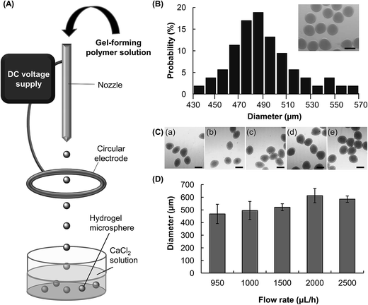
Microfluidic electrospray is a technique for the generation of aerosols via electrostatic dispersion of liquids.23 In this study, this technique is adopted to fabricate hydrogel microspheres. By using this approach, a CMC solution supplied by a syringe pump is dispersed into droplets by an electric field (Fig. 1A). The droplets are collected by a collection tray in which the counterion (Ca2+) is present, and then undergo ionic gelation to form hydrogel microspheres. During the process of microfluidic electrospray, break-up of the bulk solution into fined charged droplets is a result of the interplay among the liquid/air surface tension, the gravitational force, and the electrostatic force (Fe).24 Such a process has been described by an electrochemical model.25 Microscopic evaluation reveals that the diameter of the CMC microspheres fabricated by a 4% w/v CMC solution (flow rate = 1500 μL h−1, electric field strength = 5 kV cm−1) is in a range of 430–570 μm (Fig. 1B). The average diameter is 490 μm, and the polydispersity is approximately 5.8%.3.2 Adjustment of the size of microspheres
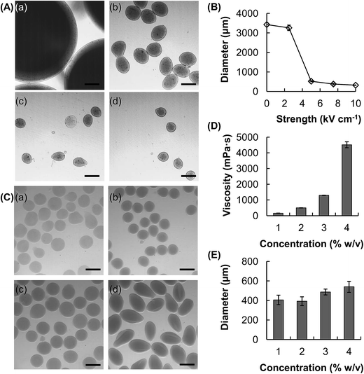
The size of the hydrogel microspheres can be adjusted by changing the flow rate. We fabricate microspheres using five different flow rates while keeping the electric field strength constant (Fig. 1C and D). The size of the microspheres increases from around 470 μm to 590 μm as the flow rate increases from 950 μL h−1 to 2500 μL h−1. The electric field strength is another parameter which can be adjusted to change the size of the microspheres (Fig. 2A and B). In the absence of an electric field between the circular electrode and the nozzle, the size of the microsphere attained (4% w/v CMC solution, flow rate = 1500 μL h−1) is over 3.4 mm. Upon the application of an electric field, the size of the microspheres decreases. At the electric field strength of 5 kV cm−1, the diameter of the hydrogel microspheres is around 520 μm, which is roughly 7 times as small as that attainable in the absence of the electric field.In addition to tuning the flow rate and the electric field strength, changing the concentration of the CMC solution may modulate the droplet formation process and hence the size of the microspheres formed (Fig. 2C–E). With an increase in the CMC concentration from 1 to 4%, the viscosity increases by more than an order of magnitude, from 157 to 4514 mPa s (Fig. 2D). The size of the generated microspheres also increases from 400 μm to around 550 μm (Fig. 2E). Our results reveal that an increase in the viscosity of a solution leads to an increase in the size of the droplet formed, and hence the size of the microsphere formed.
3.3 Generation of core–shell microspheres and drug release evaluation
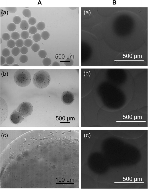
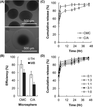
By using a facile electrospray-based approach, compositionally homogeneous microspheres with the core–shell architecture are successfully generated (Fig. 3A). In addition to coating the CMC-based hydrogel core with a CMC-based hydrogel shell to generate CMC/CMC (C/C) core–shell microspheres, the same method is applied to coat the surface of the CMC-based hydrogel core with an Alg-based hydrogel layer to produce CMC/Alg (C/A) microgels. Intriguingly, by adjusting the volume of the polymer solution used to resuspend the generated microspheres, the method offers flexibility to microsphere fabrication by enabling the generation of C/A microgels with multiple cores (Fig. 3B). The CMC-based hydrogel microspheres have the drug encapsulation efficiency of around 80% for TH and 60% for MB (Fig. 4A and B). The encapsulation efficiency slightly drops after incorporation of the hydrogel shell, reasonable drug encapsulation efficiency (around 60% for TH and 30% for MB) remains. This renders our facile electrospray-based method applicable to drug loading in practice.As revealed by the release profiles of TH from the microspheres (Fig. 4C), while 90% or above of the encapsulated drug is released within the first 2.5 hours from the conventional CMC-based microgels, the time to reach the same level of cumulative drug release is extended to 30 hours when the core–shell C/A hydrogel microspheres are used. This suggests that incorporation of the Alg-based hydrogel shell significantly decreases the drug release rate, and extends the drug release sustainability 12-fold as much as that achieved by the uncoated counterparts. To demonstrate the tunability of the drug release sustainability of the C/A microspheres, the composition of the hydrogel shell is modulated by incorporating with different amounts of CMC. As shown in Fig. 4D, the drug release rate is in a negative relationship with the Alg/CMC mass-to-mass ratios of the hydrogel shell of the C/A microspheres.
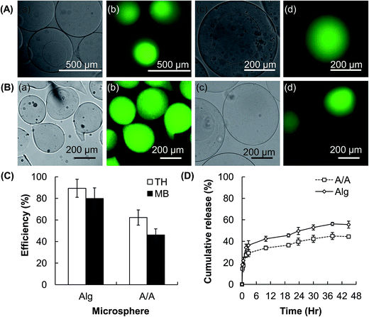
In addition to CMC, we have applied our method to Alg, which is a polymer similar to CMC in a way that physical hydrogels can be formed by ionic gelation, to examine the transferability of our reported method to other hydrogel systems. Compositionally homogeneous Alg/Alg (A/A) core–shell hydrogel microspheres are successfully fabricated (Fig. 5A). The TH and MB encapsulation efficiency of the uncoated Alg-based microgels is 90% and 80%, respectively. Although some of the encapsulated drug is lost during the processing of the hydrogel cores into core–shell microspheres, the drug encapsulation efficiency of the core–shell particles is still as high as 50–60% (Fig. 5B and C). In addition, compared to the uncoated counterparts, the A/A microspheres exhibit much higher drug release sustainability. After 48 hours of post-incubation, the amount of TH released from the A/A microspheres is only 80% of the total amount of TH released from the conventional Alg-based hydrogel microspheres (Fig. 5D).
3.4 Toxicity of hydrogel microspheres
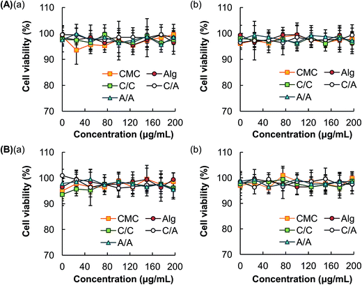
Immediately after treatment with various concentrations of different types of hydrogel microspheres, no observable loss of cell viability is detected. This indicates the lack of acute cytotoxicity of the hydrogel microspheres (Fig. 6). The delayed cytotoxic effect of the microspheres is examined by incubating the cells at 37 °C for additional 24 hours before the MTS assay is performed. The loss of cell viability is also found to be negligible.4. Discussion
Hydrogels are highly biocompatible in general, and have been widely exploited as drug carriers over the years.1,26–28 Compared to chemical hydrogels, physical hydrogels possess a number of favourable properties,29 including lower toxicity and better reservation of drug actions. The latter is attributed to the fact that chemical or photochemical triggering is not required for hydrogel formation. Therefore, not only structural changes potentially introduced to the loaded drug can be minimized,30,31 but the loading process can also be simpler and more efficient.31 A common method to generate physical hydrogels is ionic gelation, in which hydrogels are formed by means of electrostatic interactions between the polymer chains and the oppositely charged ions. Alg and CMC are selected in this study as the starting materials for hydrogel formation because these polymers possess a number of favourable properties (e.g., high chemical stability, high aqueous solubility, and good biocompatibility)32,33 and have a track record of applications in diverse areas, ranging from food production to drug delivery.34–37The method reported in this study for the fabrication of core–shell hydrogel microspheres is partly based on the use of electrospray,23 which has been adopted in a previous study to produce hydrogel beads from Alg for delivery of paclitaxel-loaded polymeric particles.38 In this study, we incorporate capillary microfluidics into the electrospray technology to develop a facile method for the production of compositionally homogeneous core–shell hydrogel microspheres (Fig. 1), which can hardly be fabricated using strategies reported in the existing literature.18,39–42 One favourable aspect of our reported method is the capacity of fine-tuning the size of the microspheres. This can be achieved by simply altering the process parameters such as the electric field strength, whose magnitude is shown to be in a negative relationship with the size of the microspheres generated. In the absence of an electric field between the circular electrode and the nozzle, droplet formation is driven mainly by the interplay between surface tension and gravity. The size of the microspheres attained (4% w/v CMC solution, flow rate = 1500 μL h−1) is over 3.4 mm (Fig. 2). However, when an electric field is applied, the increasing electrostatic force stretches the fluid dispensed through the nozzle, and a tapered jet is resulted. The size distribution of the microspheres usually is broad when the electrostatic force is comparable to the gravitational force. This is because such a condition results in an unstable fluctuating jet and hence the formation of satellite droplets during jet breakup. As the electric field strength increases, the electrostatic force, rather than the gravitational force, dominates the pulling force against surface tension. This forms a stable tapered jet, leading to more monodisperse droplet formation. The size of the microspheres formed at the electric field strength of 5 kV cm−1 is approximated to be 520 μm, which is roughly 7 times as small as that attainable in the absence of an electric field.
Apart from modulating the electric field strength, the droplet formation process and hence the size of the microspheres may be tuned by manipulating the flow rate as well as the concentration of the gel-forming polymer solution (Fig. 1 and 2). The latter is revealed by the observation that with an increase in the concentration of the CMC solution from 1 to 4%, viscosity increases by more than an order of magnitude, from 157 to 4514 mPa s. As reported in an earlier study, an increase in viscosity results in an increase in resistance of jet breakup and hence droplet formation.43 The effect of the viscosity of the solution to droplet formation can be estimated using a dimensionless number πμ:44
 | (3) |
Apart from forming conventional microgels, core–shell hydrogel microspheres can be generated by re-suspending the microgels into a gel-forming polymer solution, followed by re-introduction of the suspension into the microfluidic electrospray device. This facile method is successfully used to generate C/C, C/A, and A/A microspheres (Fig. 3–5). In addition to generating core–shell hydrogel particles with one core (Fig. 3A), we observe that by reducing the volume of the polymer solution used to resuspend the generated microgels, the rate of appearance of microspheres with two or more hydrogel cores increases (Fig. 3B). Although further development and optimization of the method are required before the production of multi-core microspheres can be precisely controlled in practice, the viability of the method to fabricate multi-core microgels may show future potential in drug delivery for multi-drug therapy, whose execution has now been limited by the incompatibility problem arisen from co-delivered drugs. This problem has been reported in a previous study, which has co-delivered a plasmid with a chemotherapeutic drug using a polymeric vector and has found that the action of the chemotherapeutic drug has substantially suppressed the expression of the transgene.46 The findings from that study have evidenced that interactions of co-delivered agents can substantially reduce the efficiency of multi-drug therapy. Our core–shell microspheres with multiple cores might help to solve this problem by separating the drugs in different regions during the delivery process. The efficiency and viability of such an approach in tackling the incompatibility problem has already been verified in our previous study, in which interactions of incompatible agents have been prevented when those agents are isolated in different compartments in one single system.20
To assess the performance of the microspheres generated by our method as drug carriers, TH and MB are used as model drugs. These drugs have been extensively used in the literature for studies in drug delivery.47,48 The CMC-based hydrogel microspheres show the drug encapsulation efficiency of around 80% for TH and 60% for MB (Fig. 4). The efficiency slightly drops after the microspheres have been incorporated with the core–shell architecture. This is ascribed to the fact that the gel-forming polymer is in the form of a sodium salt. The release of the loaded drug is triggered when the microspheres are re-suspended in the polymer solution. This phenomenon has been supported by the previous observation that Alg-based hydrogel particles experience a higher rate of drug release in an NaCl solution than in distilled water.49 Despite this, reasonably high drug encapsulation efficiency (30–60%) remains, and such efficiency is even higher in the case of A/A microspheres (Fig. 5). This demonstrates that our electrospray-based method is applicable to drug encapsulation in practice.
The capacity of sustaining drug release is another factor pivotal to the functioning of a drug carrier. The rate of drug release from hydrogels is affected by the polymer constituent, which affects the swelling and erosion profiles of the hydrogel system. The equilibrium swollen state of a hydrogel is a result of the balance of diverse forces, including the osmotic pressure, capillary forces, hydration forces, and the force exerted by the cross-linked polymer chains to resist expansion of the hydrogel.50 Based on the drug release profiles of the CMC-based microgels (Fig. 4), incorporation of an Alg-based hydrogel coating can prolong the process of drug release. This is explained by the fact that the swelling capacity of Alg is lower than that of CMC.20 As water in the hydrogel network is the medium through which drug molecules diffuse,51 swelling is one of the important parameters determining the release rate of the encapsulated drug. Incorporation of a hydrogel shell with a lower degree of swelling may help to restrain the swelling and erosion of the CMC-based hydrogel cores (Fig. 4). This proposed mechanism is supported by the success of tuning the drug release sustainability of the core–shell microspheres by altering the Alg/CMC ratio of the hydrogel shell. Such tunability is expected to be mediated by changes in the swelling capacity of the shell upon incorporation of different amounts of CMC. Apart from restricting the swelling of the core, the presence of a shell may enhance the drug release sustainability by lengthening the diffusion distance of drug molecules. This is confirmed by the observation that although the core and the shell of A/A microspheres are the same in composition, a much more sustained release profile is still achieved as compared to that achieved by the uncoated counterparts (Fig. 5).
Last but not least, low toxicity is a critical property of a drug carrier. The high safety profile of the microspheres generated by our method is confirmed by MTS assays in 3T3 mouse fibroblasts and HEK293 cells (Fig. 6). HEK293 is chosen because it is one of the most extensively used cell lines in drug toxicology studies,52 especially in evaluating the nephrotoxicity of a drug candidate.53 3T3 mouse fibroblasts are non-specific cells which also have a track record of use in cytotoxicity tests.54 Our results indicate that both acute and delayed toxicity exhibited by the microspheres are negligible. This renders the microspheres applicable to be further developed as well-tolerated drug delivery systems.
5. Conclusions
Generation of hydrogel microspheres with the core–shell architecture has attracted extensive research interests due to its prospects of facilitating the development of colloidal gels with tuneable properties. This study reports on the use of a novel yet facile electrospray-based method for the production of compositionally homogeneous core–shell microspheres. Our results show that the size and the drug release sustainability of the microspheres can be tuned easily by manipulating the process parameters and the composition of the hydrogel shell. Regarding the tunability and negligible toxicity of the microgels, as well as the ease of operation of the fabrication method, our system has provided a platform upon which further development of core–shell particulate systems with higher flexibility in compositional possibilities may be established.Conflicts of interest
The authors report no conflicts of interest in this work. The authors alone are responsible for the content and writing of the paper.Acknowledgements
The authors would like to thank Guoxing Deng, Fanyue Meng, Xiaoxin Cai, Jieling Li, and Jinzheng Chen for helpful comments and suggestions. This project was supported by the University Research Facility for Chemical and Environmental Analysis (UCEA) of PolyU, HK Polytechnic University Area of Excellent Grants (1-ZVGG), and Natural Science Foundation of Shenzhen University (grant no. 2017092).References
- W. F. Lai and Z. D. He, J. Controlled Release, 2016, 243, 269–282 CrossRef CAS PubMed.
- E. M. Ahmed, J. Adv. Res., 2015, 6, 105–121 CrossRef CAS PubMed.
- C. X. Zhao, Adv. Drug Delivery Rev., 2013, 65, 1420–1446 CrossRef CAS PubMed.
- S. P. Vyas and K. Khatri, Expert Opin. Drug Delivery, 2007, 4, 95–99 CrossRef CAS PubMed.
- G. K. Khuller, M. Kapur and S. Sharma, Curr. Pharm. Des., 2004, 10, 3263–3274 CrossRef CAS PubMed.
- D. S. Mahrhauser, G. Reznicek, S. Gehrig, A. Geyer, M. Ogris, R. Kieweler and C. Valenta, Eur. J. Pharm. Biopharm., 2015, 97, 90–95 CrossRef CAS PubMed.
- R. Tripathi and B. Mishra, AAPS PharmSciTech, 2012, 13, 1091–1102 CrossRef CAS PubMed.
- W. K. Bae, M. S. Park, J. H. Lee, J. E. Hwang, H. J. Shim, S. H. Cho, D. E. Kim, H. M. Ko, C. S. Cho, I. K. Park and I. J. Chung, Biomaterials, 2013, 34, 1433–1441 CrossRef CAS PubMed.
- J. Li, C. Gong, X. Feng, X. Zhou, X. Xu, L. Xie, R. Wang, D. Zhang, H. Wang, P. Deng, M. Zhou, N. Ji, Y. Zhou, Y. Wang, Z. Wang, G. Liao, N. Geng, L. Chu, Z. Qian and Q. Chen, PLoS One, 2012, 7, e33860 CAS.
- R. Pignatello, A. H. Stancampiano, C. A. Ventura and G. Puglisi, J. Drug Targeting, 2007, 15, 603–610 CrossRef CAS PubMed.
- S. Heilmann, S. Kuchler, C. Wischke, A. Lendlein, C. Stein and M. Schafer-Korting, Int. J. Pharm., 2013, 444, 96–102 CrossRef CAS PubMed.
- B. K. Abdul Rasool, E. F. Abu-Gharbieh, S. A. Fahmy, H. S. Saad and S. A. Khan, Trop. J. Pharm. Res., 2010, 9, 355–363 CAS.
- V. Sabale and S. Vora, Int. J. Pharm. Invest., 2012, 2, 140–149 CrossRef CAS PubMed.
- S. Das and U. Subuddhi, Ind. Eng. Chem. Res., 2013, 52, 14192–14200 CrossRef CAS.
- Y. L. Lo, C. Y. Hsu and H. R. Lin, J. Drug Targeting, 2013, 21, 54–66 CrossRef CAS PubMed.
- K. Kim, B. Bae, Y. J. Kang, J. M. Nam, S. Kang and J. H. Ryu, Biomacromolecules, 2013, 14, 3515–3522 CrossRef CAS PubMed.
- D. Gan and L. A. Lyon, J. Am. Chem. Soc., 2001, 123, 7511–7517 CrossRef CAS PubMed.
- L. W. Ma, M. Z. Liu, H. L. Liu, J. Chen and D. P. Cui, Int. J. Pharm., 2010, 385, 86–91 CrossRef CAS PubMed.
- Z. Wen and G. Wang, Sci. Rep., 2016, 6, 25260 CrossRef CAS PubMed.
- W. F. Lai, A. S. Susha and A. L. Rogach, ACS Appl. Mater. Interfaces, 2016, 8, 871–880 CAS.
- H. F. Bao, E. K. Wang and S. J. Dong, Small, 2006, 2, 476–480 CrossRef CAS PubMed.
- W. F. Lai and H. C. Shum, ACS Appl. Mater. Interfaces, 2015, 7, 10501–10510 CAS.
- A. K. Stark, M. Schilling, D. Janasek and J. Franzke, Anal. Bioanal. Chem., 2010, 397, 1767–1772 CrossRef CAS PubMed.
- D. Poncelet, R. J. Neufeld, M. F. A. Goosen, B. Burgarski and V. Babak, AIChE J., 1999, 45, 2018–2023 CrossRef CAS.
- A. M. Gañán-Calvo, Phys. Rev. Lett., 1997, 79, 217–220 CrossRef.
- W. F. Lai and A. L. Rogach, ACS Appl. Mater. Interfaces, 2017, 9, 11309–11320 CAS.
- J. H. Ryu, R. T. Chacko, S. Jiwpanich, S. Bickerton, R. P. Babu and S. Thayumanavan, J. Am. Chem. Soc., 2010, 132, 17227–17235 CrossRef CAS PubMed.
- L. Li, J. H. Ryu and S. Thayumanavan, Langmuir, 2013, 29, 50–55 CrossRef CAS PubMed.
- Y. Tang, C. L. Heaysman, S. Willis and A. L. Lewis, Expert Opin. Drug Delivery, 2011, 8, 1141–1159 CrossRef CAS PubMed.
- X. L. Zhang, J. Huang, P. R. Chang, J. L. Li, Y. M. Chen, D. X. Wang, J. H. Yu and J. H. Chen, Polymer, 2010, 51, 4398–4407 CrossRef CAS.
- D. Sarkar, J. Photochem. Photobiol., A, 2013, 252, 194–202 CrossRef CAS.
- L. Weng, H. C. Le, J. Lin and J. Golzarian, Int. J. Pharm., 2011, 409, 185–193 CrossRef CAS PubMed.
- X. Cai, Y. Luan, Q. Dong, W. Shao, Z. Li and Z. Zhao, Int. J. Pharm., 2011, 419, 240–246 CrossRef CAS PubMed.
- G. Shanker, C. K. Kumar, C. S. Gonugunta, B. V. Kumar and P. R. Veerareddy, AAPS PharmSciTech, 2009, 10, 530–539 CrossRef CAS PubMed.
- S. N. Pawar and K. J. Edgar, Biomaterials, 2012, 33, 3279–3305 CrossRef CAS PubMed.
- D. Jain and D. Bar-Shalom, Drug Dev. Ind. Pharm., 2014, 40, 1576–1584 CrossRef CAS PubMed.
- T. K. Giri, D. Thakur, A. Alexander, Ajazuddin, H. Badwaik and D. K. Tripathi, Curr. Drug Delivery, 2012, 9, 539–555 CrossRef CAS.
- S. H. Ranganath, I. Kee, W. B. Krantz, P. K. Chow and C. H. Wang, Pharm. Res., 2009, 26, 2101–2114 CrossRef CAS PubMed.
- N. Sahiner, S. Butun and P. Ilgin, Colloids Surf., A, 2011, 386, 16–24 CrossRef CAS.
- M. L. Ma, A. Chiu, G. Sahay, J. C. Doloff, N. Dholakia, R. Thakrar, J. Cohen, A. Vegas, D. L. Chen, K. M. Bratlie, T. Dang, R. L. York, J. Hollister-Lock, G. C. Weir and D. G. Anderson, Adv. Healthcare Mater., 2013, 2, 667–672 CrossRef CAS PubMed.
- S. Jenjob, M. Ratanajanchai, N. Mahattanadul, S. Soodvilai and P. Sunintaboon, J. Appl. Polym. Sci., 2014, 131 DOI:10.1002/app.40003.
- N. Devi and D. K. Kakati, Colloid Polym. Sci., 2014, 292, 2581–2596 CAS.
- S. N. Jayasinghe and M. J. Edirisinghe, J. Nanosci. Nanotechnol., 2005, 5, 923–926 CrossRef CAS PubMed.
- J. Rosell-Llompart and J. Fernández la Mora, J. Aerosol Sci., 1994, 25, 1093–1119 CrossRef CAS.
- S. Zhang and K. Kawakami, Int. J. Pharm., 2010, 397, 211–217 CrossRef CAS PubMed.
- W. F. Lai and M. C. Lin, PLoS One, 2015, 10, e0126367 Search PubMed.
- S. De and D. Robinson, J. Controlled Release, 2003, 89, 101–112 CrossRef CAS PubMed.
- S. G. Kumbar, L. S. Nair, S. Bhattacharyya and C. T. Laurencin, J. Nanosci. Nanotechnol., 2006, 6, 2591–2607 CrossRef CAS PubMed.
- W. F. Lai and H. C. Shum, Nanoscale, 2016, 8, 517–528 RSC.
- W. E. Roorda, H. E. Bodde, A. G. De Boer, J. A. Bouwstra and H. E. Junginer, Pharm. Weekbl., Sci. Ed., 1986, 8, 165–189 CAS.
- M. B. Mellott, K. Searcy and M. V. Pishko, Biomaterials, 2001, 22, 929–941 CrossRef CAS PubMed.
- C. Kwon, Y. Choi, D. Jeong, J. G. Kim, J. M. Choi, S. Chun, S. Park and S. Jung, J. Inclusion Phenom. Macrocyclic Chem., 2012, 74, 325–333 CrossRef CAS.
- G. Hettiarachchi, D. Nguyen, J. Wu, D. Lucas, D. Ma, L. Isaacs and V. Briken, PLoS One, 2010, 5, e10514 Search PubMed.
- S. C. Shen, W. K. Ng, Z. Shi, L. Chia, K. G. Neoh and R. B. Tan, J. Mater. Sci.: Mater. Med., 2011, 22, 2283–2292 CrossRef CAS PubMed.
| This journal is © The Royal Society of Chemistry 2017 |

