
 Open Access Article
 This Open Access Article is licensed under a
 Creative Commons Attribution 3.0 Unported Licence
High-performance N-doped MWCNT/GO/cellulose hybrid composites for supercapacitor electrodes
Sivalingam Ramesh a,
Arumugam Sivasamyb,
Heung Soo Kim*a and
Joo-Hyung Kim*c
a,
Arumugam Sivasamyb,
Heung Soo Kim*a and
Joo-Hyung Kim*c
aDepartment of Mechanical, Robotics and Energy Engineering, Dongguk University, Pil-dong, Jung-gu, 100-715 Seoul, South Korea. E-mail: heungsoo@dgu.edu
bChemical Engineering Area, Central Leather Research Institute (CLRI-CSIR), Adyar, Chennai-20, India
cDepartment of Mechanical Engineering, Inha University, Inha-ro 100, Nam-gu, Incheon 402-751, South Korea. E-mail: joohyung.kim@inha.ac.kr
First published on 25th October 2017
Abstract
A nitrogen-doped MWCNT/GO/cellulose hybrid composite was prepared via an in situ hydrothermal process, and its electrochemical performance was evaluated by conducting cyclic voltammetry (CV). The synthesized ternary hybrid nanocomposite was characterized using Raman, X-ray diffraction (XRD), X-ray photoelectron spectroscopy (XPS), field emission transmission electron microscope (FE-TEM), and thermogravimetric (TGA) analysis. The structural and morphological properties of the hybrid composite show it is possible to control the morphology and achieve thermal stability for hybrid nanocomposites. The electrochemical characteristics of the hybrid composites were investigated via cyclic voltammetry, Galvanostatic charge–discharge and electrochemical impedance spectroscopy. The hybrid composites were capable of delivering a high specific capacitance of ∼264 F g−1 at a current density of 6 A g−1, and this increases the energy density with an excellent cycling stability (98%) after 10![[thin space (1/6-em)]](https://www.rsc.org/images/entities/char_2009.gif) 000 continuous charge–discharge cycles, this shows that the hybrid composites can be promising electrode materials to achieve high-performance supercapacitors.
000 continuous charge–discharge cycles, this shows that the hybrid composites can be promising electrode materials to achieve high-performance supercapacitors.
1. Introduction
Cellulose is the most abundant renewable biopolymer on earth, and it is generated from repeating β-D-glucopyranose molecules that are covalently linked through acetal groups between the equatorial OH group of C4 and the C1 carbon atom. Due to the interest in green chemistry and sustainable development in recent decades, cellulose products have attracted more and more attention due to the large specific surface area, high porosity, and surface hydroxyl groups.1–5 Recently, numerous studies have reported that cellulosic nanofibers could be promising materials for use in high-performance sensors, solar cells and supercapacitors.6–9 Compared to other carbon precursors, such as polyacrylonitrile, polybenzimidazol, and pitch, cellulose does not emit toxic components during carbonization process.10–12 The fast-growing demand for energy has drawn interest to electrochemical supercapacitors as high performance device. On one hand, supercapacitors are potential candidates for next-generation energy storage due to their higher power density, faster charge/discharge rate, and good cycling stability when compared to conventional capacitors. Carbon-based materials, such as activated carbon, carbon nanotubes, and graphene, have been widely used as electrode materials for supercapacitor applications. Great efforts have been devoted to functionalizing carbon materials with chemical moieties, such as doping nitrogen, boron, and sulfur, which has been considered to be an effective method to introduce a pseudo-capacitance system. The heteroatom doped in to the carbon-based and polymer functional groups can enhance the specific capacitance of the electrode materials due to their pseudo-capacitive reactions.13–18Porous carbon possesses a high surface area, good electrical conductivity, and a well-balanced pore size, and these are considered potential materials for EDLC. Furthermore, the hierarchical porous structure contains macropores, mesopores, and micropores is beneficial to its application in ion storage and transport applications.19–21 Doping nitrogen is a promising approach to improve the capacitance. Doping nitrogen in a carbon framework can not only improve the electrolyte penetration, wettability and ion-accessibility of carbon materials resulting from the hydrophilic nitrogen groups, but also provide an additional pseudo-capacitance due to the reversible redox reaction. The number of ways to synthesize nitrogen-doped (N-doped) materials, such as chemical vapor deposition, nitrogen plasma and thermal annealing process.22–25
Although many studies have reported on the synthesis of carbon nanotube/graphene oxide-based cellulose hybrid composites with high-performance properties.26–28 These are used for many aspects of our life, and new applications have been discovered for biosensors, biomaterials, electronics, pharmaceuticals, hydrogels, and supercapacitors. The supercapacitors are among the most effective electrochemical energy conversion and storage devices for practical applications due to the high power densities and long life cycles. Electrochemical capacitors (ECs) have caused great concern due to their long cycle life and tolerance to high-rate charge and discharge. These supercapacitors, which are also referred to as electrochemical capacitors, are considered as the most important candidates for energy storage materials. Therefore, cellulose materials have emerged as a new class of energy storage devices in current research to develop composite materials for conventional capacitors due to their exceptional cycle life, high power density and excellent reversibility.29–32 Electrochemical capacitors have a higher power density than secondary batteries and a higher energy density than conventional capacitors. Thus, supercapacitors can be applied in numerous electronic devices, including hybrid electric vehicles, smartphones, laptops, and computer applications.33–35 Moreover, considerable attention has been paid to develop two different types of supercapacitors, including electrochemical double-layer capacitors (EDLCs) based on carbon materials with a high surface area and faradaic pseudo capacitors based on metal oxides or conducting polymers with several oxidations. Recently, incorporating heteroatoms into the carbon lattice was also reported to enhance the pseudo capacitance, performance, and cycling stability of supercapacitors due to the increase in surface wettability, electrical conductivity, and electron-donor properties of the carbon materials. Based on these properties, 1D carbon nanotubes also possess unique properties due that exhibit synergistic effects with greatly improved electrical, thermal conductivity and mechanical properties. Therefore, 2D and 3D hybrid structures have been fabricated as transparent conductors and electrode materials for supercapacitors.36–38
For example, N-MWCNTs have shown an extremely high capacity in a lithium ion battery and high electro catalytic activity for oxygen reduction. However, only powder- and film-like N-doped CNTs have been reported. The addition of defects or heteroatoms, such as nitrogen, to the MWCNTs can change their crystallinity and reactivity for industrial applications and may also impact their high-performance activity. These novel electronic properties can be expected if nitrogen atoms directly substitute carbon atoms in the graphitic lattice. N-doped MWCNT/graphene is attractive because the nitrogen atoms are comparable in size and contain five valence electrons that are available to form strong valence bonds with the carbon atoms. Currently, heteroatoms such as nitrogen, boron, sulfur, and phosphorus, have been used to dope porous carbon materials as electrode materials for supercapacitors and solar cells.39,40 The heteroatoms doped into the carbon framework can increase the wettability, and this increases the pseudocapacitance and electrocatalytic activity. One particularly promising development was recently reported in the electrocatalytic performance of N-doped-enriched carbon materials. The electrocatalytic properties of these systems can be typically attributed to a high charge polarisation arising from the difference in the electronegativity between the carbon and nitrogen, leading to an enhanced charge-transfer capability and thus an increased catalytic activity. Furthermore, compared to single doping, multiple doping is a versatile synthetic approach, which can further tune the properties of the mono-doped carbon materials. Therefore, nitrogen doping is preferential to tune the electronic properties of the carbon material, whereas sulfur, due to its larger size, has been used for applications matching it's easily polarisable electron pairs, and thus its higher chemical reactivity is of interest.41–43
Nitrogen-doped MWCNT/graphene has been reported to show good electro catalytic and electrochemical activity. There are several reports in the literature on preparing nitrogen-doped graphene through an interaction in the presence of ammonia/urea process.44–49 Furthermore, cellulose is an abundant, low-cost natural material. Compared to other carbon precursors, such as polyacrylonitrile, polybenzimidazol, and pitch, cellulose does not emit a toxic substance during carbonization. There are a number of ways to synthesize the cellulose-hybrid composite with attractive morphologies for high-performance sensors and supercapacitors. Therefore, the cellulose–carbon materials with different architectures are undoubtedly promising electrode materials for supercapacitors. As shown in the literature, we focus on nitrogen doped MWCNT/graphene oxide cellulose hybrid composite was synthesized by hydrothermal process. The hybrid composite was characterized via Raman, XRD, XPS, and HR-TEM analysis to asses the structural and morphological properties. In addition, the electrochemical properties were tested using CV cyclic voltammetry (CV), galvanostatic charge–discharge process and impedance spectroscopy analysis (EIS).
2. Materials
All chemicals were used as-received without further purification. The multiwall carbon nanotube (MWCNT-CMP-310F, MWCNT 10–20 nm) was purchased from ILjin Nanotech Co. Ltd, South Korea. The graphite flakes, sodium nitrate (NaNO3), sulphuric acid (H2SO4), potassium permanganate (KMnO4), ammonia, urea, cellulose (CA, Mn = 100000), polyvinylidene fluoride (PVDF, Mn = 71000), acetone, N,N-dimethylacetamide DMAc, and N-methyl-2-pyrrolidone (NMP), ethanol, NaOH and potassium hydroxide (KOH) were purchased from Aldrich Chemical company, South Korea.
2.1. Synthesis of carboxylic group's functionalization of MWCNT
The oxidation of the MWCNTs was achieved by following a previously reported procedure.39,40 A calculated amount of 2 g of MWCNTs was dispersed in 100 mL of concentrated H2SO4 and HNO3 with a volume ratio of 3:1 using an ultrasonicator for 4 h. The reaction mixture was heated at 80 °C for 6 h and was washed with water several times until it becomes a neutral pH = 7. The resulting product of the functionalized MWCNTs was filtered using a 0.2 μm PTFE membrane filter and was dried in a vacuum at 80 °C for 24 h. Finally, the carboxylic functionalized MWCNTs were further characterized.
2.2. Synthesis of graphene oxide (GO)
For Hummers' method, concentrated H2SO4 (100 mL) was added to a mixture of graphite flakes (3.0 g, 1 wt%) and NaNO3 (1.5 g, 0.5 wt%), and the mixture was cooled to 0 °C. The calculated amount of KMnO4 (6.0 g, 2%) was slowly added in portions to keep the temperature below 20–40 °C. The reaction was heated to 35 °C and was stirred for 2 h in the presence of water (200 mL), which was added slowly, producing a large isotherm to 95 °C. External heating was introduced to maintain the reaction temperature at 95 °C for 2 h. After that, the heat was removed and the reaction was cooled using a water bath for 20 min. Finally, the reaction mixture was purified using ethanol and water, and it was kept in a vacuum oven at 95 °C for 12 h.2.3. Synthesis of N-doped MWCNT/GO/cellulose hybrid composite
In a typical experiment, 0.3 g of MWCNT/GO were dispersed in 100 mL of water while stirring for 2 h at 90 °C. Then, 0.9 g of urea, and 25% aqueous ammonia solution were added and stirred continuously at 90 °C for 12 h. Initially, the solution became turbid due to the formation of MWCNT/GO hybrid dissolved by adding excess ammonia. The transparent solution was then evaporated under a vacuum at 90 °C for 12 h. After that the cellulose were prepared by dissolving it in 10 g of NaOH and 100 mL H2O. Both mixtures were combined under continuous stirring for another 12 h for 90 °C. The resulting product was washed with ethanol and purified at 200 °C for 7 h.2.4. Characterization
The surface properties were analyzed via X-ray photoelectron spectroscopy (XPS, Thermo Scientific, K-Alpha) using Al Kα radiation. Raman spectroscopy was performed on a Raman microscope (Unigrams, UniNanoTech., Korea), and the hybrid composite was examined via X-ray diffraction (XRD, X'Pert PRO MRD) using Cu-Kα radiation. The surface morphology and selected-area electron diffraction (SAED) results were obtained using high-resolution transmission electron microscopy (HRTEM, JEOL 2010F). The surface properties were characterized using a physisorption analyzer (ASAP2020/micromeritics) with a surface area of 0.0005 m2, temperature of 1100 °C, and ramp rate from 1–20 °C min−1. The TGA properties were carried out using a TA Instruments 2050 Universal V4.1D. The weight loss was then measured in air and N2 by heating 10–15 mg samples to 1000 °C at a rate of 10 °C min−1. The electrochemical properties were studied by conducting cyclic voltammetry (CV). In this experiment, three electrode systems were used, including a working electrode (hybrid composite), Ag/AgCl as the reference electrode, and Pt wire as the counter electrode. The CV was scanned from −1.0 to 0.0. SCE at a series of scan rates ranging from 100 to 10 mV s−1. The galvanostatic charge discharge (GCD) was performed at current densities from 1 to 12 A g−1, and the impedance spectroscopy (EIS) was carried out in the frequency range from 0.01–105 Hz amplitude, referring to the open circuit potential.2.5. Electrochemical analysis
The electrochemical performance tests were characterized by using a three electrode system. This electrochemical system contains a Pt electrode, Ag/AgCl electrode and working electrode (N-doped MWCNT/GO/cellulose). The hybrid nanocomposite electrode was examined via cyclic voltammetry (CV), chronopotentiometry (CP), and the impedance spectroscopy (EIS) results were conducted on an Autolab PGSTAT302N Metrohm, Netherlands) electrochemical workstation at room temperature. The electrode preparation and electrochemical characterization were conducted according to the following steps. 75 wt% active materials (hybrid composite), 20 wt% acetylene black as conducting agent, and 5 wt% polytetrafluorethylene (PTFE) as a binder were mixed to become homogenous and were pressed into a nickel foam (1 cm × 1 cm) current collector under a pressure of 8 MPa. The electrochemical properties of the hybrid electrode were examined via cyclic voltammetry (CV), galvanostatic charge–discharge and impedance spectroscopy test at Versa STAT3 electrochemical workstation (Princeton Applied Research, USA). CV was conducted in a potential range from −1.0 to 0.0 V versus SCE at various scan rates. A constant current charge–discharge test was carried out at different current densities within a potential range of −1.0 to 0.0 V. Electrochemical impedance spectroscopy was carried out to prove the capacitive performance with an open circuit potential in 6 M KOH with a frequency range of 0.01–105 Hz. The key parameters of the supercapacitor, power density (P) (W g−1) and energy density (E) (J g−1) equations were reported in the literature.39–463. Results and discussion
The suspension of GO/MWCNT in water showed a clear anisotropy in its texture even after the sonication process, which is typical for graphene sheets with larger sizes and high aspect ratios. The amphiphilic properties of the graphene oxide (GO) employed as a molecular dispersing agent and MWCNTs in water produced the hybrid composite (GO–MWCNTs) shown in Fig. 1. The size-dependent amphiphilic properties of GO offer a simple way to synthesize the structure and fine tune its amphiphilicity due to its dispersion in water processable material. The basal plane of GO contains many p-conjugated aromatic domains that in theory can strongly interact with the surface of the MWCNTs through p–p attractions.36–44 | ||
| Fig. 1 Step-wise synthesis of N-doped MWCNT/GO/cellulose hybrid composite. | ||
3.1. Raman spectroscopy and X-ray diffraction analysis
Raman scattering is strongly sensitive to the electronic structure and is an essential tool to characterize the carbon based hybrid composite materials. The usual features of the carbon materials in the Raman spectra are shown in Fig. 2a and indicate the G band at 1580 cm−1, which was assigned to the E2g phonon mode of sp2 hybridized carbon atoms, and a D band at 1350 cm−1, which can be attributed to the breathing mode of the k-point phonons of an A1g symmetry which was assigned to local defects and disorder, particularly at the edges of graphene and the graphite platelets. Compared to GO, the D band shifted to a lower wavenumber and increased in the composite, whereas the G band showed a shift to the blue region. In addition, the intensity ratio of the D and G bands (ID/IG) of the composite was much lower than that of GO, which was attributed to the interactions between N-MWCNT/GO in the presence of cellulose materials. | ||
| Fig. 2 (a) Raman spectral results (b) XRD results of N-doped MWCNT/GO/cellulose hybrid composite. | ||
X-ray diffraction patterns of pristine MWCNT, neat regenerated cellulose, and hybrid composite with different MWCNT contents are shown in Fig. 2b. In the case of pristine MWCNTs (Fig. 2b), a strong diffraction peak was detected at 25.8°, corresponding to a d-spacing of 0.36 nm, which is related to the interdistance among multi-layered cylinders of MWCNTs. For the neat regenerated cellulose and its composite, two dominant diffraction peaks were observed at 12.3, 20.2, and 22.0°, corresponding to reflections in the (110), (1![[1 with combining macron]](https://www.rsc.org/images/entities/char_0031_0304.gif) 0), and (200) planes, respectively, of cellulose. The broad, low-intensity peaks centered at around 24.5° and 43.2° which can be attributed to the (002) and (100) graphite plane, respectively.
0), and (200) planes, respectively, of cellulose. The broad, low-intensity peaks centered at around 24.5° and 43.2° which can be attributed to the (002) and (100) graphite plane, respectively.
3.2. X-ray photoelectron spectroscopy (XPS)
An XPS analysis was used to determine the surface chemistry of the MWNTs compared to other N-doped MWNTs reported in the literature.36–44 The survey XPS spectrum (Fig. 3a–d) of the composite showed C 1s (283.4 eV), O 1s (530.4 eV), N 1s (397.8–400 eV), confirming the presence of these elements in the composite. The core-level N 1s spectrum (Fig. 3c) showed three peaks at 398.8, 400.1, and 402.2 eV, corresponding to pyridinic-N, graphitic N, and oxidized N, respectively. The intensity of the graphitic N at a peak of 400.1 eV was much higher than that of the other two peaks, suggesting the dominance of graphitic N doping.38–44 | ||
| Fig. 3 (a) C 1s (b) O 1s (c) N 1s and (d) survey XPS results of N-doped MWCNT/GO/cellulose hybrid composite. | ||
3.3. Morphological properties
HR-TEM images of purified MWCNTs and cellulose/MWCNTs are shown in Fig. 4. The purified MWCNTs could be observed to be generally well dispersed, but agglomerates of about 10 nm in diameter could be frequently observed, as in Fig. 4a, due to the intrinsic van der Waals forces. The compact walls of the MWCNTs included well-defined lattice fringes that could be clearly observed in Fig. 4b. Compared to the neat MWCNTs, the cellulose/MWCNTs hybrid composite exhibited only few aggregates of CNTs observed in the cellulose matrix. Besides, a piece of cellulose/MWCNTs was found with a smaller diameter and rougher surface, which implied that the MWCNTs were wrapped with cellulose. The TEM images of hybrid the composites are shown in Fig. 5 respectively. As can be observed from the micrographs, the MWCNTs are incorporated into the graphene layers, and the surface morphology exhibits a mixed structure with MWCNTs dispersed between different GO sheets. This can be due to the possible interactions between π–π hydrophobic region of GO and the side walls of f-MWCNTs.36–44 In addition, the surface properties of the hybrid composites are shown in Fig. 6, revealing the morphology and showing good dispersion of cellulose into the N-doped MWCNT/GO surface.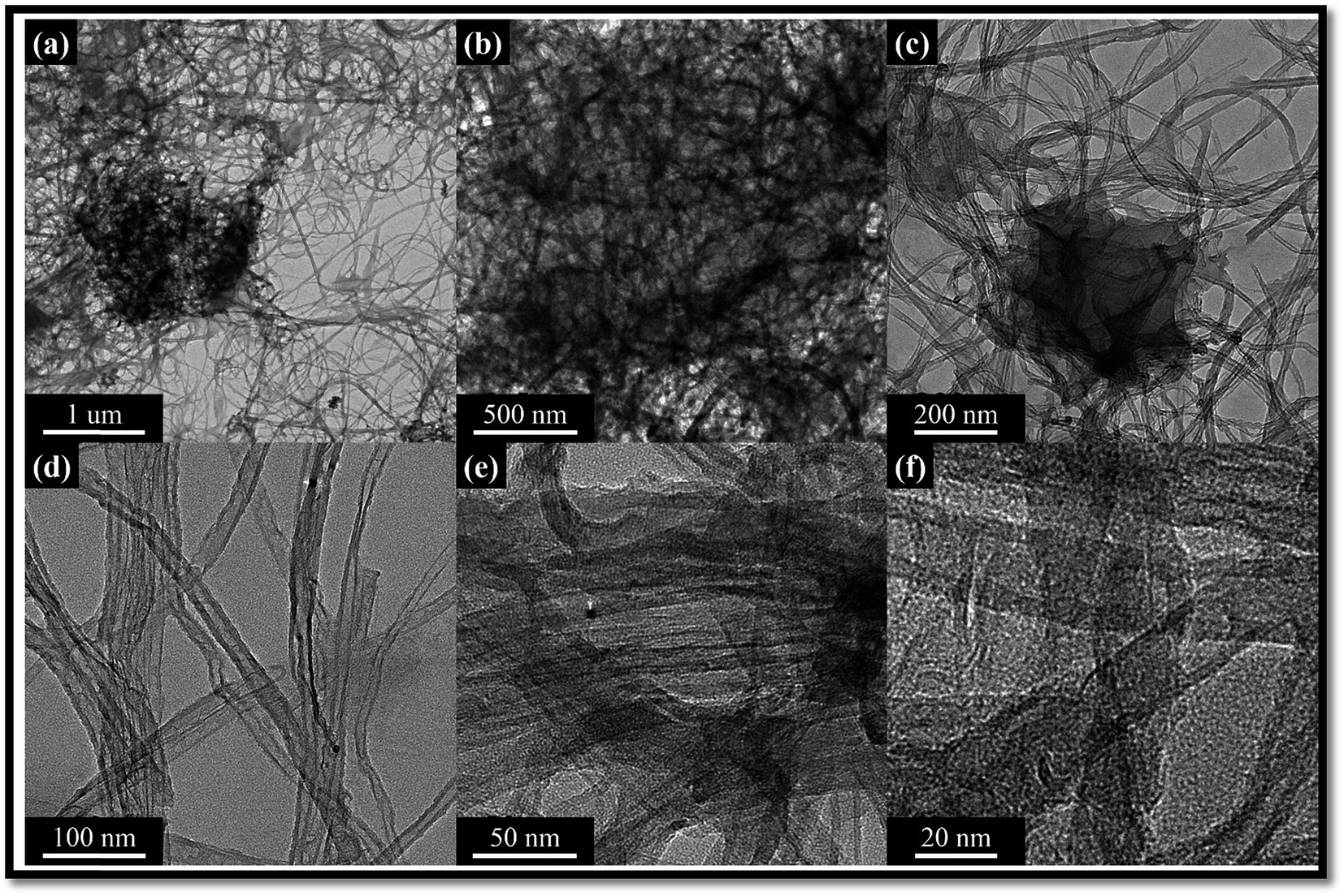 | ||
| Fig. 4 (a) N-MWCNT (b–f) different magnification of N-MWCNT/cellulose hybrid composite. | ||
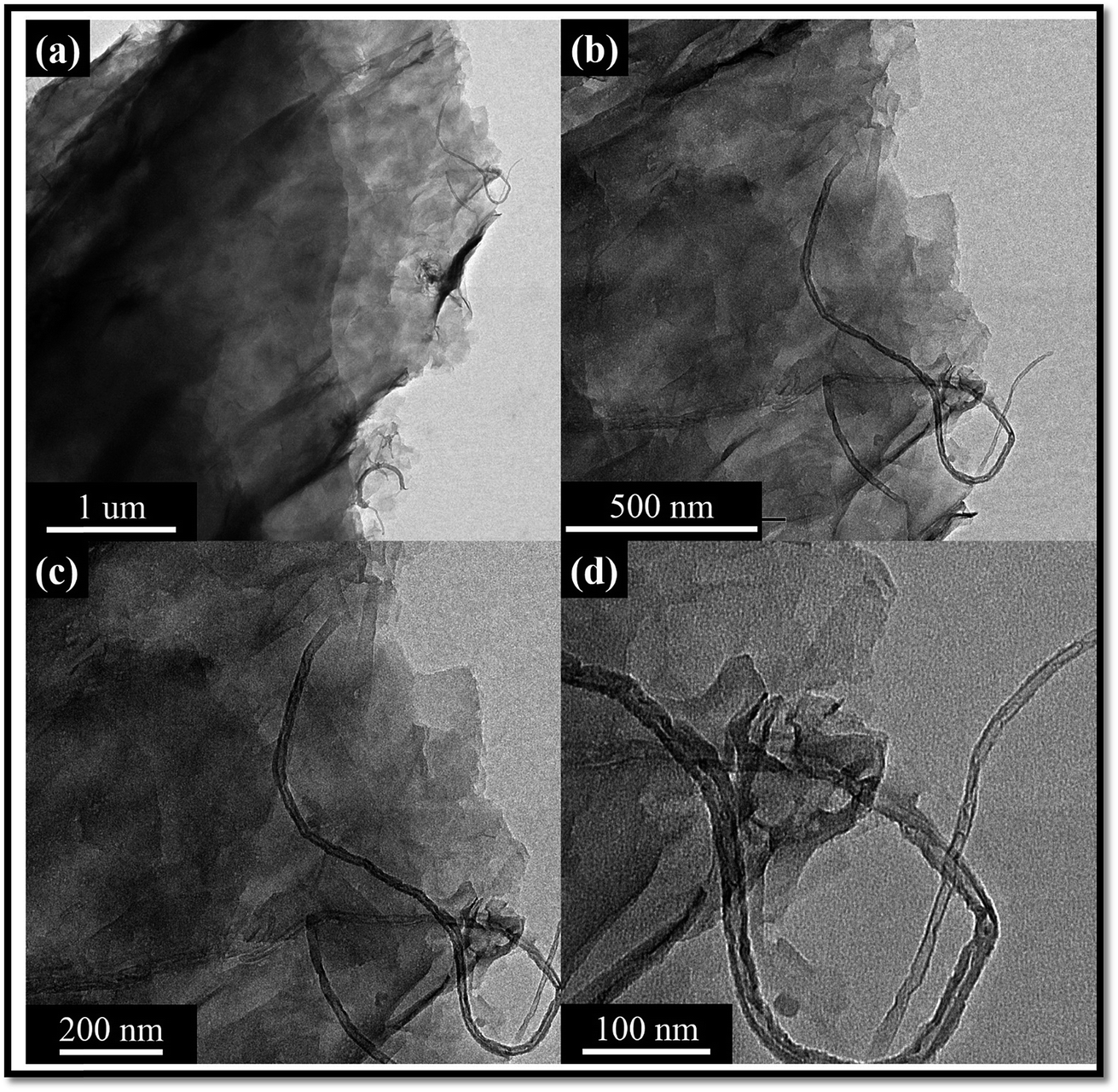 | ||
| Fig. 5 (a) N-MWCNT/GO (b–d) different magnification of N-MWCNT/GO/cellulose hybrid composite. | ||
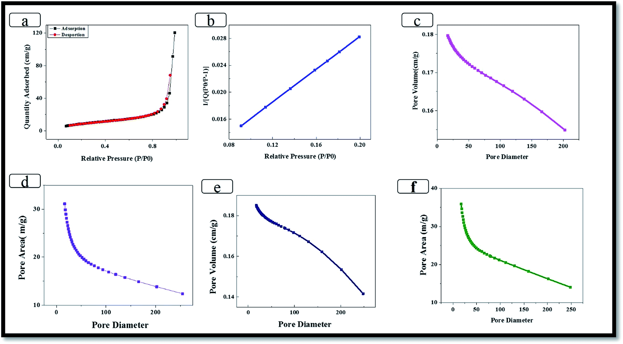 | ||
| Fig. 6 (a–f) BET results of N-MWCNT/GO/cellulose hybrid composite. | ||
3.4. Thermogravimetric analysis (TGA)
The results of the TGA analysis of the hybrid nanocomposites are shown in Fig. 7. The thermal analysis of the hybrid composite samples was carried out under a stream of nitrogen at a heating rate of 10 °C min−1. For the TGA results, temperatures from 10 °C to 1000 °C are used, and the observed weight loss appears in the following three stages. The first weight loss of ∼10 wt% in the temperature range of 25–125 °C is believed associated with the removal of imbibed moisture of cellulose or removal of water molecules (85 °C to 100 °C) released in the hybrid composite. The second dominant weight loss was observed at 275–375 °C, and it was caused by the formation of low molecular weight volatile chemicals owing to the dominant chain scission of the cellulose backbone and the third degradation at 320 °C to 999 °C (N-doped MWCNT/GO). This increase in the degradation behavior due to strong organic/inorganic-phase interaction greatly influences the thermal stability of the hybrid composite. The third step of the thermal-decomposition curve indicates a correspondence with the hybrid composite with the addition of inorganic content. The third degradation shows losses from 320 °C to 999 °C and char residue of 45% at 998.5 °C. | ||
| Fig. 7 Thermal degradation of N-doped MWCNT/GO/cellulose hybrid composite. | ||
3.5. Electrochemical properties
Cyclic voltammograms for MWCNTs, GO and GO–MWCNTs composite electrodes showed a rectangular cyclic voltammogram while a rectangular shape was reported with the GO and GO–MWCNT composite due to the pseudo capacitance behavior originating from oxygen groups on the surface of the GO. No peaks were observed for the MWCNTs electrode as would be expected for carbon material showing a classical double layer capacitor behavior.36–44 However, a broad peak characteristic of carbon material with oxygen groups is observed between 0.4 and 0.5 V for the GO–MWCNT electrode.Cyclic voltammetry analysis (CV) were performed in a potential range between −0.10 and 0.0 V (versus Ag/AgCl) to study the electrochemical properties of the N-MWCNT/GO/cellulose hybrid electrode. Fig. 8a presents the CV curves of the hybrid electrode in 6 M KOH at scan rates of 10, 20, 40, 60, 80 and 100 mV s−1. A pair of well-defined broad redox reaction peaks is visible in the CV curves, indicating that the electrochemical capacitance of the hybrid composite electrode mainly results from the pseudo capacitance. Furthermore, the peak current increases with an increasing scan rate from 10 to 100 mV s−1, which indicates that the good reversibility of fast charge–discharge process. According to the literature,44–49 the surface adsorption properties of alkali ions can decrease the electrolyte starvation near the electrode surface and reduce the internal resistance of the electrode, maybe increasing the pseudocapacitance in the electrochemical reaction.
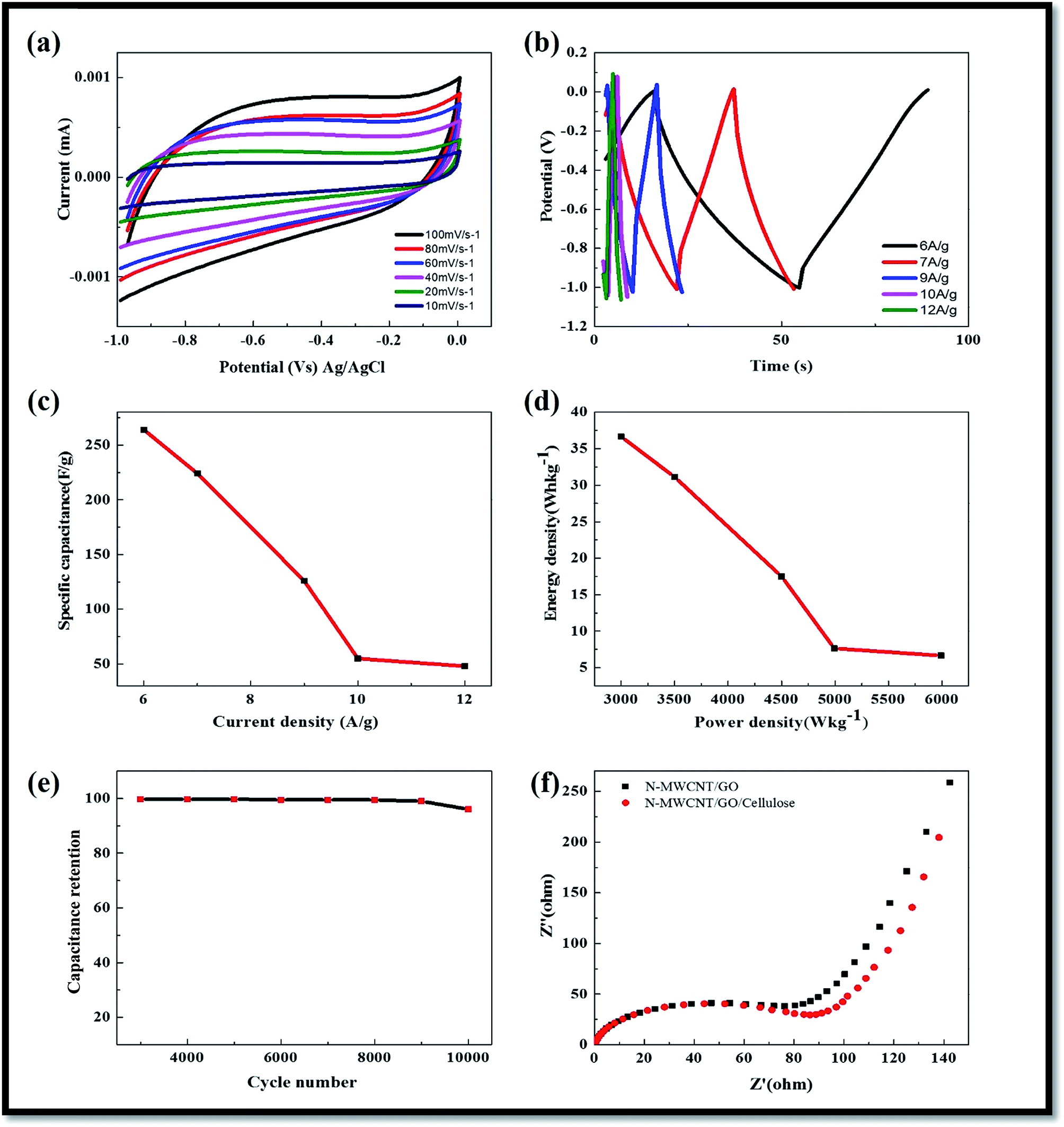 | ||
| Fig. 8 (a) CV of the N-doped MWCNT/GO/cellulose hybrid composite electrodes in 6 M KOH at a scan rates (b) charge–discharge curve of the electrode at various current densities (c) corresponding specific capacitance (d) corresponding power densities (e) capacitance retention (%) (f) Nyquist plots of the hybrid composite electrode. | ||
3.6. Galvanostatic charge–discharge analysis
The calculated specific capacitances for GO–MWCNT, MWCNT and GO were recorded to be ∼190 and 60 F g−1 respectively. These results are consistent with the range of 15 to 80 F g−1 expected for MWCNTs reported in the literature and much higher than the 10.9 F g−1 for GO, possibly due to a much larger size of the GO sheets. The specific capacitances were calculated from the charge–discharge values of 181, 36 and 20 F g−1 for GO–MWCNT, MWCNT and GO respectively. The higher capacitance of the composite can be attributed to an improvement in the conductivity and good dispersion of the MWCNTs in the presence of GO.44–49Fig. 8b shows the five initial galvanostatic charge–discharge curves of the hybrid composite electrode in 6 M KOH solution at a galvanostatic current density of 6, 7, 9, 10 and 12 A g−1. An approximately mirror-like potential–time response can occur, which also implies that the charge–discharge process of the hybrid composite electrodes is reversible. The specific capacitance values were calculated using the following equation.44–46 The specific capacitance of the hybrid composite electrodes showed from the discharge curves to be ca. 264 F g−1 at a current density of 6 A g−1, and these results indicate good capacitance behavior compared to previously-reported cellulose hybrid composite materials.44–46 The good electrochemical capacitance of the synthesized hybrid composite electrode shows a unique morphology and large specific surface area of the materials, which helps enlarge the contact area between the electrodes and electrolytes. Fig. 8c shows the galvanostatic charge–discharge curves of the hybrid composite electrode in 6 M KOH electrolyte at various galvanostatic current densities. The specific capacitances calculated from each discharge curve in Fig. 8c were calculated to be 264, 224, 126, 55, 44 F g−1, corresponding to 6, 7, 9, 10 and 12 A g−1 respectively. At low current densities, the ohmic drop is low and the inner active sites of the hybrid composite electrode can be fully utilized, contributing to achieve the high specific capacitance. Due to the comparatively slow rate of redox reactions at high current densities, the specific capacitance decreases with increasing current density. The small capacitance fading at a very high galvanostatic current density shows that such a novel nanotube structure allows for a rapid redox reaction at high current densities.
Galvanostatic cycling experiments were then undertaken to investigate the cycling stability of the hybrid composite electrode. Charge–discharge studies were performed at a current density of 6 A g−1 in 6 mol L−1 KOH solution and the capacitance retention (%) for 10000 cycles. The electrode exhibited good stability and reversibility with cycling efficiency of 98% after 10000 cycles. Table 1 shows that we also compared our results with the previously-reported N-doped MWCNT/GO/cellulose hybrid composite electrodes.
| Electrode material | Capacitance (F g−1) | Electrolyte | Ref. |
|---|---|---|---|
| Lignin-derived carbon | 102.3, 2 mV s−1 | 6 M KOH | Saha et al. (2014) |
| Cellulose-derived PC | 142.1, 0.5 A g−1 | 6 M KOH | Hao et al. (2014) |
| Carbon nanospheres | 159, 10 mV s−1 | 3 M KOH | Yang et al. (2015) |
| PANI/cellulose film | 160, 0.1 A g−1 | 1 M H2SO4 | Liu et al., 2014 |
| Filterpaper-derived carbon | 115, 5 mV s−1 | 5 M KCl | Jiang et al. (2015) |
| N-Doped-cellulose acetate | 225 F g−1, 0.5 A g−1 | 1 M H2SO4 | Hu et al. (2016) |
| N-Doped-cellulose acetate | 219.8, 2 mV s−1 | 6 M KOH | Hao et al. (2015) |
| Micro and meso porous carbon derived cellulose | 160 F g−1 at 0.2 A g−1 | 1 M Na2SO4 | Xun Tian et al. (2017) |
| Conductive cellulose nanocrystals | 248 F g−1, at 1 A g−1 | 1 M KCl | Xinyun Wu et al. (2014) |
| N-Doped porous carbon | 193 F g−1, at 1 A g−1 | 1 M H2SO4 | Zehong Chena et al. (2017) |
| PPy/cellulose nanocrystal | 240 F g−1, 1 A g−1 | 2 M KCl | Liew et al. 2013 |
| N-Doped-MWCNT/GO/cellulose | 264 F g−1, 6 A g−1 | 6 M KOH | Present study |
3.7. Electrochemical impedance spectroscopy (EIS) analysis
Electrochemical impedance spectroscopy is a powerful technique that gives a wealth of information regarding internal resistance of the electrode material and resistance between the electrode and the electrolyte.We conducted electrochemical impedance measurements from 10 kHz to 100 mHz at a potential of 0.2 V vs. the Ag/AgCl reference electrode (Fig. 8f). Nyquist and Bode plots for the three electrodes were plotted and analyzed. To better understand the processes taking place on the electrode surface, we interpreted these data across two regions, high frequency and low frequency. At a high frequency, the intercept between the impedance plot and the real impedance (Z axis) gives the magnitude of the solution resistance (Rs) of the cell. The solution resistance for the three materials was very low at 0.91, 1.17, and 1.17 U for the MWCNT, GO and GO–MWCNT. Another interesting feature in the high frequency region is the semicircle observed for the MWCNT and GO–MWCNT electrodes.37–49 The phase angle for the impedance plot of the hybrid electrode was observed to be higher than 45° in the low frequencies, suggesting the electrochemical capacitive behavior of the composite materials. The charge transfer resistance (Rct) (from the diameter of the semicircle) of the N-MWCNT and composite electrodes were calculated to be 80 Ω and 90 Ω, respectively, the low Rct value demonstrates the stable electrochemical performance of the composite. It was obvious that the solution resistance and the charge-transfer resistance for hybrid composite suggesting the ESR values in the electrode materials. In the low-frequency region, the linear part called Warburg resistance presents the diffusion behavior of electrolyte ions within the electrodes. Such behavior is caused by the interruptions during the semi-infinite diffusion of ions into the porous structure. The steep slope of Warburg curves indicates fast formation of an electric double-layer. The N-doped carbon based electrode had a more vertical curve than the other electrode, suggesting that the N-functionalized material has a shorter ion diffusion and a better capacitor performance.
4. Conclusions
In summary, a nanostructured morphology of the N-doped MWCNT/GO/cellulose composite was successfully synthesized via a hydrothermal process. The hybrid composite electrodes showed a high specific capacitance (∼264 F g−1 at the current density of 6 A g−1), excellent cycling stability (98%) capacitance retention after 10000 cycles and larger power capability (36.66 kW kg−1). Furthermore, a high specific capacitance was maintained at a high charge/discharge current density due to the unique structure and large surface area of the hybrid composite electrode. The remarkable electrochemical performance was ascribed to the inter-bonded cellulose structure and porous carbon surface. The relatively high surface area, reasonable distribution of pores, good electric conductivity, short ion diffusion path, and fast charge transfer speed within the electrode during charging/discharging also contributed to the high power density.
Conflicts of interest
There are no conflicts to declare.Acknowledgements
This research was supported by the Basic Science Research Program through the National Research Foundation of Korea (NRF-2017R1D1A1B03028368), funded by the Ministry of Education and “Infrastructure Establishment of Thermal Energy Conversion, Desalination using Seawater Thermal Energy (2/3)” funded by the Korea Research Institute of Ships and Ocean Engineering (PES9060) and KEPCO Research Center (KEPRI) (Project: Development of ternary based refrigerant and waste heat recovery ORC cycle) and Institute for Information & communications Technology Promotion (IITP) grant funded by the Korea Government (MSIP) (No. R75201600050001002) and also supported under the frame work of 2017 International and Cooperation Programmed by National Research Foundation of Korea (Grant no. 2017K1A4A3013662).References
- W. Shen, T. Hu and W. Fan, RSC Adv., 2014, 4, 9126–9132 RSC.
- H. P. S. Abdul Khalil, A. H. Bhat and A. F. Ireana Yusra, Carbohydr. Polym., 2012, 87, 963–979 CrossRef CAS.
- L. Deng, R. J. Young, I. A. Kinloch, A. M. Abdelkader, S. M. Homes and D. A. De Haro-Del Rio, et al., ACS Appl. Mater. Interfaces, 2013, 5, 9983–9990 CAS.
- H. D. Huang, C. Y. Liu, L. Q. Zhang, G. J. Zhong and Z. M. Li, ACS Sustainable Chem. Eng., 2015, 3, 317–324 CrossRef CAS.
- D. Klemm, B. Heublein, H. P. Fink and A. Bohn, Angew. Chem., Int. Ed., 2005, 44, 3358–3393 CrossRef CAS PubMed.
- N. Lavoine, I. Desloges, A. Dyfresbe and J. Bras, Carbohydr. Polym., 2012, 90, 735–764 CrossRef CAS PubMed.
- X. Zhang, H. Zhang, C. Li, K. Wang, X. Sun and Y. Ma, RSC Adv., 2014, 4, 45862–45884 RSC.
- K. Subramani, N. Sudhan, R. Divyaa and M. Sathish, RSC Adv., 2017, 7, 6648–6659 RSC.
- D. Saha, Y. Li, Z. Bi, J. Chen, J. K. Keum and D. K. Hensley, et al., Langmuir, 2014, 30, 900–910 CrossRef CAS PubMed.
- B. Chang, Y. Guo, Y. Li, H. Yin, S. Zhang and B. Yang, et al., Journal of Materials Chemistry A, 2015, 3, 9565–9577 RSC.
- P. Hao, Z. Zhao, J. Tian, H. Li, Y. Sang and G. Yu, et al., Nanoscale, 2014, 6, 12120–12129 RSC.
- L. Sun, Y. Fu, C. Tian, Y. Yang, L. Wang and J. Yin, et al., ChemSusChem, 2014, 7, 1637–1646 CrossRef CAS PubMed.
- M. G. Adsul, D. A. Rey and D. V. Gokhale, J. Mater. Chem., 2011, 21, 2054–2056 RSC.
- Q. Zheng, A. Javadi, R. Sabo, Z. Cai and S. Gong, RSC Adv., 2013, 3, 20816–20823 RSC.
- J. Cai and L. Zhang, Macromol. Biosci., 2005, 5, 539–548 CrossRef CAS PubMed.
- J. Cai and L. Zhang, Biomacromolecules, 2006, 7, 183–189 CrossRef CAS PubMed.
- L. Ping and Lo H. You, ACS Appl. Mater. Interfaces, 2010, 2, 2413–2420 Search PubMed.
- Z. Weng, Y. Su, D. W. Wang, F. Li, J. Du and H. M. Cheng, Adv. Energy Mater., 2011, 1, 917–922 CrossRef CAS.
- R. Farma, M. Deraman, A. Awitdrus, I. A. Talib, E. Taer and N. H. Basri, et al., Bioresour. Technol., 2013, 132, 254–261 CrossRef CAS PubMed.
- L. L. Zhang and X. S. Zhao, Chem. Soc. Rev., 2009, 38, 2520–2531 RSC.
- M. Seredych and T. J. Bandosz, J. Mater. Chem. A, 2013, 1, 11717–11727 CAS.
- L. F. Chen, Z. H. Huang, H. W. Liang, W. T. Yao, Z. Y. Yu and S. H. Yu, Energy Environ. Sci., 2013, 6, 3331–3338 CAS.
- H. L. Guo, P. Su, X. Kang and S. K. Ning, J. Mater. Chem. A, 2013, 1, 2248–2255 CAS.
- Y. Wang, Y. Shao, D. W. Matson, J. Li and Y. Lin, ACS Nano, 2010, 4, 1790–1798 CrossRef CAS PubMed.
- G. Rasines, P. Lavela, C. Macías, M. C. Zafra, J. L. Tirado and J. B. Parra, et al., Carbon, 2015, 83, 262–274 CrossRef CAS.
- Z. Qiu, D. He, Y. Wang, X. Zhao, W. Zhao and H. Wu, RSC Adv., 2017, 7, 7843–7856 RSC.
- I. Shakir, Electrochim. Acta, 2014, 129, 396–400 CrossRef CAS.
- Y. K. Kim and D. H. Min, Langmuir, 2009, 25, 11302–11306 CrossRef CAS PubMed.
- Q. Wang, J. Yan, Y. Wang, T. Wei, M. Zhang and X. Jing, et al., Carbon, 2014, 67, 119–127 CrossRef CAS.
- C. K. Kim, In T. Choi, S. H. Kang and H. K. Kim, RSC Adv., 2017, 7, 35565–35574 RSC.
- P. Gómez-Romero, M. Chojak, K. Cuentas-Gallegos, J. A. Asensio, P. J. Kulesza and N. Casan-Pastor, et al., Electrochem. Commun., 2003, 5, 149–153 CrossRef.
- T. Wei, X. Wei, Y. Gao and H. Li, Electrochim. Acta, 2015, 169, 186–194 CrossRef CAS.
- F. Su, C. K. Poh, J. S. Chen, G. Xu, D. Wang and Q. Li, et al., Energy Environ. Sci., 2011, 4, 717–724 CAS.
- L. Zhang, F. Zhang, X. Yang, K. Leng, Y. Huang and Y. Chen, Small, 2013, 9, 1342–13477 CrossRef CAS PubMed.
- Z. Peng, J. Lin, R. Ye, E. L. G. Samuel and M. J. Tour, ACS Appl. Mater. Interfaces, 2015, 7, 3414–3419 CAS.
- Y. Zhu, S. Murali, W. Cai, X. Li, J. W. Suk and J. R. Potts, et al., Adv. Mater., 2010, 22, 3906–3924 CrossRef CAS PubMed.
- H. X. Kong, Curr. Opin. Solid State Mater. Sci., 2013, 17, 31–37 CrossRef CAS.
- B. Xu, S. Hou, G. Cao, F. Wu and Y. Yang, J. Mater. Chem., 2012, 22, 19088 RSC.
- T. Wei, X. Wei, Y. Gao and H. Li, Electrochim. Acta, 2015, 169, 186–194 CrossRef CAS.
- D. S. Su and R. Schlogl, ChemSusChem, 2010, 3, 136–168 CrossRef CAS PubMed.
- H. M. Jeong, et al., Nano Lett., 2011, 11, 2472–2477 CrossRef CAS PubMed.
- Y. Zhao, et al., Angew. Chem., Int. Ed., 2012, 51, 11371–11375 CrossRef CAS PubMed.
- Z. Wen, et al., Adv. Mater., 2012, 24, 5610–5616 CrossRef CAS PubMed.
- Z. Y. Wu, H. W. Liang, C. Li, B. C. Hu, X. X. Xu and Q. Wang, et al., Nano Res., 2014, 7, 1861–1872 CrossRef CAS.
- J. P. Paraknowitsch and A. Thomas, Energy Environ. Sci., 2013, 6, 2839–2855 CAS.
- U. N. Maiti, J. Lim, K. E. Lee, W. J. Lee and S. O. Kim, Adv. Mater., 2014, 26, 615–619 CrossRef CAS PubMed.
- H. Wang, T. Maiyalagan and X. Wang, ACS Catal., 2012, 2, 781–894 CrossRef CAS.
- Y. Huang, J. Liang and Y. Chen, Small, 2012, 8, 1805–1834 CrossRef CAS PubMed.
- S. Biswas and L. T. Drzal, ACS Appl. Mater. Interfaces, 2010, 2, 2293–2300 CAS.
| This journal is © The Royal Society of Chemistry 2017 |