 Open Access Article
Creative Commons Attribution 3.0 Unported Licence
High mechanical properties of epoxy networks with dangling chains and tunable microphase separation structure
Yizhou Huang ,
Yazhou Tian,
Yuanyuan Li
 ,
Xiaocun Tan,
Qing Li,
Jue Cheng* and
Junying Zhang*
The Key Laboratory of Beijing City on Preparation and Processing of Novel Polymer Materials, Beijing University of Chemical Technology, Beijing 100029, China. Fax: +86 10 6442 5439; Tel: +86 10 6442 5439E-mail: chengjue@mail.buct.edu.cn; zhangjy@mail.buct.edu.cn
First published on 20th October 2017
Abstract
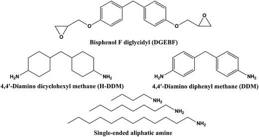
A series of epoxy systems with tunable rigid-flexibility were prepared by the curing reaction of bisphenol F diglycidyl (DGEBF), a single-ended amine with alkyl chains (n-butyl, octyl, dodecyl), 4,4′-diaminodiphenylmethane (DDM) and 4,4′-diaminodicyclohexylmethane (H-DDM). By means of adjusting the composition of the curing agent (the molar ratio between H-DDM and DDM), nano- and submicron-sized phase separations were observed by atomic force microscopy (AFM). And diffraction peaks were not observed in the wide angle X-ray scattering (WAXS) characterization which revealed that there was no crystallization in the modified epoxy resin. Besides, the result of nanoIR characterization proved that the aggregation of aliphatic chains led to the microphase separation structure, which can remarkably improve the mechanical properties of epoxy resins. The effects of side chains on the mechanical and thermal properties of epoxy networks were investigated. Especially, the EC8-5′ (the molar ratio between H-DDM and DDM was 45/55, the mass ratio of the n-octyl amine to DGEBF was 5![[thin space (1/6-em)]](https://www.rsc.org/images/entities/char_2009.gif) :
:![[thin space (1/6-em)]](https://www.rsc.org/images/entities/char_2009.gif) 100) sample exhibited splendid mechanical properties with an attractive tensile strength of 88.4 MPa, an elongation at break of 6.6% and a tensile modulus of 3.5 GPa.
100) sample exhibited splendid mechanical properties with an attractive tensile strength of 88.4 MPa, an elongation at break of 6.6% and a tensile modulus of 3.5 GPa.
1 Introduction
Epoxy resins are used extensively as coatings, adhesives, and structural composite materials due to their excellent engineering properties.1 However, the inherently highly cross-linked molecular structures also give shortcomings, such as poor resistance to fracture and low fracture toughness.2 Consequently, an enormous amount of research effort goes into toughening epoxy polymers. Traditional toughening methods include the incorporation of soft materials such as rubber particles,3,4 core/shell particles,5,6 block copolymers (BCPs),7–9 et al. However, soft segments can significantly improve toughness with a sharp reduction of strength, modulus and glass transition temperature (Tg). It has also been demonstrated that toughness can be greatly improved by using rigid nanoparticles such as carbon nanotubes,10–12 silica,13–15 titania,16,17 alumina18,19 and POSS.20 Meanwhile, the presence of such fillers can increase modulus without sacrificing Tg. However, it leads to agglomeration and reduces the processability of a material. Recently, studies have focused on novel approaches to toughen epoxy thermosets. For instance, interpenetrating networks21,22 and hyperbranched polymer23,24 can not only toughen epoxy resin but also improve modulus without sacrificing Tg which has attracted the attention of researchers. However, prohibitive costs and complicated preparation limit the applications of these strategies.Tao Yang et al.25 discovered that the side aliphatic chains would facilitate the self-assemble into bump structures, which were proved to toughen the epoxy resins. Longhan Ba et al.26 had discussed the mechanical properties and toughening mechanisms of the diglycidyl ether of bisphenol F (DGEBF) modified by partly reacting with monofunctional epoxy. Effect of different length and content of side chains on mechanical properties has been discussed.26 The major corresponding toughening mechanism of bump structure in the modified epoxies was attributed to the combination of shear yielding and bridging constraint effect.25,26 It was speculated that the appearance of microphase separation was the result of the incompatibility between the flexible side chains and rigid backbone of benzene ring. However, there are few studies on the effect of curing agent structure on the microphase separation behaviors.
Comprehensive understanding of the formation process of microphase separation structure is required by efficient design of ameliorated materials. Only in this way, their structures can be optimized and the inherent defects can either be eliminated or reduced. In this work, the influence of curing agent structure, the length and content of flexible side chain on morphology and mechanical properties were systematically studied. The appearance of microphase separation was achieved by adjusting the compatibility of the main chains and the side chains and the rigidity of crosslinking networks which was accomplished by tuning the molar ratio of 4,4′-diaminodiphenylmethane (DDM) and 4,4′-diaminodicyclohexylmethane (H-DDM) in the curing agent. Meanwhile, three kinds of the single-ended amine with alkyl chains (n-butyl, octyl, dodecyl) were introduced in the cured epoxy networks and the effect of the length and content of the alkyl chains on the morphology was investigated. The variation tendency of microphase separation was examined by atomic force microscopy (AFM). The internal components of bump structures were studied by nanoIR, which allows nanoscale measurements of infrared absorption as a function of the wavenumber to characterize specimens at spatial resolutions not achievable previously.27,28 The formation mechanism of the microphase separation was expatiated. Moreover, tensile tests, impact tests and dynamic mechanical analysis (DMA) results were carried out for the investigation of the mechanical and thermal mechanical properties.
2 Experimental section
2.1. Materials
DGEBF (trade name Epon170, equivalent epoxy weight 165.3 g mol−1) was bought from Epoxy Division of China Petrochemical Group Baling Petrochemical Co., Ltd. Single-ended aliphatic amine (n-butylamine, n-octylamine, n-dodecylamine), DDM (98%+) and H-DDM (98%+) were purchased from Aladdin Industrial Corporation. The molecular structures of these materials are shown in Fig. 1.2.2. Preparation of modified epoxy resin networks with side aliphatic chains induced by single-ended aliphatic amine
DGEBF were mixed with DDM according to the stoichiometric ratio, and then single-ended aliphatic amine was loaded (mass ratio of the aliphatic amine between epoxy group of DGEBF was 2.5![[thin space (1/6-em)]](https://www.rsc.org/images/entities/char_2009.gif) :
:![[thin space (1/6-em)]](https://www.rsc.org/images/entities/char_2009.gif) 100 and 5
100 and 5![[thin space (1/6-em)]](https://www.rsc.org/images/entities/char_2009.gif) :
:![[thin space (1/6-em)]](https://www.rsc.org/images/entities/char_2009.gif) 100). Subsequently, the blends were stirred homogeneously for 10 min. After the pre-cured process under 60 °C for 2 h, the reaction mixture was cured under 100 °C for another 2 h, 130 °C for 2 h and 150 °C for 4 h. The cured samples were named as EC4, EC8 and EC12 according to the carbon number in the alkyl chains of the amine, and the pure E0 system (mass ratio of amine and DGEBF is 0/100) was called the blank sample.
100). Subsequently, the blends were stirred homogeneously for 10 min. After the pre-cured process under 60 °C for 2 h, the reaction mixture was cured under 100 °C for another 2 h, 130 °C for 2 h and 150 °C for 4 h. The cured samples were named as EC4, EC8 and EC12 according to the carbon number in the alkyl chains of the amine, and the pure E0 system (mass ratio of amine and DGEBF is 0/100) was called the blank sample.
Then, DGEBF were well mixed with DDM and H-DDM according to the stoichiometric ratio and the n-octylamine was loaded (mass ratio of the n-octylamine between DGEBF was 5![[thin space (1/6-em)]](https://www.rsc.org/images/entities/char_2009.gif) :
:![[thin space (1/6-em)]](https://www.rsc.org/images/entities/char_2009.gif) 100). For example, the EC8-5 cured by DDM and H-DDM (the molar ratio between H-DDM and DDM was 20/80) instead of pure DDM was named as EH-20.
100). For example, the EC8-5 cured by DDM and H-DDM (the molar ratio between H-DDM and DDM was 20/80) instead of pure DDM was named as EH-20.
Last, DGEBF were mixed with DDM and H-DDM according to the stoichiometric ratio (the molar ratio between H-DDM and DDM was 45/55) and then single-ended aliphatic amine was added (mass ratio of the aliphatic amine between epoxy group of DGEBF was 2.5![[thin space (1/6-em)]](https://www.rsc.org/images/entities/char_2009.gif) :
:![[thin space (1/6-em)]](https://www.rsc.org/images/entities/char_2009.gif) 100 and 5
100 and 5![[thin space (1/6-em)]](https://www.rsc.org/images/entities/char_2009.gif) :
:![[thin space (1/6-em)]](https://www.rsc.org/images/entities/char_2009.gif) 100). For example, EC4-5 cured by H-DDM/DDM instead of DDM was named as EC4-5′. The detailed formulations of all the samples were listed in Tables 1, 2 and 3.
100). For example, EC4-5 cured by H-DDM/DDM instead of DDM was named as EC4-5′. The detailed formulations of all the samples were listed in Tables 1, 2 and 3.
| Sample | EC4-2.5 | EC4-5 | EC8-2.5 | EC8-5 | EC12-2.5 | EC12-5 |
|---|---|---|---|---|---|---|
| n-Butylamine | 2.5 | 5 | — | — | — | — |
| n-Octylamine | — | — | 2.5 | 5 | — | — |
| n-Dodecylamine | — | — | — | — | 2.5 | 5 |
| DGEBF | 100 | 100 | 100 | 100 | 100 | 100 |
| DDM | 26.2 | 22.8 | 27.7 | 25.8 | 28.3 | 26.9 |
| Sample | EH-20 | EH-25 | EH-30 | EH-35 | EH-40 | EH-45 | EH-50 | EH-55 | EH-60 |
|---|---|---|---|---|---|---|---|---|---|
| n-Octylamine | 5 | 5 | 5 | 5 | 5 | 5 | 5 | 5 | 5 |
| DGEBF | 100 | 100 | 100 | 100 | 100 | 100 | 100 | 100 | 100 |
| DDM | 20.6 | 19.3 | 18.1 | 16.7 | 15.5 | 14.2 | 12.9 | 11.6 | 10.3 |
| H-DDM | 5.5 | 6.8 | 8.2 | 9.6 | 10.9 | 12.3 | 13.7 | 15.1 | 16.4 |
| Sample | E0′ | EC4-2.5′ | EC4-5′ | EC8-2.5′ | EC8-5′ | EC12-2.5′ | EC12-5′ |
|---|---|---|---|---|---|---|---|
| n-Butylamine | — | 2.5 | 5 | — | — | — | — |
| n-Octylamine | — | — | — | 2.5 | 5 | — | — |
| n-Dodecylamine | — | — | — | — | — | 2.5 | 5 |
| DGEBF | 100 | 100 | 100 | 100 | 100 | 100 | 100 |
| DDM | 16.3 | 14.4 | 12.6 | 15.2 | 14.2 | 15.6 | 14.8 |
| H-DDM | 14.2 | 12.5 | 10.9 | 13.2 | 12.3 | 13.5 | 12.9 |
2.3. Characterization techniques
![[thin space (1/6-em)]](https://www.rsc.org/images/entities/char_2009.gif) δ curves were plotted as a function of temperature. Specimen dimensions were 20 mm × 6 mm × 0.6 mm.
δ curves were plotted as a function of temperature. Specimen dimensions were 20 mm × 6 mm × 0.6 mm.3 Results and discussion
3.1. Morphological behavior
Fig. 2 shows the phase images of EC4, EC8 and EC12. This results suggested that microphase separation was absent in DGEBF/DDM/single-ended aliphatic amine system. This phenomenon was different from the reports in the literature.25,26 Previous studies showed that bringing aliphatic pendant chains into epoxy matrix which was DGEBF cured by hexahydrophthalic anhydride (HHPA) would lead to microphase separation. Due to the structural and compatibility differences between aliphatic chain and backbone of epoxy resin which contains benzene ring, the flexible side chain self-assembly formed microphase separation in cured epoxy resin.25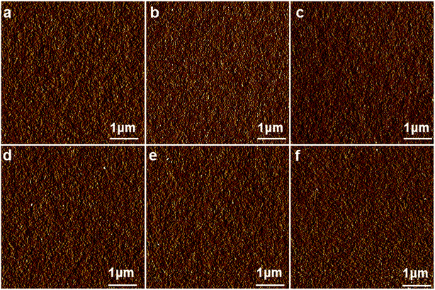 | ||
| Fig. 2 AFM phase images of EC4-2.5 (a), EC8-2.5 (b), EC12-2.5 (c), EC4-5 (d), EC8-5 (e) and EC12-5 (f). The morphology of them was homogeneous and featureless. | ||
However, there was no microphase separation observed by AFM when DDM instead of HHPA as the curing agent. It was speculated that the absence of microphase separation was due to the excess of regular benzene ring structures, which made the main chain particularly rigid. Furthermore, rigid main chain structure limited the movement of side chain prevented the self-assemble. It was speculated that the presence of microphase separation was not only related to the compatibility between the side chain and the main chain, but also limited by the rigidity of the backbone.
The composition of the curing agent was changed by tuning the molar ratio of H-DDM/DDM to adjust the rigid of the backbone (Table 2). Fig. 3 shows the phase images of DGEBF/DDM/H-DDM/n-octylamine systems. For the EH-20 system, uniformly distributed tiny phases were observed. For the EH-25 system, similar and more pronounced phases were presented. When the ratio was 30/70, clearly dispersed phases were observed, and more regular microphases appeared with the increasing of H-DDM content. When ratio exceeded 55/45, there was little phase separation. With the continuous reduction of the benzene ring, the compatibility between flexible side chain and backbone was getting better and better. However, good compatibility can't form phase separation. The results of phase images in Fig. 3 indicated that the rigidity of backbone played an important role in the formation of microphase separation. On the one hand, the rigidity of the main chain was deemed to the major factor affecting microphase separation when the content of H-DDM was relatively low. High rigidity of the main chain limited the chemical rotation of bonds making the side chains difficult to self-assemble. On the other hand, when the H-DDM content was relatively high, the rigidity of the backbone limited the aggregation of side chains. At this moment, the compatibility between flexible side chain and backbone became the principal factor.
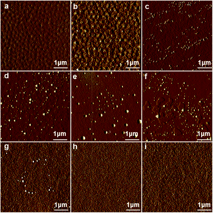 | ||
| Fig. 3 AFM phase images of EH-20 (a), EH-25 (b), EH-30 (c), EH-35 (d), EH-40 (e), EH-45 (f), EH-50 (g), EH-55 (h), EH-60 (i). | ||
The uniformly distributed spherical bump structures were observed in (Fig. 3d–f) EH-35, EH-40 and EH-45 system, and the better distribution of submicro- and nano-structures were observed in the EH-45 system. It was noted that the co-existence of submicro- and nano-sized bump structures had significant effect on the toughness of epoxy resins and improved the mechanical properties dramatically.25 Therefore, the following studies are carried out under this proportion (molar ratio of H-DDM and DDM was 45/55) of the curing agent.
The DGEBF/DDM/H-DDM/single-ended aliphatic amine systems (Table 3) showed completely different morphologies from DGEBF/DDM/single-ended aliphatic amine systems (Table 1) in Fig. 4. After adjusting the composition of curing agent, all modified samples clearly showed different shapes and sizes of dispersed phases. When epoxy contained 2.5 phr of side chains, sparse phase separation structures are shown in EC4-2.5, EC8-2.5, EC12-2.5 (Fig. 4a–c). When epoxy contained 5 phr of side chains, the intensity of the dispersed bump structure increased (Fig. 4d–f). Moreover, regular spherical structures were observed in EC8-5, EC12-5 (Fig. 4e and f). It was postulated that the difference in length of side aliphatic chains led to the size variation of the bump structure as well. For the EC8 system, massive nano-sized (30–50 nm) and submicron-sized (135–270 nm) found in EC8-5 (Fig. 4e). Besides, nano-sized (70–88 nm) and submicron-sized (360–420 nm) dispersed phases coexisted in EC12-5 (Fig. 4f). The phenomenon suggested that the longer length of side chains, the larger scale phase separations.
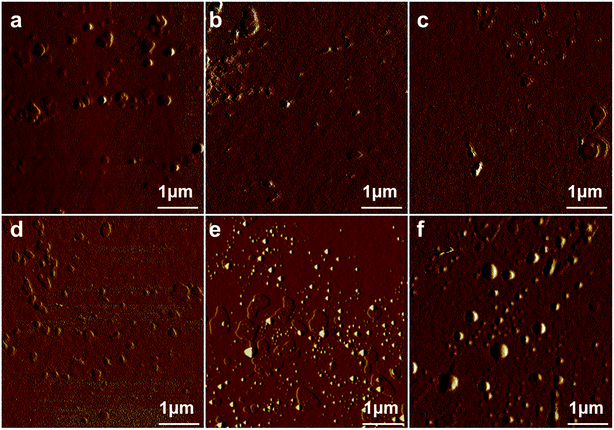 | ||
| Fig. 4 AFM phase images of EC4-2.5′ (a), EC8-2.5′ (b), EC12-2.5′ (c), EC4-5′ (d), EC8-5′ (e) and EC12-5′ (f). | ||
It was noteworthy that uniformly distributed spherical submicro- and nano-structures were observed in EC8-5′ and EC12-5′ systems. According to previous studies,25 similarly bump structure formed by self-assembly of side chains can dramatically improve mechanical properties. Consequently, the research emphases were put on the 5 phr of side chain systems which were expected to have splendid mechanical properties.
3.2. WAXS characterization
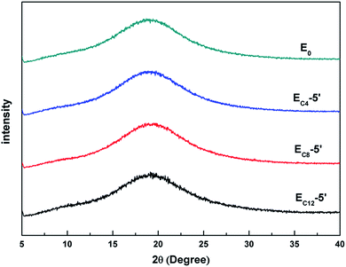
WAXS curves of E0, EC4-5′, EC8-5′ and EC12-5′ were showed in Fig. 5. The curve of E0 represented amorphous polymer.29 Besides, diffraction peaks were not found in EC4-5′, EC8-5′ and EC12-5′, which showed relatively more microphase separation. This results suggested that these bump structures were not composed of crystalline structures which was similar to that of polyethylene.303.3. NanoIR characterization
The characterization technique, nanoIR, was carried out in order to investigate the real structure of microphase separation. The nanoIR is a probe-based measurement tool that reveals the chemical composition of samples at the nanoscale.31 Fig. 6 showed an AFM topographic image with lighter areas representing higher elevations of EC8-5′ sample surface. The correspondingly colored plus signed in the middle panels identify the locations where the spectra at the bottom were collected. Representative spectra of A (red) and B (blue) were shown at the bottom of Fig. 6. The stretch peak at 1608 cm−1 represented the benzene rings, and stretch around at 2930 and 2860 cm−1 stand for the methylene C–H. It was observed that the intensity of the benzene ring stretch peak remains constant for two positions. It could be seen that the intensities at A were higher than B. It demonstrated that the methylene content of bump structure was higher than homogeneous structure. It indicated that the aggregation of aliphatic chain led to the microphase separation structure in this system.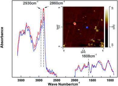 | ||
| Fig. 6 Local microdomains of EC8-5′. Contact mode AFM height image (top A-red, B-blue) and IR spectra at selected positions (bottom). | ||
3.4. Mechanical properties
Tensile tests and impact tests of EH and E′ systems were performed in order to verify the effect of the microphase separation on mechanical properties. The results were given in Tables 4 and 5. For the EH system, the strength and modulus increased with the raise of the content of H-DDM in a certain range (molar ratio of H-DDM/DDM from 20/80 to 45–55). When the ratio got to 45/55, the tensile strength and tensile modulus got to the maximum values (88.4 MPa and 3.5 GPa), which were consistent with our previous expectation that submicro- and nano-structures would improve mechanical properties dramatically. When the molar ratio of H-DDM exceeded 45/55, strength and modulus decreased. On the one hand, the increase of H-DDM content resulted in the decrease of rigidity of the whole network, which weakened the strength. On the other hand, adjusting the content of H-DDM affected the formation of microphase separation structure (Fig. 3). Therefore, little change in strength was owing to the interaction of these two results. However, tensile modulus varied apparently with the adjusting curing agent. As shown in AFM phase images (Fig. 3), the variation trend of the modulus coincided with the variation trend of morphologies. It was demonstrated that uniformly distributed spherical microphase separation had a profound effect on the improvement of tensile modulus. Based on the morphology characterizations by AFM, the verification of microphase separation structure by nanoIR and mechanical properties, it was tentatively interpreted the increasing of modulus to the decrease of free volume. Under the influence of aggregations of aliphatic chains, the main chains got closer. Namely, the crosslinking networks piled up more tightly, which decreased the free volume. According to the reports in the literature, the decrease of free volume led to the increasing of modulus.32| Cured samples | EH-20 | EH-25 | EH-30 | EH-35 | EH-40 | EH-45 | EH-50 | EH-55 | EH-60 |
|---|---|---|---|---|---|---|---|---|---|
| Tensile strength (MPa) | 84.1 ± 1.7 | 85.8 ± 1.4 | 85.3 ± 0.8 | 85.5 ± 1.1 | 88.2 ± 0.9 | 88.4 ± 0.6 | 85.1 ± 1.1 | 84.5 ± 1.4 | 82.4 ± 1.3 |
| Elongation (%) | 5.6 ± 0.6 | 6.1 ± 0.4 | 5.6 ± 0.6 | 6.7 ± 0.5 | 6.1 ± 0.6 | 6.6 ± 0.8 | 6.7 ± 0.6 | 6.2 ± 0.7 | 5.5 ± 0.9 |
| Modulus (GPa) | 3.0 ± 0.1 | 3.1 ± 0.1 | 3.2 ± 0.1 | 3.3 ± 0.1 | 3.3 ± 0.1 | 3.5 ± 0.1 | 3.3 ± 0.1 | 3.2 ± 0.1 | 3.2 ± 0.1 |
| Impact strength (kJ m−2) | 21.2 ± 0.2 | 22.2 ± 1.3 | 21.3 ± 0.3 | 20.5 ± 0.7 | 20.7 ± 0.5 | 21.1 ± 0.4 | 23.0 ± 0.4 | 21.2 ± 0.5 | 19.9 ± 0.7 |
| Cured sample | E0′ | EC4-2.5′ | EC4-5′ | EC8-2.5′ | EC8-5′ | EC12-2.5′ | EC12-5′ |
|---|---|---|---|---|---|---|---|
| Tensile strength (MPa) | 76.1 ± 1.4 | 86.4 ± 1.6 | 85.84 ± 1.8 | 84.8 ± 1.9 | 88.4 ± 0.6 | 85.9 ± 0.6 | 86.1 ± 1.3 |
| Elongation (%) | 4.6 ± 0.9 | 6.1 ± 0.9 | 6.0 ± 0.9 | 6.2 ± 0.8 | 6.6 ± 0.8 | 6.1 ± 0.8 | 6.7 ± 0.9 |
| Modulus (GPa) | 2.7 ± 0.1 | 3.0 ± 0.1 | 3.0 ± 0.1 | 3.1 ± 0.1 | 3.5 ± 0.1 | 3.3 ± 0.1 | 3.3 ± 0.1 |
| Impact strength (kJ m−2) | 18.3 ± 0.4 | 24.1 ± 1.1 | 23.1 ± 0.7 | 20.5 ± 0.6 | 21.1 ± 0.4 | 19.8 ± 0.7 | 19.9 ± 0.5 |
The results of tensile test and impact test of cured EC4′, EC8′, EC12′ were listed in Table 5. A significant increase of mechanical properties was observed after introducing the microphase separation structure. It was proved that all the nano-, submicro-sized bump structures had a significant effect on the toughness of epoxy resins and enhanced the modulus dramatically. Adjusting the content and length of the aliphatic side chains was able to maximize the tensile strength, the tensile elongation at break and the tensile modulus (88.4 MPa, 6.6% and 3.5 GPa for the EC8-5′ sample). For the different length of side chain, strength did not change significantly. For EC8′ and EC12′ system, strength and elongation at break increased with the raising of the content of side chain.
3.5. DMA and DSC
The thermal mechanical properties of the epoxy resins were investigated by DMA and the results were shown in Fig. 7–9. Little differences of the storage modulus were observed between these EH systems in glassy region or rubbery region because of the similar main structures in the crosslinking networks. The cross-linking density (νe) can be able to be calculated from storage modulus in rubbery region according to the kinetic theory of rubber elasticity using the following equation33| E′ = 3νeRT |
![[thin space (1/6-em)]](https://www.rsc.org/images/entities/char_2009.gif) δ) curve and the values were listed in Table 6. The Tg of cured EH system decreased slightly with the increase of content of H-DDM. Besides, all of the cured epoxy systems had similar sharp single tan
δ) curve and the values were listed in Table 6. The Tg of cured EH system decreased slightly with the increase of content of H-DDM. Besides, all of the cured epoxy systems had similar sharp single tan![[thin space (1/6-em)]](https://www.rsc.org/images/entities/char_2009.gif) δ peaks. It may signify that these systems were pure and homogeneous (Fig. 7b and 9).34
δ peaks. It may signify that these systems were pure and homogeneous (Fig. 7b and 9).34
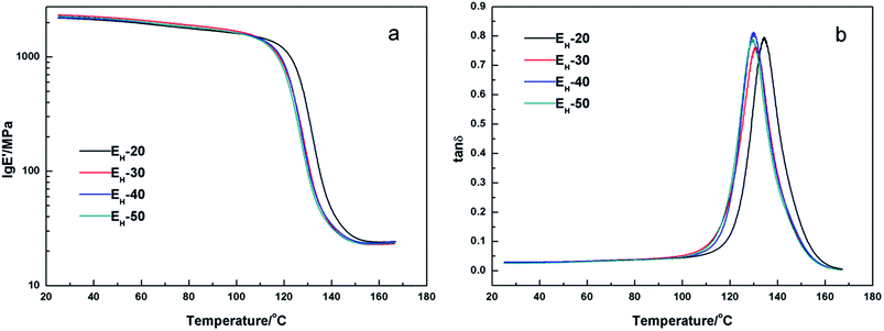 | ||
| Fig. 7 Plots of storage modulus (a) and loss tangent (b) versus temperature of cured EH-20, EH-30, EH-40, and EH-50 systems. | ||
| Cured sample | E0′ | EH-20 | EH-30 | EH-40 | EH-50 | EC4-2.5′ | EC4-5′ | EC8-2.5′ | EC8-5′ | EC12-2.5′ | EC12-5′ |
|---|---|---|---|---|---|---|---|---|---|---|---|
| Tg (°C) | 148.2 | 134.5 | 130.9 | 130.0 | 129.6 | 134.9 | 125.9 | 139.2 | 129.7 | 141.2 | 132.6 |
| νe (mol m−3) | 2563 | 2293 | 2117 | 2185 | 2152 | 1886 | 1753 | 2383 | 2173 | 2082 | 2020 |
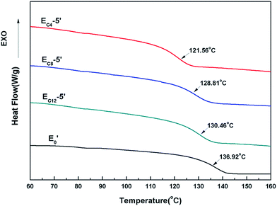
The DMA results of E′ systems were showed in Fig. 8, 9 and Table 6. It was noted that the storage modulus of these systems in glassy region show little difference while the storage modulus in rubbery region decline slightly with increasing of content of single-ended amine. The Tg of cured E′ system decreased sharply with the increasing of content of side chains. The loading of single-ended aliphatic amine reduced the dosage of curing agent so that the rigidity of the whole crosslinking networks was reduced, which led to the decrease of Tg.35 Furthermore, with the increasing of the length of the side chain, the effect of Tg was lower.
The thermal properties of E0′, EC4-5′, EC8-5′ and EC12-5′ were further investigated by the DSC. The variation tendency of TgDSC was similar with TgDMA. Longer length of the side chain, less effect of Tg. This was due to the increasing molecular weight of single-ended aliphatic amine. The molar value of the same mass decreased with increasing of the chain length. Besides, no exothermic peaks were found in the process of elimination of heat history. It was demonstrated that the curing reaction was completed (Fig. 10).
4 Conclusion
A series of epoxy systems with tunable rigid-flexibility containing side aliphatic dangling chains (DGEBF/DDM/H-DDM/n-octylamine system) and a series of epoxy systems with different length of side chains (DGEBF/DDM/H-DDM/single-ended aliphatic amine system) were designed and prepared. The nano- and submicron-sized phase separations were observed by AFM. It was speculated that the participation of side chains into the epoxy network, the compatibility between the side chain and the main chain and the rigidity of the backbone both influenced the microphase separation. Diffraction peaks were not observed in the wide angle X-ray scattering (WAXS) characterization which revealed that there was no crystallization in the modified epoxy resin. Besides, nanoIR characterization proved that the aggregation of aliphatic chains led to the microphase separation structure, which could remarkably improve the mechanical properties of cured epoxy resins. Especially, the EC8-5′ sample exhibited splendid mechanical properties with an attractive tensile strength of 88.4 MPa, an elongation at break of 6.6% and a tensile modulus of 3.5 GPa.Conflicts of interest
There are no conflicts to declare.Acknowledgements
The authors gratefully acknowledge the financial support from the National Key Research Program of China under Grant No. 2016YFB0302000.References
- E. M. Petrie, Epoxy Adhesive Formulations, McGraw Hill Professional, New York, 2005 Search PubMed.
- T. Vidil, F. Tournilhac, S. Musso, A. Robisson and L. Leibler, Prog. Polym. Sci., 2016, 62, 126–179 CrossRef CAS.
- N. T. Kamar and L. T. Drzal, Polymer, 2016, 92, 114–124 CrossRef CAS.
- H. Zhou and S. Xu, Mater. Lett., 2014, 121, 238–240 CrossRef CAS.
- D. Quan and A. Ivankovic, Polymer, 2015, 66, 16–28 CrossRef CAS.
- W. Thitsartarn, X. Fan, Y. Sun, J. C. C. Yeo, D. Yuan and C. He, Compos. Sci. Technol., 2015, 118, 63–71 CrossRef CAS.
- C. Declet-Perez, L. F. Francis and F. S. Bates, Macromolecules, 2015, 48, 3672–3684 CrossRef CAS.
- J. Liu, Z. J. Thompson, H.-J. Sue, F. S. Bates, M. A. Hillmyer, M. Dettloff, G. Jacob, N. Verghese and H. Pham, Macromolecules, 2010, 43, 7238–7243 CrossRef CAS.
- V. Rebizant, A. Venet, F. Tournilhac, E. Girardreydet, C. Navarro, A. Jeanpierre Pascault and L. Leibler, Macromolecules, 2004, 37, 8017–8027 CrossRef CAS.
- F. H. Gojny, M. H. G. Wichmann, U. Köpke, B. Fiedler and K. Schulte, Compos. Sci. Technol., 2004, 64, 2363–2371 CrossRef CAS.
- P. Guo, X. Chen, X. Gao, H. Song and H. Shen, Compos. Sci. Technol., 2007, 67, 3331–3337 CrossRef CAS.
- L. S. Schadler, S. C. Giannaris and P. M. Ajayan, Appl. Phys. Lett., 1998, 73, 3842–3844 CrossRef CAS.
- Y. Poonpipat, K. Leelachai, R. A. Pearson and P. Dittanet, J. Reinf. Plast. Compos., 2017, 36, 1156–1167 CrossRef.
- P. L. Teh, M. Mariatti, H. M. Akil, C. K. Yeoh, K. N. Seetharamu, A. N. R. Wagiman and K. S. Beh, Mater. Lett., 2007, 61, 2156–2158 CrossRef CAS.
- P. Rosso, L. Ye, K. Friedrich and S. Sprenger, J. Appl. Polym. Sci., 2006, 100, 1849–1855 CrossRef CAS.
- C. B. Ng, L. S. Schadler and R. W. Siegel, Nanostruct. Mater., 1999, 12, 507–510 CrossRef.
- P. Carballeira and F. Haupert, Polym. Compos., 2010, 31, 1241–1246 CAS.
- L. M. McGrath, R. S. Parnas, S. H. King, J. L. Schroeder, D. A. Fischer and J. L. Lenhart, Polymer, 2008, 49, 999–1014 CrossRef CAS.
- S. Zhao, L. Schadler, R. Duncan, H. Hillborg and T. Auletta, Compos. Sci. Technol., 2008, 68, 2965–2975 CrossRef CAS.
- R. Konnola, J. Parameswaranpillai and K. Joseph, Polym. Compos., 2016, 37, 2109–2120 CrossRef CAS.
- Z. G. Shaker, R. M. Browne, H. A. Stretz, P. E. Cassidy and M. T. Blanda, J. Appl. Polym. Sci., 2010, 84, 2283–2286 CrossRef.
- G. Hou, X. Chen, J. Liu and X. Sang, Polym.-Plast. Technol. Eng., 2011, 50, 1208–1213 CrossRef CAS.
- L. Luo, Y. Meng, T. Qiu and X. Li, J. Appl. Polym. Sci., 2013, 130, 1064–1073 CrossRef CAS.
- B. De and N. Karak, J. Mater. Chem. A, 2013, 1, 348–353 CAS.
- T. Yang, R. Wang, X. Hou, J. Cheng and J. Zhang, Mater. Lett., 2016, 166, 150–153 CrossRef CAS.
- L. Ba, Q. Zou, X. Tan, J. Song, J. Cheng and J. Zhang, RSC Adv., 2016, 6, 91875–91881 RSC.
- F. S. Ruggeri, G. Longo, S. Faggiano, E. Lipiec, A. Pastore and G. Dietler, Nat. Commun., 2015, 6, 7831 CrossRef CAS PubMed.
- A. M. Katzenmeyer, V. Aksyuk and A. Centrone, Anal. Chem., 2013, 85, 1972–1979 CrossRef CAS PubMed.
- S. Krimm and A. V. Tobolsky, J. Polym. Sci., 1951, 7, 57–76 CrossRef CAS.
- J. A. Pople, G. R. Mitchell, S. J. Sutton, A. S. Vaughan and C. K. Chai, Polymer, 1999, 40, 2769–2777 CrossRef CAS.
- S. Ghosh, N. A. Kouamé, L. Ramos, S. Remita, A. Dazzi, A. Denisetbesseau, P. Beaunier, F. Goubard, P. H. Aubert and H. Remita, Nat. Mater., 2015, 14, 505 CrossRef CAS PubMed.
- F. F. D. Nograro, R. Llano-Ponte and I. Mondragon, Polymer, 1996, 37, 1589–1600 CrossRef.
- Y. Lu and R. C. Larock, Biomacromolecules, 2008, 9, 3332–3340 CrossRef CAS PubMed.
- K. Song, Y. Zhang, J. Meng and M. L. Minus, Polymer, 2015, 75, 187–198 CrossRef CAS.
- H. C. Erythropel, S. Shipley, A. Börmann, J. A. Nicell, M. Maric and R. L. Leask, Polymer, 2016, 89, 18–27 CrossRef CAS.
| This journal is © The Royal Society of Chemistry 2017 |

