
 Open Access Article
 This Open Access Article is licensed under a
 Creative Commons Attribution 3.0 Unported Licence
A comparison of high throughput core–shell 2D electrospinning and 3D centrifugal spinning techniques to produce platelet lyophilisate-loaded fibrous scaffolds and their effects on skin cells†
K. Vocetkova *abcd,
M. Buzgoc,
V. Sovkovaabcd,
M. Rampichovaac,
A. Staffaac,
E. Filovaabd,
V. Lukasovaace,
M. Doupnikc,
F. Fiorif and
E. Amlerabcd
*abcd,
M. Buzgoc,
V. Sovkovaabcd,
M. Rampichovaac,
A. Staffaac,
E. Filovaabd,
V. Lukasovaace,
M. Doupnikc,
F. Fiorif and
E. Amlerabcd
aInstitute of Experimental Medicine, The Czech Academy of Sciences, v.v.i., Vídeňská 1083, 142 20 Prague 4, Czech Republic. E-mail: karolina.vocetkova@biomed.cas.cz
bDepartment of Biophysics, 2nd Faculty of Medicine, Charles University, V Úvalu 84, 150 06 Prague 5, Czech Republic
cUniversity Center of Energetically Efficient Buildings, Czech Technical University, Třinecká 1024, 273 43 Buštěhrad, Czech Republic
dFaculty of Biomedical Engineering, Czech Technical University, Náměstí Sítná 3105, 272 01 Kladno 2, Czech Republic
eFaculty of Science, Charles University, Albertov 6, 128 43 Prague, Czech Republic
fMarche Polytechnic University, Piazza Roma 22, 601 21 Ancona, Italy
First published on 22nd November 2017
Abstract
Among the main aims of tissue engineering certainly belong actively acting scaffolds with a controlled release of bioactive molecules. This is important for cell-free scaffolds in regenerative medicine. The scaffold topology is crucial for cell–scaffold interactions and plays a pivotal role in stimulation of cell adhesion and proliferation through affecting cell morphology and intercellular contacts. The aim of this study was to characterise proliferation of different skin cells on core–shell 2D and 3D nano- and microfibre scaffolds from poly-ε-caprolactone loaded with lyophilised platelets. The electrospinning technique forms dense fibrous 2D scaffolds with limited cell infiltration, whereas the centrifugal spinning enables deep cell penetration due to its open 3D structure. The core of the prepared fibres was loaded with lyophilised platelet fraction and its release was controlled by the Pluronic F-68 concentration. This resulted in the preparation of functionalized scaffolds with a tuneable sustained release lasting more than 30 days. Two dermal cell lines, keratinocytes and fibroblasts, were grown on these functionalized scaffolds. While keratinocytes, epithelial cells, proliferated significantly better on the 2D structure with optimal stimulation of cell proliferation on the scaffolds containing 5% PF-68, fibroblasts proliferated well both on the 2D and 3D scaffolds but with a higher initial adhesion on the 3D forcespun fibre scaffold. Furthermore, a dose-dependent stimulation of proliferation by the released platelet lyophilisate was shown. We have concluded that beside the scaffold composition and its functionalization with bioactive molecules, the scaffold structure plays a significant role in regenerative medicine and dermal tissue engineering.
Introduction
In recent years, biodegradable and biocompatible nanofibrous scaffolds have been widely used not only in regenerative medicine, but also as carrier systems for the controlled delivery of bioactive molecules in wound healing applications.1 These fibres demonstrate micro-to-nanoscale topography, large surface-area-to-volume ratios, adjustable porosity and surface properties.2,3Several techniques are available to produce nanofibre scaffolds with a core–shell structure, in particular coaxial and emulsion electrospinning. In coaxial nanofibers, the bioactive substances are incorporated into the nanofibre core and protected from the environment by the shell. Emulsion electrospinning is a suitable method for the production of core–shell nanofibre scaffolds that can be prepared by the dispersion of water drops containing bioactive molecules in the organic phase comprising electrospun polymer solutions.4 Scaffolds prepared from synthetic and/or natural polymers have been shown to provide efficient encapsulation of various chemical agents, such as natural or synthetic growth factors and various drugs, which are used to establish a skin tissue-specific microenvironment and to accelerate the healing process.5,6 Synthetic growth factors and natural sources of growth factors, such as platelet derivatives, were incorporated into PCL/PVA coaxial nanofibers to enhance tissue formation.7,8 Various scaffolds composed of polycaprolactone, hyaluronan and epidermal growth factors prepared with emulsion electrospinning facilitated the epidermal regeneration of fully functional skin in the full-thickness wound model.9 Nanofibrous scaffold composed of hyaluronan (HA), silk fibroin (SF), and polycaprolactone (PCL) blends prepared via one-step emulsion electrospinning were used to regulate the protein adsorption and cell infiltration into the scaffolds.10
Centrifugal spinning (forcespinning) is an alternative technology to electrospinning for the preparation of ultrafine fibres. This technology uses centrifugal forces for the production of fibres from melts or solutions.11,12 Fibres from a variety of polymers, such as polycaprolactone,12,13 cellulose,14 gelatin,13 polylactic acid15 or polylactic-co-glycolic acid16 were successfully prepared. Fibres prepared using centrifugal spinning have been used in tissue engineering applications as a promising scaffold for cell adhesion and proliferation.12,13,16 Additionally, fibres prepared using centrifugal spinning have been used as a drug delivery carrier. Like the electrospun fibres, they have a large surface-area-to-volume ratio, which enables excellent surface adhesion. This attribute was used for the adhesion of platelets.17 Platelets adhered to the fibres were used as a simple system for the release of growth factors, which they naturally contain. Surface adhesion is advantageous because of its simplicity. On the other hand, the limitation of this system is a burst release of the active molecules.17 From this point of view, incorporation of active molecules inside the fibres is beneficial. To date, there are only a limited number of studies on drug delivery systems based on fibres prepared by centrifugal spinning. Amalorpava Mary et al. published work where tetracycline was incorporated into polycaprolactone (PCL) blended polyvinyl pyrrolidone (PVP) fibres, prepared using centrifugal spinning.18 These fibres showed antibacterial activity and the potential to be used as a drug delivery system. In our previous work, we prepared emulsion fibres from water-in-oil (W/O) emulsion, where poly-ε-caprolactone (PCL) dissolved in chloroform served as the continuous phase, and Pluronic F-68 (PF-68) dissolved in ethanol served as the droplet phase.19
The aim of the current study was to compare two high-throughput coaxial fibre formation techniques. Two kinds of coaxial nanofibrous scaffolds were prepared using same materials and two different technologies; electrospinning and centrifugal spinning (forcespinning). The stereological and chemical properties of the scaffolds were analysed to highlight the differences between the two fabrication techniques. Platelet lyophilisate, as a natural source of growth factors and cytokines, was incorporated into the fibres. Scaffolds were seeded with murine keratinocytes (XB2 cell line) and fibroblasts (3T3 cell line), and adhesion and proliferation of the cells on electrospun and forcespun nanofibers were tested in vitro.
Results & discussion
Characterisation of the fibrous scaffolds
Proper choice of scaffold is one of the major factors influencing the repair of a tissue function. Extracellular matrix (ECM) is a supporting network for cells made of glycosaminoglycan chains, with numerous fibrils and fibres made of proteins.20 Challenges associated with the fabrication of such a complex system have been overcome with nanofibrous meshes. Scaffolds with fibrous micro- and/or nanotopography therefore significantly promote the attachment and growth of cells, and provide them with invaluable informative milieu, influencing specific protein expression patterns and encouraging cell-specific scaffold remodelling.21The current study employs high-throughput centrifugal spinning and needleless electrospinning techniques for fibre production. The throughput of needleless electrospinning on utilized Nanospider NS500 unit is for samples about 12 g h−1. In case of centrifugal unit, about 20 g of polymeric fibres was processed per hour. Stereological measurements of the prepared electrospun nanofibrous layers showed morphology typical for PCL. A population of nano- and microfibers with a minimum of non-fibrous defects was identified in the electrospun layers (ESI Fig. 1 and 10†). The mean diameter of the thin nanofibrous fraction was 384 ± 196 nm. In addition, a fraction of less abundant microfibres was detected with a mean diameter of 1207 ± 284 nm. Stereological measurements of the forcespun layers showed thicker microfibres with a mean diameter of 1390 ± 626 nm. The measurement of the pore size of the prepared fibrous mats showed a statistically significant increase in the pore size in all the forcespun samples when compared to the samples fabricated using electrospinning, with the median pore size of the electrospun samples ranging from 2.5–2.8 μm2 and the forcespun samples from 4.2–5.8 μm2 (Fig. 1). In the electrospun samples, the representation of pores larger than 4 μm2 ranged from 0 to 22%, however, in the forcespun samples, 57–67% of the pores were larger than 4 μm2.
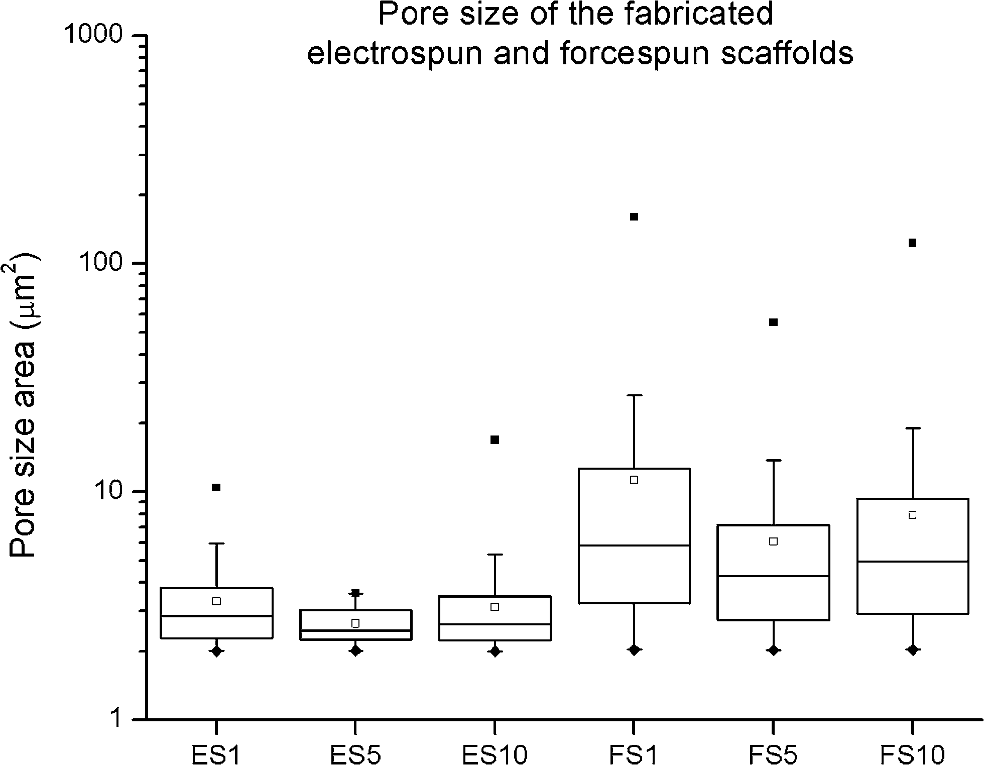 | ||
| Fig. 1 Pore size of the fabricated fibrous scaffolds. The pore sizes measured in the fabricated electrospun and forcespun core–shell scaffolds. ES PCL-1% PF-68 (ES1), ES PCL-5% PF-68 (ES5), ES PCL-10% PF-68 (ES10), FS PCL-1% PF-68 (FS1), FS PCL-5% PF-68 (FS5), FS PCL-10% PF-68 (FS10). The data are presented in box plots with whiskers. ♦ denotes minimum, ■ denotes the maximum and □ denotes the mean value. | ||
Stereological analysis showed that the two samples differed in fibre morphology. The nano/microfibrous morphology of the electrospun scaffolds was shown as a suitable substrate for keratinocyte,22 melanocyte22 and fibroblast growth.22,23 The nanofibres were present in the microfibrous network and supported cell adhesion. Pham et al. observed higher cellular spreading on nanofibrous scaffolds with significantly higher F-actin formation.24 The structure of the electrospun scaffolds was rather planar with a tightly packed fibre network. The sheet-like structure of the scaffold with a lower pore size did not allow complete cell penetration through the scaffold, and the cells were growing in the first 50 μm of the scaffold.12,24,25 However, the planar structure may be favourable for skin tissue engineering. The nanofibrous sheet acts as a barrier-like scaffold, where the cells are localised on the basal part of the wound and the scaffold protects them from environmental damage from the outer environment. On the other hand, the forcespun scaffolds showed more 3D structure. This is mainly due to the dominant presence of microfibres. The fibres were more loosely packed and the mean pore size was higher. The scaffolds showed a median pore size ranging from 4.2 to 5.8 μm2 and a high presence of pores larger than 4 μm2. The common migration protocols for fibroblasts used an 8 μm pore size for migration testing.26 In addition, the mean pore size for cell penetration in vivo was much smaller than the predicted in vitro value. This could relate to individual fibres pushing apart during cell movement.27 In our previous work, we have shown improved penetration of cells in PCL scaffolds prepared by forcespinning compared to electrospinning.19
The scaffolds were functionalised by active molecules promoting cell proliferation. The encapsulation of the PF-68 core and the proteins (contained in the platelet lyophilisate) into the fibres was confirmed by FTIR-ATR spectroscopy. The control PCL fibres showed a typical FTIR spectra with a dominant C![[double bond, length as m-dash]](https://www.rsc.org/images/entities/char_e001.gif) O stretch band at 1750 cm−1 and a typical fingerprinting zone. Control PF-68 showed strong absorption in 2750–3000 cm−1, corresponding to the resonance of C–H groups and resonance in 3500 cm−1 region corresponding to the O–H stretch. In the case of both electrospun and forcespun PCL-PF-68 nanofibres with PF-68 as a core phase, the band corresponding to the O–H stretch band at 3200–3600 cm−1 was present. The band has a broad shape and the absorbance increased with PF-68 concentration from 1% to 10% (Fig. 2). In the case of both ES and FS with 10% PF-68, we have observed an increased C–H stretch peak (2850–3000 cm−1). The change in spectra is in accordance with PF-68 composition containing polyethylene oxide and polypropylene oxide units. Nevertheless, the presence of the platelet lyophilisate resulted in an increased absorbance at 1600 cm−1 corresponding to a C–N stretch of proteins in all samples with lyophilisate.
O stretch band at 1750 cm−1 and a typical fingerprinting zone. Control PF-68 showed strong absorption in 2750–3000 cm−1, corresponding to the resonance of C–H groups and resonance in 3500 cm−1 region corresponding to the O–H stretch. In the case of both electrospun and forcespun PCL-PF-68 nanofibres with PF-68 as a core phase, the band corresponding to the O–H stretch band at 3200–3600 cm−1 was present. The band has a broad shape and the absorbance increased with PF-68 concentration from 1% to 10% (Fig. 2). In the case of both ES and FS with 10% PF-68, we have observed an increased C–H stretch peak (2850–3000 cm−1). The change in spectra is in accordance with PF-68 composition containing polyethylene oxide and polypropylene oxide units. Nevertheless, the presence of the platelet lyophilisate resulted in an increased absorbance at 1600 cm−1 corresponding to a C–N stretch of proteins in all samples with lyophilisate.
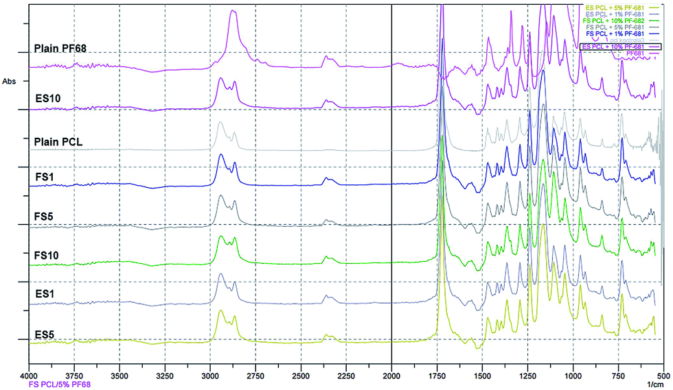 | ||
| Fig. 2 FTIR-ATR spectra of electrospun and forcespun PCL and PCL-PF-68 nanofibres. Spectra of PCL, PF-68, ES PCL-1% PF-68 (ES1), FS PCL-1% PF-68 (FS1), ES PCL-5% PF-68 (ES5), FS PCL-5% PF-68 (FS5), ES PCL-10% PF-68 (ES10), FS PCL-10% PF-68 (FS10). The difference in spectra indicate the resonance of PF-68 groups at 3200–3600 cm−1 (O–H stretch), 2775–3000 cm−1 (C–H stretch) and 1600 cm−1 (C–N stretch). | ||
Platelet lyophilisate analysis
Tissue repair/wound healing is profoundly modulated by cytokines, chemokines and number of growth factors,28 including (but not limited to) basic fibroblast growth factor (bFGF), platelet-derived growth factor (PDGF), vascular endothelial growth factor (VEGF), epidermal growth factor (EGF), or transforming growth factor beta (TGF-β).29 However, the use of synthetic growth factors is rather limited. The underlying reason may be their delivery in supraphysiological doses, or rapid breakdown and clearance from the site of action.28 Furthermore, there are still concerns regarding their safety and cost-effectiveness.30 Such limitations can be overcome using platelets.Platelets play a crucial role in wound healing since, via growth factors (GF) stored in their α-granules, they help to maintain the fine balance in the healing cascade. In their native state, autologous platelets have been used in clinical practice in wound healing applications, dental and maxillofacial surgery or sports and veterinary medicine.31 However, the use of such preparations is hindered by a lack of standardisation and considerable interindividual variability in the GF content. It has been shown that the concentration of the bioactive molecules contained in platelets may be influenced by the platelet count, gender and age,32 and as well as comorbidities, particularly different GF levels were found in patients suffering from diabetes and in non-diabetics.33 The illustrated limitations can be overcome using allogeneic platelet products. Furthermore, the shelf-life of fresh platelets used in clinical practice is 5 days, due to the increased risk of bacterial contamination and loss of their haemostatic function. It results in the discarding of up to 20% of the platelet units,34 although it has been shown that platelets retain their proliferative potential for up to 21 days of storage.35 Recently, we have reported the use of native platelets immobilised by simple adhesion to the surface of PCL nanofibres, and observed promoted proliferation and metabolic activity of fibroblasts22,23 and keratinocytes.22 Furthermore, the use of platelet lysate in keratinocyte and fibroblast culture on PCL nanofibers was optimised.36
In the current study, the protein content in the platelet lyophilisate was measured to be 0.48 mg mL−1. The BioPlex multiplex assay was performed to determine the concentration of specific mediators in the platelet lyophilisate (Fig. 3). It was shown that platelet lyophilisate contained various pro- and anti-inflammatory mediators; the most abundant proinflammatory mediator was IL-17. Additionally, chemokines and growth factors were found in the platelet lyophilisate, which are of great importance in tissue engineering applications. The most represented chemokine and growth factor were RANTES and PDGF-BB, respectively.
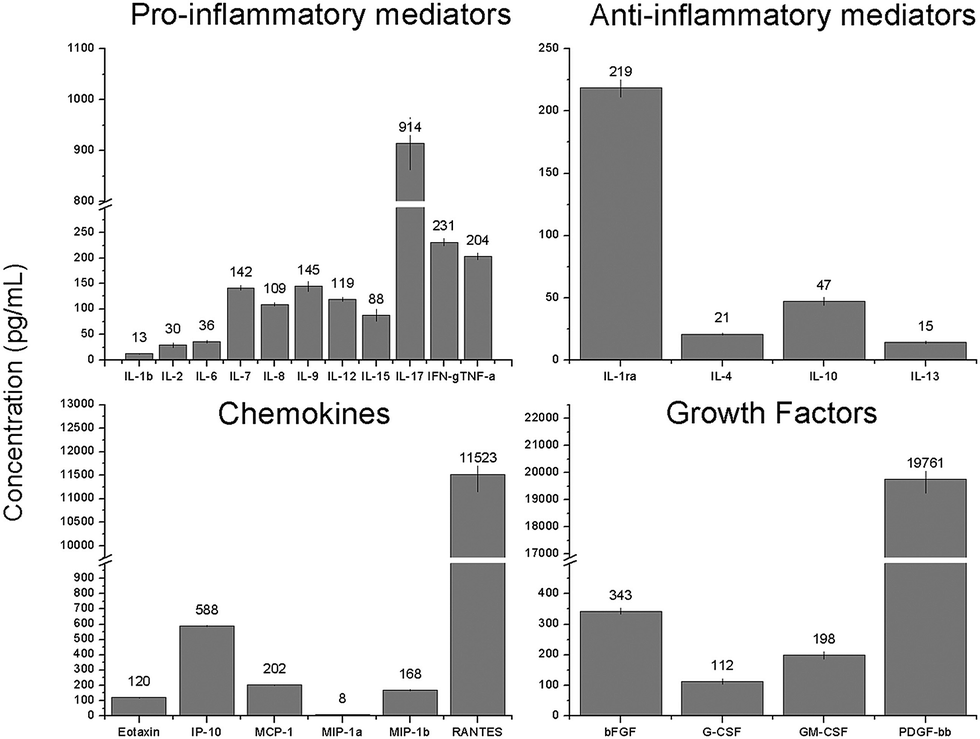 | ||
| Fig. 3 Concentration of the assayed mediators in the platelet lyophilisate. | ||
The acquired data showed comparable levels of cytokines, chemokines and growth factors detected by the XMAP assay in platelet lyophilisate encapsulated into forcespun nanofibres,19 native platelets adhered to the surface of forcespun PCL nanofibers17 and the platelet lysate used in cell culture.36 The data demonstrate the preservation of growth factors during the freeze-drying of the platelets. Such preparation provides an improvement in shelf-life, since freeze/dried platelets can be kept functional for up to two years.37 Additionally, by lyophilisation of the platelets, their loading into nanofibres is facilitated. The concentration of the platelet lyophilisate in the spinning solutions can be tailored to the particular requirements, and, furthermore, the lyophilisate is soluble in suitable solvents.
Release of platelet lyophilisate from the core–shell fibrous scaffolds
The release of platelet lyophilisate encapsulated into the core–shell electrospun and forcespun nanofibres was evaluated. The Fig. 4A, illustrating the cumulative release, shows the dependence of the absolute amount of the encapsulated platelet lyophilisate on the concentration of the core polymer PF-68 (1 to 10%), whereas the Fig. 4B, illustrating the relative release, shows the release rate of the encapsulated platelet lyophilisate and its dependence on the PF-68 core concentration which is associated with release rate. Relative total protein release (Fig. 4B) shows, that in all the samples, the proteins were, in the first days, released at a higher rate (burst). On day 1, the amount of the protein released ranged from 20 to 24 percent in all the tested samples. The burst release was followed by a sustained release until day 30. In the case of the electrospun fibres, the release rate increased with an increasing PF-68 core concentration. The half-time of release for the ES1 sample (1% PF-68 fibres) was determined at 10.4 days. In the case of the higher core concentrations, the release was faster and half-time was shifted to 5.3 days for ES5 (5% PF-68) and 4.2 days for ES10 (10% PF-68). Similarly, in the case of the samples prepared by forcespinning, the half-time of the release was decreasing with the PF-68 concentration. In the case of FS1 (1% PF-68), it was 6.5 days and in FS5 (5% PF-68) and FS10 (10% PF-68) it decreased to 4 and 3.6 days, respectively. The faster release from the samples correlates with the behaviour in our previous studies. The emulsion electrospinning results in the formation of fibres for long-term delivery of active molecules.38 In the case of centrifugal spinning,19 the fibres showed a similar release pattern and the mean release time was shorter than in the studies with electrospun fibres.39–41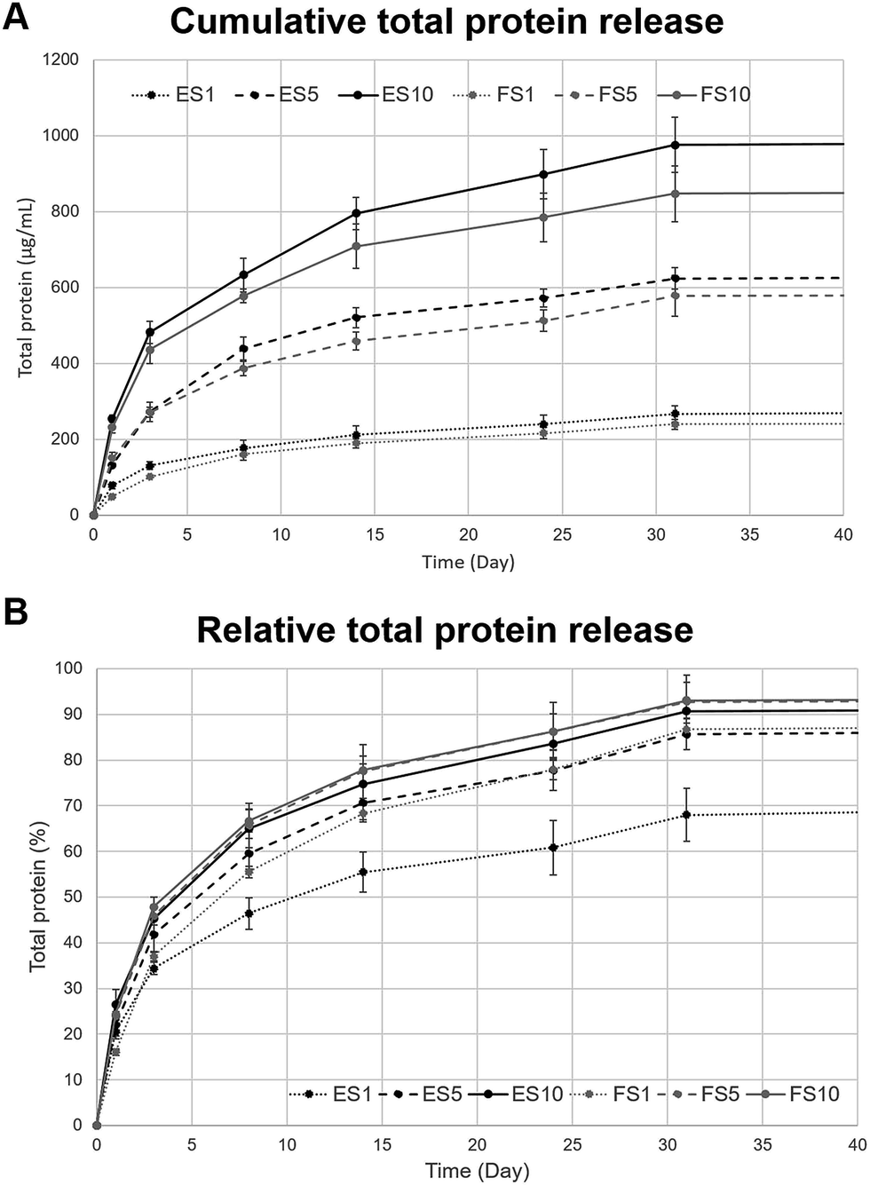 | ||
| Fig. 4 Total protein release from the electrospun and forcespun fibrous scaffolds. (A) Cumulative total protein release, (B) relative total protein release. ES PCL-1% PF-68 (ES1), FS PCL-1% PF-68 (FS1), ES PCL-5% PF-68 (ES5), FS PCL-5% PF-68 (FS5), ES PCL-10% PF-68 (ES10), FS PCL-10% PF-68 (FS10). Lines in black colour represent the protein release from the electrospun scaffolds, lines in grey colour represent forcespun scaffolds. | ||
Nevertheless, the amount of the total protein released (Fig. 4A) was highest in the groups containing 10% PF-68 as a core phase, for both electrospun and forcespun fibres. With a decreasing PF-68 concentration, the amount of the released proteins decreased and was lowest for the 1% PF-68. The higher total cumulative release of protein in samples with a higher PF-68 concentration may relate to the higher number of PF-68 core micelles in the structure of the fibre. This hypothesis is confirmed by the higher number of PF-68 core droplets observed during the emulsion centrifugal spinning process.19 The higher number of core droplets results in a higher droplet interconnection and a lower number of the isolated droplets. Upon interaction of fibres with high PF-68 concentration with aqueous solvents, the water diffuses into these droplet pores and dissolves the core droplets, resulting in a higher and faster release. The droplet interconnection enables further diffusion and desorption from deeper droplets without the need for fibre degradation. In the case of scaffolds with a lower PF-68 concentration, the number of interconnected droplets available for release is lower, resulting in a more sustained, but less intensive release. A long-term release is in the case of fibres driven both by diffusion and degradation mechanisms.42 The PCL fibre degradation is slow43 and plays a less dominant role. The surface degradation of the fibres was observed in the SEM images taken on day 1 and 17 of the experiment (ESI Fig. 2†). On day 1, following a short-term incubation in aqueous solvents, the samples showed smooth surface indicating tight polymer chain interconnection. On the other hand, after 17 days of incubation, the changes in fibre surface morphology were apparent. The fibres had more structured surface connected with changes in polymer chain organization. Such changes resulted in more porous structure of the fibres and may play role in release from the scaffolds. Besides erosion of the fibre surface, the release is regulated by the rate of drug and water diffusion. The diffusion is driven via the interconnected droplets and through nanopores in the PCL fibre structure, observed previously.7 The hypothesis correlates both with the release half-times and the amount of the total protein released from our scaffolds.
The release from the fibres correlates with the time frame of skin regeneration. When the integrity of the epidermal barrier is disrupted, the clotting cascade is activated and platelets release their numerous GF (EGF, VEGF, PDGF). Haemostasis occurs, resulting in the production of a clot covering the wound, together with the inflammation phase, which ensures proper necrotic tissue debridement and the vascular and cellular response to the injury. The inflammation phase lasts up to 3 days.44 Simultaneously, within hours after the initial injury, re-epithelialisation starts via EGF and FGF stimulation of the keratinocyte migration and proliferation. The migration and proliferation of keratinocytes is followed by infiltration of the provisional matrix by neighbouring fibroblasts, as the released PDGF attracts fibroblasts and stimulates their proliferation and a massive synthesis of the new ECM.29,45 Additionally, the VEGF induces angiogenesis. By day 5 after the injury, the maximum formation of blood vessels and granulation tissue occurs.44 Once the wound is closed, the keratinocytes undergo stratification and differentiation, in order to restore the epidermal barrier. In the later stages of the ECM synthesis and remodelling, TGF-β plays an important role as it stimulates the synthesis of collagen (type I and III). The precise coordination of the indicated processes and appropriate GF levels is rather complex, and thus small deviations may result in an inability of the wound to close.29 The molecular mechanisms behind wound healing highlight the suitability of platelets as a source of growth factors. The pro-healing cytokines are present in platelets, and after their incorporation to fibres, the scaffolds stimulate progress through the wound healing phases. The time-frame of the protein release from our scaffolds correlates with the duration of the wound healing phases. The half-time of release between 3-5 days for samples with 5% and 10% PF-68 provides optimal stimulation times for early and middle phases of wound healing. Nevertheless, the prolonged release enables the extension of wound dressing exchange intervals and helps to decrease the economic burden related to the successful healing of wounds.
Fibroblasts respond to released platelet lyophilisate in a dose-dependent manner
To compare the importance of both the scaffold morphology and the drug delivery rate, the prepared fibres were tested using skin cells. The human skin is formed by stratified epithelium of keratinocytes, present in the epidermal layer. The dermal layer is formed by fibroblasts acting as key collagen I-producing cells responsible for skin mechanical properties.The platelet lyophilisate loaded into the fibres was utilised for stimulation of fibroblast proliferation and their metabolic activity. The biocompatibility of the prepared fibrous scaffolds was tested using 3T3 fibroblasts. The metabolic activity of the seeded fibroblasts was tested using the MTS assay on days 1, 3, 7, 14 and 17 (Fig. 5). The data showed comparable results regarding the stimulation of metabolic activity of the seeded fibroblasts on the electrospun (Fig. 5A) and forcespun scaffolds (Fig. 5B). In both the electrospun and forcespun samples, the samples loaded with the highest amount of the platelet lyophilisate (ES10 or FS10) showed superior properties in terms of stimulation of fibroblast metabolic activity. Furthermore, statistical analysis of all the acquired data showed, that the metabolic activity of the seeded fibroblasts on the forcespun sample FS10 (highest loading capacity) was significantly higher than all the tested samples (electrospun and forcespun) on day 14 and higher than the electrospun samples on day 17.
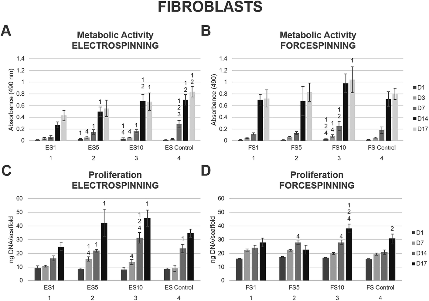 | ||
| Fig. 5 Metabolic activity and proliferation of fibroblasts seeded on the electrospun and forcespun scaffolds on days 1, (3,) 7, 14 and 17. (A) Metabolic activity of fibroblasts seeded on the electrospun scaffolds, (B) metabolic activity of fibroblasts seeded on the forcespun scaffolds, (C) proliferation of fibroblasts on electrospun scaffolds, (D) proliferation of fibroblasts on forcespun scaffolds. ES PCL-1% PF-68 (ES1), ES PCL-5% PF-68 (ES5), ES PCL-10% PF-68 (ES10), ES PCL control, FS PCL-1% PF-68 (FS1), FS PCL-5% PF-68 (FS5), FS PCL-10% PF-68 (FS10), FS PCL control. D1–D17 denote experimental days. Statistical significance was set at p < 0.05. | ||
The proliferation data acquired on the days corresponding to the MTS assay showed a similar pattern (Fig. 5C and D). The statistical analysis of all the fibrous samples showed a significantly improved initial adhesion of fibroblasts on all the forcespun samples on day 1 when compared to the electrospun samples. Such a trend was maintained until day 14 of the experiment, when all the differences between the forcespun samples and the electrospun samples were levelled out. The samples with the highest loading capacity (ES10, FS10) yielded the most promising results in stimulation of the fibroblast proliferation.
A confocal microscopy study of the morphology of the cells showed that on day 7 of the experiment, the cells showed similar morphology on all scaffolds. However, after a longer culture the cell morphology among the scaffolds began to differ. On the scaffolds with the lower concentrations of PF-68, the cells were overlapped and more stratified. On the other hand, the cells on the higher concentration were more isolated and the boundaries between the cells were more pronounced (Fig. 6). Furthermore, the fibroblasts were visualised using scanning electron microscopy on day 7 (Fig. 7). On the scaffolds with the lower platelet lyophilisate content, the cells formed clusters. However, with the increasing concentration of the platelet lyophilisate, the cells were well spread and exhibited morphology typical for the culture of fibroblasts on the PCL scaffolds. To emphasize and more accurately observe the effect of the released platelet lyophilisate, the seeded cells were cultured under serum-reduced conditions (5% FBS), suggesting that the lower platelet lyophilisate was not enough the stimulate proper fibroblast proliferation.
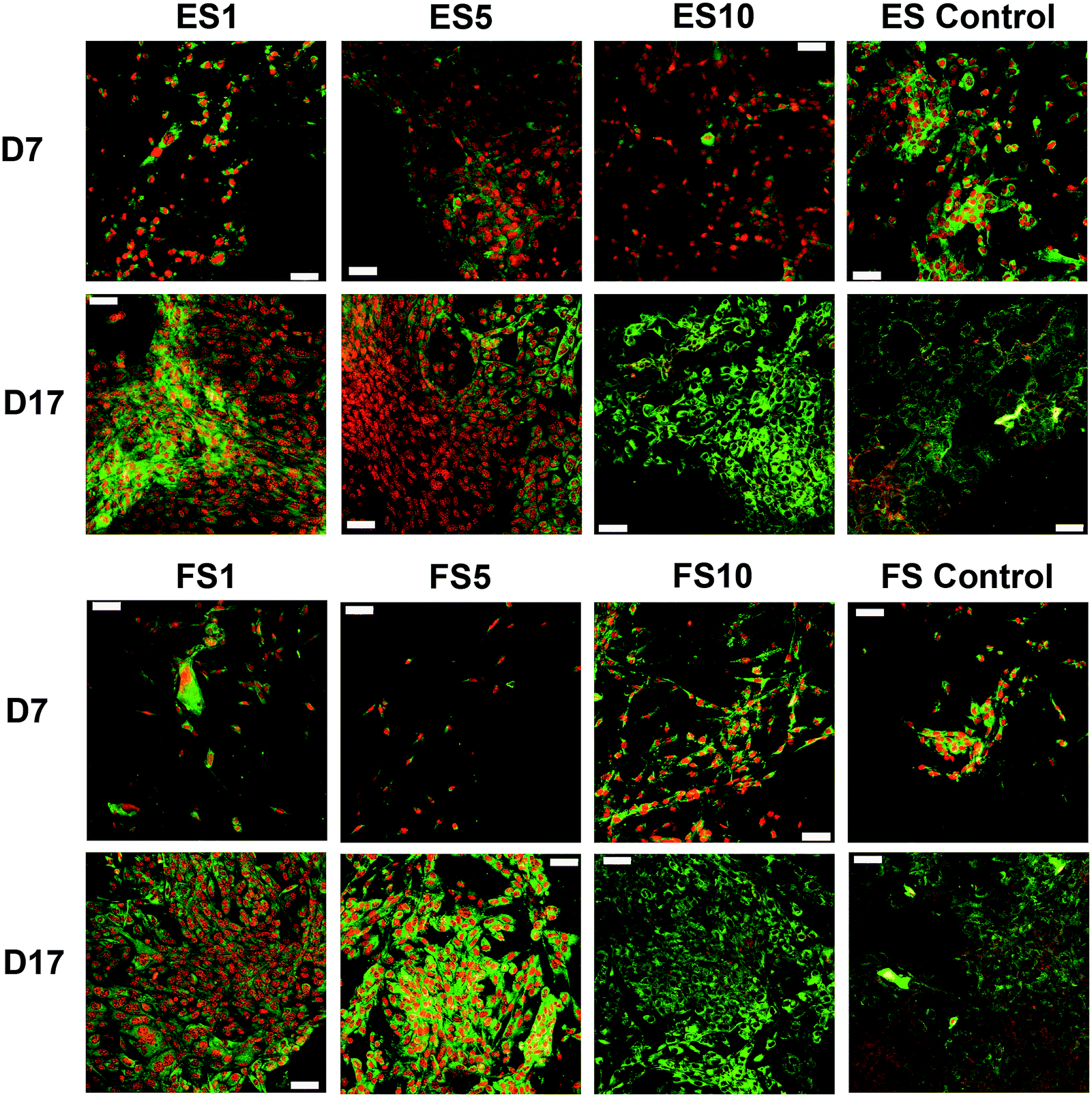 | ||
| Fig. 6 Confocal microscopy images of the fibroblasts seeded on the electrospun and forcespun scaffolds on days 7 and 17. ES PCL-1% PF-68 (ES1), ES PCL-5% PF-68 (ES5), ES PCL-10% PF-68 (ES10), ES PCL control, FS PCL-1% PF-68 (FS1), FS PCL-5% PF-68 (FS5), FS PCL-10% PF-68 (FS10), FS PCL control. Green colour depicts cellular biomembranes (staining by DiOC-6), red colour cell nuclei (propidium iodide staining). Magnification 200×, scale bar 50 μm. | ||
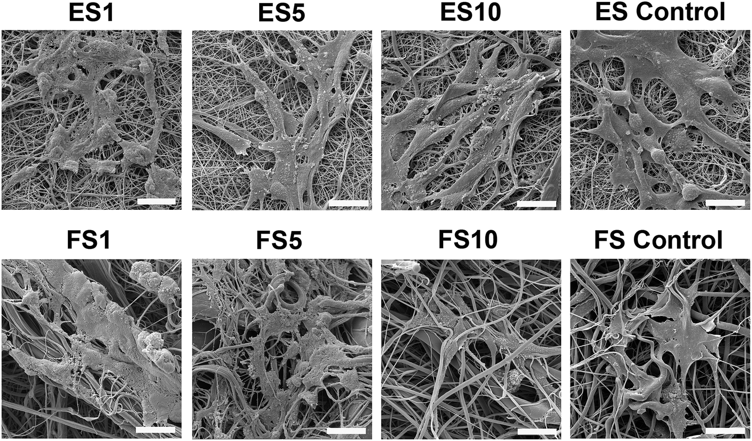 | ||
| Fig. 7 SEM images of fibroblast morphology on electrospun and forcespun scaffolds. The samples with the seeded cells were fixed and dehydrated on day 7 of the experiment. ES PCL-1% PF-68 (ES1), ES PCL-5% PF-68 (ES5), ES PCL-10% PF-68 (ES10), ES PCL control, FS PCL-1% PF-68 (FS1), FS PCL-5% PF-68 (FS5), FS PCL-10% PF-68 (FS10), FS PCL control. Magnification 3000×, scale bar 20 μm. | ||
The results indicate that the fibroblasts showed a similar growth pattern on both the scaffold types. Polycaprolactone in the form of fibrous scaffold was shown to stimulate fibroblast proliferation and metabolic activity.22,23,46 The results indicated a similar affinity of fibroblasts to both nano/microfibrous and microfibrous scaffolds. The structure of both scaffolds was similar to the structure of the ECM of the connective tissues and the fibroblasts showed good adhesion and proliferation on the scaffolds. In addition, the platelet lyophilisate stimulated cell metabolic activity in a rather dose-dependent manner. The samples with the addition of PF-68 and the lowest concentration of the growth factors, lead to a decrease in metabolic activity. This may relate to the altered release characteristics or the dominant inhibitory effect of the released chemokines. The 1% PF-68 fibres showed the slowest release rate and the lowest total protein content. The most dominant chemokines in platelet lyophilisate were IL-17 and RANTES. At low concentrations, these proteins were the most dominant chemokines released from the fibres. IL-17 was shown to stimulate the production of pro-angiogenic factors in fibroblasts and thus mediate fibroblast-induced angiogenesis.47 In the groups with higher PF-68 concentrations, the amount of the total released protein was higher. With the increasing total protein concentration, the bioavailability of the growth factors, which act as fibroblast mitogens, increased as well (i.e. PDGF, EGF)48,49 and resulted in improved proliferation and metabolic activity. Such findings are in concordance with the results of Sovkova et al., who found a dose-dependent effect of human platelet lysate on fibroblasts cultured on plain electrospun PCL scaffolds.36 Additionally, the positive effect of growth factors released from platelets adhered to the PCL nanofibrous scaffold, was observed in fibroblast culture.22
Keratinocytes prefer 2D structured fibrous scaffolds
Keratinocytes are specialised epithelial cells that form the outer layer of the skin, and thus provide the skin with a barrier function against the outer environment. The biocompatibility of the prepared scaffolds was tested in vitro using XB2 keratinocytes. On days 1, 3, 7, 14 and 17, the MTS assay was performed (Fig. 8). The data acquired from the electrospun scaffolds (Fig. 8A) showed improved metabolic activity of keratinocytes on scaffolds ES5 and ES10 and ES control when compared to the ES1 scaffold through the first 14 days of the experiment. On day 14, the keratinocytes seeded on the ES5 scaffold showed higher metabolic activity when compared to the ES control sample. Additionally, on day 17 the metabolic activity of keratinocytes seeded on the ES5 sample was significantly higher than all the other electrospun samples (ES1, ES10 and ES control). No such trend was observed on the forcespun samples (Fig. 8B). The samples FS5 and FS10 showed improved metabolic activity of the cells at the beginning of the experiment (days 1 and 3), however, all the differences were levelled out by day 7 and no statistically significant difference in cellular metabolic activity was observed until the end of the experiment. The overall statistical analysis of the metabolic activity of keratinocytes seeded on the fibrous samples showed, that on day 14 of the experiment the electrospun samples ES5, ES10 and the control sample exhibited higher metabolic activity of the seeded keratinocytes when compared to all the forcespun samples (FS1, FS5, FS10 and FS control). However, on the last day of the experiment, improved metabolic activity regarding the electrospun samples was found on samples ES1 and ES5.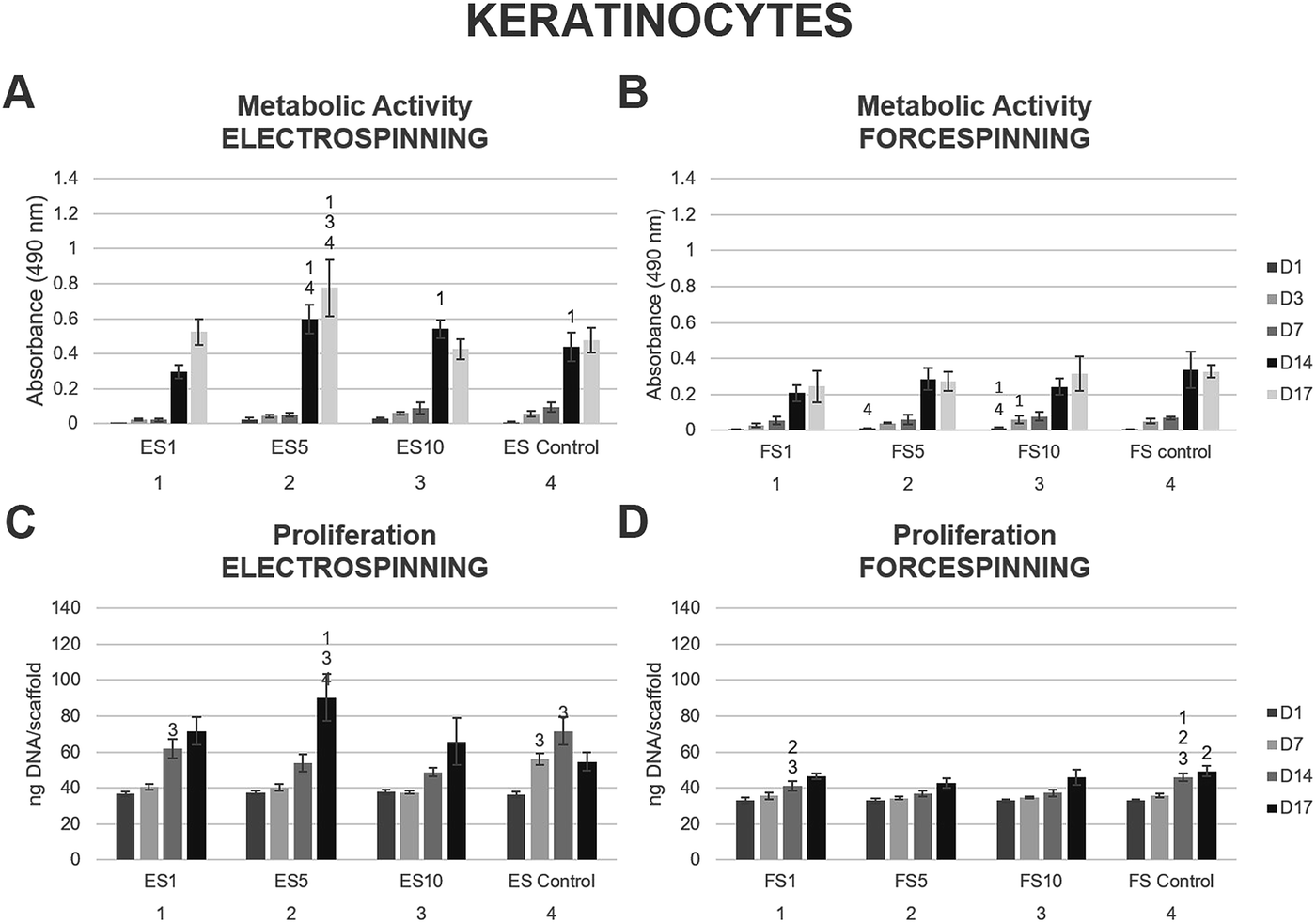 | ||
| Fig. 8 Metabolic activity and proliferation of keratinocytes seeded on the electrospun and forcespun scaffolds on days 1, (3,) 7, 14 and 17. (A) Metabolic activity of keratinocytes seeded on the electrospun scaffolds, (B) metabolic activity of keratinocytes seeded on the forcespun scaffolds, (C) proliferation of keratinocytes on electrospun scaffolds, (D) proliferation of keratinocytes on forcespun scaffolds. ES PCL-1% PF-68 (ES1), ES PCL-5% PF-68 (ES5), ES PCL-10% PF-68 (ES10), ES PCL control, FS PCL-1% PF-68 (FS1), FS PCL-5% PF-68 (FS5), FS PCL-10% PF-68 (FS10), FS PCL control. D1–D17 denote experimental days. Statistical significance was set at p < 0.05. | ||
Furthermore, cell proliferation on the scaffolds was determined using PicoGreen® fluorescence dye on days 1, 7, 14 and 17. The data showed increasing proliferation on the electrospun scaffolds enriched with the platelet lyophilisate (ES1, ES5 and ES10) through the whole experiment (Fig. 8C). On the last day of the experiment, keratinocytes seeded on the ES5 scaffold showed superior proliferation to all the other electrospun samples. However, the proliferation of keratinocytes seeded on the forcespun samples (Fig. 8D) was not as pronounced as on the ES samples, and the effect of platelet lyophilisate was not observed.
The optimal concentration of the released bioactive molecules for keratinocyte culture seemed to follow the release pattern of fibrous scaffolds prepared using 5% PF-68. Keratinocytes cultured on such scaffolds showed a statistically significant improvement in metabolic activity and cell proliferation, not only in comparison to the PCL control, but to the other platelet-functionalised samples as well. In our previous study, all the platelet-functionalised PCL samples showed improved keratinocyte metabolic activity and proliferation without significant differences among them,22 suggesting the other concentrations of the platelet-derived bioactive molecules in the current study were either too high (ES10) and rather inhibited the keratinocyte proliferation, or too low (ES1) and, in terms of improved cellular proliferation, insufficient. The dose-dependent effect of platelet lyophilisate in keratinocyte culture was also observed in blend PCL nanofibers.50 Correspondingly, Sovkova et al. investigated the optimal composition of cell culture media supplemented with platelet lysate (PL) in keratinocytes. According to the results, the stimulation of proliferation of keratinocytes was achieved with increasing PL concentration, with the optimal concentration determined as 7% (v/v) PL36.
The data obtained in the proliferation assay were confirmed by the confocal microscopy study (Fig. 9). The acquired images of day 17 of the experiment showed significantly improved proliferation of keratinocytes on the ES5 sample, where the keratinocytes formed confluent layers and exhibited stratified morphology. Although the increase in cell numbers from day 7 to day 17 was not so dramatic on the rest of the samples (ES1, ES10, FS1, FS5, FS10 and controls), the proliferation of keratinocytes was clearly visible.
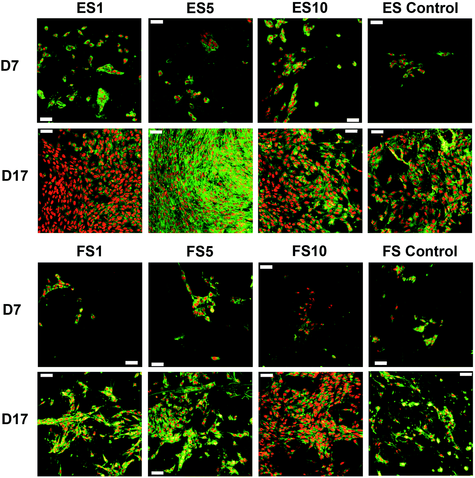 | ||
| Fig. 9 Confocal microscopy images of the keratinocytes seeded on the electrospun and forcespun scaffolds on day 7 and 17. ES PCL-1% PF-68 (ES1), ES PCL-5% PF-68 (ES5), ES PCL-10% PF-68 (ES10), ES PCL control, FS PCL-1% PF-68 (FS1), FS PCL-5% PF-68 (FS5), FS PCL-10% PF-68 (FS10), FS PCL control. Green colour depicts cellular biomembranes (staining by DiOC-6), red colour cell nuclei (propidium iodide staining). Magnification 200×, scale bar 50 μm. | ||
On the 2D electrospun samples, the cultured keratinocytes formed confluent layers. The most promising composition of the prepared fibres, in terms of promotion of stratified epithelium formation, is shown by the ES5 sample. Such findings confirmed that in favourable conditions keratinocytes tend to mature and form stratified layers. However, on all the forcespun samples, variable-sized islands of the cultured cells were found, regardless of the presence and/or concentration of the platelet-derived bioactive molecules. This indicates suboptimal morphology of the tested forcespun nanofibrous layers for the stimulation of keratinocyte epithelium formation. Such findings are in concordance with the findings of Kempf et al., who investigated the influence of fibre diameter and pore size of denatured collagen microfiber scaffolds on keratinocyte adhesion, proliferation, migration and penetration into the scaffold.51 The results showed that the porous scaffold promoted cell adhesion and survival, however hampered keratinocyte migration and penetration. Thus, the data suggest suitability of the morphology of the electrospun layers for keratinocyte stimulation.
Additionally, scanning electron microscopy was used to visualise the cells adhered to the nanofibrous scaffolds on day 7 (Fig. 10). The images showed well spread cells with morphology characteristic for keratinocytes.
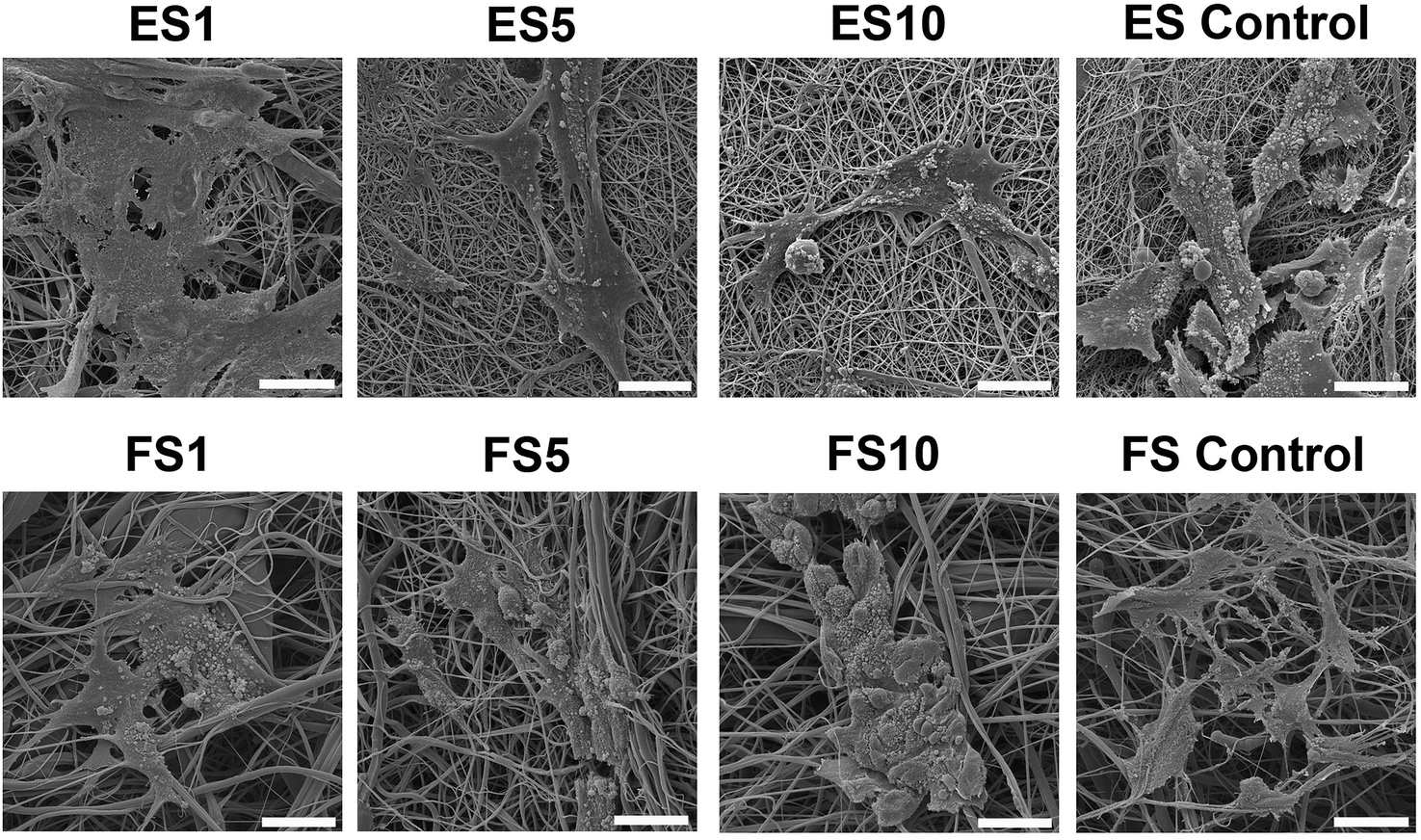 | ||
| Fig. 10 SEM images of keratinocyte morphology on electrospun and forcespun scaffolds. The samples with the seeded cells were fixed and dehydrated on day 7 of the experiment. ES PCL-1% PF-68 (ES1), ES PCL-5% PF-68 (ES5), ES PCL-10% PF-68 (ES10), ES PCL control, FS PCL-1% PF-68 (FS1), FS PCL-5% PF-68 (FS5), FS PCL-10% PF-68 (FS10), FS PCL control. Magnification 3000×, scale bar 20 μm. | ||
In the case of electrospun scaffolds, the cells were observed on the surface of the fibres. The structure of the scaffold was mimicking basal lamina. On the other hand, in the case of forcespun scaffolds, the bigger pore size lead to an accumulation of cells to clusters and spheroid like structures. The cells were less spread and colonisation of the scaffold was slower. This phenomenon was connected to the different scaffold structure. The scaffold with a smaller pore size supported cell adhesion, but did not allow cell penetration to its deeper layers, stimulating only cell interaction on superficial layers and pushing the cells to more epithelial tissue formation.
The superior morphological properties of the nanofibres compared to microfibres were shown in chitin electrospun fibrous scaffolds52 and silk fibroin matrices.53 The submicron diameters of the nanofibrous scaffolds significantly promoted cell adhesion and spreading, compared to the microfibres. Additionally, the dependency of keratinocyte proliferation on the strand diameter of 3D plotted collagen fibres was investigated. With the increasing strand diameter, the proliferation rate of keratinocytes decreased.54 This indicates the importance of proper morphology of the fibrous scaffolds in skin tissue engineering constructs.
Besides morphological mimicking, the release of growth factors stimulated cell proliferation. Gümüşderelioğlu et al. cultured human keratinocytes on PCL and PCL/collagen blend electrospun nanofibrous matrices with immobilised EGF on their surface. The nanofibrous texture of the scaffolds affected cellular organisation. Furthermore, the drug delivery of the immobilised EGF to the surface of the nanofibres resulted in rapid proliferation of keratinocytes in comparison to the control samples without the EGF.55 The study of Choi et al. showed that EGF conjugated to the surface of the PCL/PEG nanofibrous scaffolds and prolonged the bioavailability of the EGF in an animal diabetic wound model in comparison to the PCL/PEG nanofibres soaked in the EGF solution. Such treatment accelerated the wound closure, especially in its early stages. These studies have illustrated the necessity of a sustained release of the growth factors, as most of the GF administered as exogenous additives failed in clinical practice, mainly due to the high proteolytic activities in the wound.56
In our case, platelet lyophilisate was used for the stimulation of keratinocytes. The results showed both improved proliferation and metabolic activity on fibrous scaffolds releasing the platelet lyophilisate. Such results are in accordance with our previous work, with platelets adhering to the surface of the PCL nanofibres22 and platelet lysate used as a cell culture supplement.36
Experimental
Platelet lyophilisate preparation and Bio-Plex analysis
Fresh human leukocyte-depleted platelet concentrate derived from buffy coat in additive solution was obtained from a blood transfusion service (Sumperk, Czech Republic). According to the Czech legislation of blood transfusion, blood products not used for therapy can be used for scientific purposes. Therefore, approval from an ethics committee was not necessary for this study. All donors signed an informed consent, agreeing to the use of their blood for scientific purposes. The platelet concentration in the bag was 917 × 109 platelets per L. The platelets were centrifuged (3100g, 10 min) and resuspended with distilled water. Subsequently, the solution was aliquoted, frozen (−80 °C) and thawed (37 °C) three times in total to disrupt the platelet cellular membranes. The lysate was centrifuged (4100g, 15 min) to get rid of the cellular debris. Subsequently, the lysate was lyophilised under 480 mTorr (VirTis BenchTop Pro Freeze Dryer, SP Scientific, PA, USA) for 24 hours. The lyophilised platelet lysate was stored at −80 °C until use.To characterise the cytokine content in the platelet lyophilisate, the Bio-Plex 200 Multiplex System (Bio-Rad Laboratories, CA, USA) was employed. The commercially available cytokine panel (Bio-Plex ProTM Human Cytokine 27-plex Assay, Bio-Rad Laboratories, CA, USA) was used, in accordance with the manufacturer's instructions. The assay allows multiple cytokines to be quantified simultaneously in one well. The following cytokines were quantified: interleukin-1b (IL-1b), interleukin 1ra (IL-1ra), interleukin-2 (IL-2), interleukin-4 (IL-4), interleukin-5 (IL-5), interleukin-6 (IL-6), interleukin-7 (IL-7), interleukin-8 (IL-8), interleukin-9 (IL-9), interleukin-10 (IL-10), interleukin-12 (IL-12), interleukin-13 (IL-13), interleukin-15 (IL-15), interleukin-17 (IL-17), granulocyte-colony stimulating factor (G-CSF), granulocyte-macrophage colony stimulating factor (GM-CSF), interferon-gamma (INF-γ), tumor necrosis factor-α (TNF-α), monocyte chemoattractant protein-1 (MCP-1), CXCL10 chemokine (IP-10), MIP-1a, MIP 1b (CCL-4), RANTES, eotaxin (CCL-11), platelet-derived growth factor (PDGF), basic-fibroblast growth factor (bFGF), and vascular endothelial growth factor (VEGF). The protein content in the platelet lyophilisate was determined using Quant-iT™ Protein Assay Kit, (Invitrogen Life Technologies, CA, USA) in accordance with the manufacturer's instructions.
Scaffold fabrication and sample preparation
Fibrous scaffolds were prepared by either core/shell electrospinning (ES) or forcespinning (FS) technology. In both cases, the shells of fibres were made from polycaprolactone (PCL) with a molecular weight of 45![[thin space (1/6-em)]](https://www.rsc.org/images/entities/char_2009.gif) 000 Da (Sigma Aldrich, Germany). The core phase was prepared using a combination of poloxamer 188 (Pluronic F68, PF-68; Sigma Aldrich, Germany) with platelet lyophilisate. The precise composition of the fibres is shown in Table 1.
000 Da (Sigma Aldrich, Germany). The core phase was prepared using a combination of poloxamer 188 (Pluronic F68, PF-68; Sigma Aldrich, Germany) with platelet lyophilisate. The precise composition of the fibres is shown in Table 1.
| Sample | Core polymer | Shell polymer | Lyophilisate |
|---|---|---|---|
| ES1 | 1% PF-68 | 24% PCL | 15 mg mL−1 |
| ES5 | 5% PF-68 | 24% PCL | 15 mg mL−1 |
| ES10 | 10% PF-68 | 24% PCL | 15 mg mL−1 |
| ES control | — | 24% PCL | — |
| FS1 | 1% PF-68 | 40% PCL | 15 mg mL−1 |
| FS5 | 5% PF-68 | 40% PCL | 15 mg mL−1 |
| FS10 | 10% PF-68 | 40% PCL | 15 mg mL−1 |
| FS control | — | 40% PCL | — |
Electrospun fibrous scaffolds were prepared using the needleless emulsion electrospinning method (water-in-oil emulsification, W/O). A 24% solution (w/v) of PCL was dissolved in chloroform and ethanol (volume ratio 9:1). Emulsification was performed with water phase containing PF-68 and the platelet lyophilisate. First, the 30% (w/v) PF-68 dissolved in 90% ethanol was mixed with the lyophilisate dissolved in 50% ethanol and pure ethanol to achieve a solution of 1% (w/v), 5% (w/v) or 10% (w/v) PF-68. The final core mixture contained 70% ethanol. Control samples (PCL) were prepared by direct electrospinning of 24% PCL. All samples were electrospun using a linear rod electrode on a Nanospider NS 500 device (Elmarco, Czech Republic). A high-voltage source (Spellman HV, NY, USA) generated voltages of up to 140 kV and the polymer solution was connected to the high-voltage source. The voltage used for spinning was between 70 kV, distance was set at 35 cm and polymer flow rate was 50 mL h−1. Electrospun nanofibers were deposited on the collecting spunbond textile.
The emulsion centrifugal spinning technology is based on W/O emulsification procedure followed by centrifugal spinning processing. First, the core phase was prepared. The 30% (w/v) Pluronic F-68 dissolved in 90% ethanol was mixed with the platelet lyophilisate dissolved in 50% ethanol and pure ethanol, to achieve a solution of 1% (w/v), 5% (w/v) or 10% (w/v) PF-68. The mixing process was performed by drop-wise mixing of the lyophilisate to the agitated PF-68 solutions, followed by sonication. The final core mixture contained 70% ethanol. The emulsion of PF-68 and proteins was subsequently emulsified with 50% PCL dissolved in chloroform to obtain 40% PCL dissolved in chloroform: ethanol. The ratio of the chloroform phase to the ethanol phase was 4:1. The ethanol phase was added drop-wise under stirring. The prepared emulsion was immediately processed by the centrifugal spinning process. The control sample was prepared by the spinning of 40% (w/v) PCL in chloroform: ethanol solution. The centrifugal spinning was performed by forcespinning process on Cyclone L-1000 MD (Fiberio, USA). All samples were processed by G30 needles at 11000 rpm and a collector distance of 10 cm. The fibres were collected on a vacuum assisted deposition system to prepare more condensed samples.
Scaffold characterisation (SEM, FTIR)
The morphology of the prepared electrospun and forcespun nanofibers was characterised using scanning electron microscopy (SEM). The samples seeded with cells were fixed with 2.5% glutaraldehyde on day 7 of the experiment. Upon fixation, the samples were dehydrated with ethanol changes and treated with hexamethyldisilazane (HMDS). Afterwards, the samples were sputter coated with gold using a Quorum Q150RS (Quorum, UK) device. Vega3 SBU (Tescan, Czech Republic) was used to acquire the images. The fibre diameter and pore size of the prepared meshes was determined using ImageJ software from at least 200 independent measurements.Fourier-transformation infrared spectroscopy with attenuated total reflectance (FTIR-ATR) was performed on IRaffinity 1 system (Shimazu). All samples were moulded into tablets by 2 t press. The measurement was performed in the range of 500–4200 cm−1 with Happ-Gazel apodization.
Total protein release from the lyophilisate-containing samples
To assess the release kinetics from the prepared samples, the total protein concentration was determined on days 1, 3, 8, 14, 24 and 31. From each sample, 80 mg of the nanofibres was weighed and immersed in 1 mL of PBS. On each day, the PBS was replaced and the collected samples were frozen until analysis. To determine the concentration of the total protein released from the nanofibrous samples, the Quant-iT™ Protein Assay Kit (Invitrogen Life Technologies, CA, USA) was used in accordance with the manufacturer's protocol.Cell culture & seeding
Murine XB2 cell line (keratinocytes) was purchased from the Welcome Trust Functional Genomics Cell Bank at St. George's, University of London, 3T3-A31 cell line (fibroblasts) from Sigma-Aldrich (MO, USA). The cells were cultured in a humidified incubator (37 °C, 10% CO2 and 80–90% relative humidity) in Dulbecco's Modified Eagle's Medium (DMEM) supplemented with 10% FBS (Sigma Aldrich, MO, USA) and penicillin/streptomycin (100 IU mL−1, 100 μg mL−1 respectively) mixture. Sub-confluent cells were washed with PBS–EDTA solution and treated with trypsin. The detached cells were counted using a haemocytometer and the scaffolds sterilised by ethylene oxide were seeded with keratinocytes and fibroblasts at a cell density of 5000 cells per cm2. The cell culture medium was supplemented with 5% FBS during the experiment. On days 7 and 14, one half of the volume of the medium in the well was refreshed.Cell metabolic activity testing
To determine the metabolic activity of the fibroblasts and keratinocytes seeded on the prepared scaffolds, the MTS assay (CellTiter96® AQueous One Solution Cell Proliferation Assay, Promega, WI, USA) was used on days 1, 3, 7, 14 and 17 of the experiment. Briefly, the scaffolds were transferred into new wells to prevent the cells adhered to the tissue culture plastic to misrepresent the measured data. Subsequently, 100 μL of fresh media and 20 μL of the MTS substrate were added to each well. After a 2 hour incubation, the absorbance of the media was detected at 490 nm using a microplate reader (Infinite® M200 PRO; Tecan, Switzerland). The background absorbance (690 nm) and the absorbance of the medium without cells were subtracted from the measured absorbance.Cell proliferation testing
To determine the fibroblast and keratinocyte proliferation, a fluorescence-based kit (Quant-iT™ dsDNA Assay Kit; Invitrogen, CA, USA) was used on days 1, 7, 14 and 17. The samples used for MTS testing were transferred into tubes containing 200 μL of a cell lysis buffer (10 mM Tris, 1 mM EDTA, 0.2% v/v Triton X-100). The samples underwent 3 freeze/thaw cycles and in between the cycles, the samples were roughly vortexed. Fluorescence intensity was read on a microplate reader (λex = 485 nm, λem = 528 nm) and the DNA content was determined according to the λDNA calibration curve of the kit.Cell visualisation
Confocal microscopy was used to visualise the seeded fibroblasts and keratinocytes. On days 7 and 17, the samples were fixed with methanol (−20 °C) and washed with PBS. Propidium iodide was used (5 μg mL−1, 10 minutes; red colour) to visualise cell nuclei and DiOC-6 for the visualisation of the cell biomembranes (1 μg mL−1, 30 minutes; green colour). Between the incubations, the samples were rinsed with PBS. A Zeiss LSM 510 DUO confocal microscope was used for imaging.Statistical analysis
The acquired data were statistically evaluated using SigmaStat 3.5 software. Statistical significance between a pair of groups was determined using ANOVA testing. The data are presented as a mean value plus/minus standard deviation. A value of p < 0.05 was considered statistically significant.Conclusions
The current study showed the comparison of two techniques for core–shell fibre fabrication. We were able to encapsulate platelet lyophilisate into the core of the formed fibres with comparable loading efficiency and a protein release pattern for both used techniques, overcoming the prior rather pronounced burst release in the forcespun samples. The resulting fibrous samples with differing morphology were tested in vitro using keratinocytes and fibroblasts. The results clearly showed that epithelial cells (keratinocytes) preferred a 2D structure of the electrospun fibrous mats over the rather 3D structure of the forcespun scaffolds. Furthermore, the optimal released protein concentration was seen in the fibres containing 5% PF-68, which resulted in medium platelet lyophilisate concentration of all the tested formulations. On the other hand, the dermal cells (fibroblasts) showed preferential initial adhesion to the forcespun samples in comparison to the electrospun samples and the stimulation of their proliferation and metabolic activity increased with the increasing concentration of the encapsulated platelet lyophilisate. Such behaviour mimics the natural behaviour of epithelial and dermal cells in vivo, suggesting the suitability of the scaffolds for dermal tissue engineering. Both types of the prepared scaffolds provided a sustained release of growth factors from platelets. The half-life of release was between 3–5 days, enabling extension of the wound exchange intervals. Platelets are a superior source of multiple bioactive molecules at physiological ratios. The lyophilisation of the platelets significantly prolongs their shelf-life and, in addition, facilitates loading of the platelet-derived bioactive molecules into drug delivery systems. Furthermore, both scaffold preparation methods are suitable for the large-scale production of fibres, increasing the application potential in clinical practice.Conflicts of interest
There are no conflicts to declare.Acknowledgements
The authors would like to thank Jana Slesarenko and Anna Smirnova for their contribution. This study was supported by the Czech Science Foundation project No. 15-15697S, the Ministry of Education, Youth and Sports of the Czech Republic within National Sustainability Program I: projects No. LO1508, LO1309, Operational Program – Prague Competitiveness CZ.2.16/3.1.00/21528, the Grant Agency of Charles University project No. 512216, Ministry of Health of the Czech Republic (MZ-VES projects No. 15-33094A, 16-28637A,16-29680A, 17-31276A, and 17-32285A), Ministry of the Interior of the Czech Republic project No. VI20152018010, University Hospital Motol project No. 9775 and EU COST Action CA16122 - BIONECA.References
- T. Sill and H. von Recum, Biomaterials, 2008, 29, 1989–2006 CrossRef CAS PubMed.
- A. Cipitria, A. Skelton, T. R. Dargaville, P. D. Dalton and D. W. Hutmacher, J. Mater. Chem., 2011, 21, 9419–9453 RSC.
- K. Garg and G. Bowlin, Biomicrofluidics, 2011, 5, 013403 CrossRef PubMed.
- A. Yarin, Polym. Adv. Technol., 2011, 22, 310–317 CrossRef CAS.
- X. Hu, S. Liu, G. Zhou, Y. Huang, Z. Xie and X. Jing, J. Controlled Release, 2014, 185, 12–21 CrossRef CAS PubMed.
- C. Wenguo, Z. Yue and C. Jiang, Sci. Technol. Adv. Mater., 2010, 11, 014108 CrossRef PubMed.
- A. Mickova, M. Buzgo, O. Benada, M. Rampichova, Z. Fisar, E. Filova, M. Tesarova, D. Lukas and E. Amler, Biomacromolecules, 2012, 13, 952–962 CrossRef CAS PubMed.
- M. Buzgo, R. Jakubova, A. Mickova, M. Rampichova, E. Prosecka, P. Kochova, D. Lukas and E. Amler, Nanomedicine, 2013, 8, 1137–1154 CrossRef CAS PubMed.
- W. Zhenbei, Q. Yuna, L. Linhao, P. Lianhong, W. N. Lucy, D. Lili and Y. Li, J. Biomater. Appl., 2016, 30, 686–698 CrossRef PubMed.
- L. Li, Y. Qian, C. Jiang, Y. Lv, W. Liu, L. Zhong, K. Cai, S. Li and L. Yang, Biomaterials, 2012, 33, 3428–3445 CrossRef CAS PubMed.
- N. E. Zander, J. Appl. Polym. Sci., 2015, 132 Search PubMed.
- M. Rampichová, M. Buzgo, J. Chvojka, E. Prosecká, O. Kofroňová and E. Amler, Cell Adhes. Migr., 2014, 8, 36–41 CrossRef PubMed.
- A. Loordhuswamy, V. Krishnaswamy, P. Korrapati, S. Thinakaran and G. Rengaswami, Mater. Sci. Eng., C, 2014, 42, 799–807 CrossRef CAS PubMed.
- F. Xu, B. Weng, A. Materon Luis, A. Kuang, A. Trujillo Jorge and K. Lozano, Journal, 2016, 36, 269 CAS.
- L. Ren, V. Pandit, J. Elkin, T. Denman, J. A. Cooper and S. P. Kotha, Nanoscale, 2013, 5, 2337–2345 RSC.
- L. Wang, J. Shi, L. Liu, E. Secret and Y. Chen, Microelectron. Eng., 2011, 88, 1718–1721 CrossRef CAS.
- M. Rampichová, M. Buzgo, A. Míčková, K. Vocetková, V. Sovková, V. Lukášová, E. Filová, F. Rustichelli and E. Amler, Int. J. Nanomed., 2017, 12, 347–361 CrossRef PubMed.
- L. Amalorpava Mary, T. Senthilram, S. Suganya, L. Nagarajan, J. Venugopal, S. Ramakrishna and V. Giri Dev, eXPRESS Polym. Lett., 2013, 7, 238–248 CrossRef CAS.
- M. Buzgo, M. Rampichova, K. Vocetkova, V. Sovkova, V. Lukasova, M. Doupnik, A. Mickova, F. Rustichelli and E. Amler, RSC Adv., 2017, 7, 1215–1228 RSC.
- D. Sundaramurthi, U. Krishnan and S. Sethuraman, Polym. Rev., 2014, 54, 348–376 CrossRef CAS.
- V. Jayarama Reddy, S. Radhakrishnan, R. Ravichandran, S. Mukherjee, R. Balamurugan, S. Sundarrajan and S. Ramakrishna, Wound Repair and regeneration, 2013, 21, 1–16 CrossRef PubMed.
- K. Vocetkova, M. Buzgo, V. Sovkova, D. Bezdekova, P. Kneppo and E. Amler, Cell Proliferation, 2016, 49, 568–578 CrossRef CAS PubMed.
- M. Plencner, E. Prosecká, M. Rampichová, B. East, M. Buzgo, L. Vysloužilová, J. Hoch and E. Amler, Int. J. Nanomed., 2015, 10, 2635 CrossRef CAS PubMed.
- Q. P. Pham, U. Sharma and A. G. Mikos, Biomacromolecules, 2006, 7, 2796–2805 CrossRef CAS PubMed.
- M. Rampichova, J. Chvojka, M. Buzgo, E. Prosecka, P. Mikes, L. Vyslouzilova, D. Tvrdik, P. Kochova, T. Gregor, D. Lukas and E. Amler, Cell Proliferation, 2013, 46, 23–27 CrossRef CAS PubMed.
- A. Siegbahn, A. Hammacher, B. Westermark and C. H. Heldin, J. Clin. Invest., 1990, 85, 916–920 CrossRef CAS PubMed.
- E. Boland, T. Telemeco, D. Simpson, G. Wnek and G. Bowlin, J. Biomed. Mater. Res., Part B, 2004, 71, 144–152 CrossRef PubMed.
- J. J. Rice, M. M. Martino, L. De Laporte, F. Tortelli, P. S. Briquez and J. A. Hubbell, Adv. Healthcare Mater., 2013, 2, 57–71 CrossRef CAS PubMed.
- S. Barrientos, O. Stojadinovic, M. S. Golinko, H. Brem and M. Tomic-Canic, Wound Repair and Regeneration, 2008, 16, 585–601 CrossRef PubMed.
- M. M. Martino, P. S. Briquez, E. Güç, F. Tortelli, W. W. Kilarski, S. Metzger, J. J. Rice, G. A. Kuhn, R. Müller, M. A. Swartz and J. A. Hubbell, Science, 2014, 343, 885–888 CrossRef CAS PubMed.
- S. G. Boswell, B. J. Cole, E. A. Sundman, V. Karas and L. A. Fortier, Arthroscopy, 2012, 28, 429–439 CrossRef PubMed.
- F. Mussano, T. Genova, L. Munaron, S. Petrillo, F. Erovigni and S. Carossa, Platelets, 2016, 27, 467–471 CrossRef CAS PubMed.
- G. Pietramaggiori, A. Kaipainen, D. Ho, C. Orser, W. Pebley, A. Rudolph and D. Orgill, Wound Repair and Regeneration, 2007, 15, 213–220 CrossRef PubMed.
- T. Burnouf, H. A. Goubran and J. Seghatchian, Transfus. Apher. Sci., 2014, 51, 107–112 CrossRef PubMed.
- R. Chan, P. Liu, D. Lew, S. Ibrahim, R. Srey, C. Valeri, H. Hechtman and D. Orgill, J. Surg. Res., 2005, 126, 55–58 CrossRef CAS PubMed.
- V. Sovkova, K. Vocetkova, M. Rampichova, A. Mickova, M. Buzgo, V. Lukasova, J. Dankova, E. Filova, A. Necas and E. Amler, Platelets, 2017 DOI:10.1080/09537104.2017.1316838.
- G. Pietramaggiori, A. Kaipainen, J. Czeczuga, C. Wagner and D. Orgill, Wound Repair and Regeneration, 2006, 14, 573–580 CrossRef PubMed.
- M. Buzgo, E. Filova, A. M. Staffa, M. Rampichova, M. Doupnik, K. Vocetkova, V. Lukasova, R. Kolcun, D. Lukas, A. Necas and E. Amler, J. Tissue Eng. Regener. Med. DOI:10.1002/term.2474.
- T. Briggs and T. Arinzeh, J. Biomed. Mater. Res., Part A, 2014, 102, 674–684 CrossRef PubMed.
- L. Tian, M. Prabhakaran, X. Ding, D. Kai and S. Ramakrishna, J. Mater. Sci., 2012, 47, 3272–3281 CrossRef CAS.
- L. Tian, M. Prabhakaran, X. Ding, D. Kai and S. Ramakrishna, J. Mater. Sci., 2013, 24, 2577–2587 CAS.
- C. Maderuelo, A. Zarzuelo and J. M. Lanao, J. Controlled Release, 2011, 154, 2–19 CrossRef CAS PubMed.
- H. Sun, L. Mei, C. Song, X. Cui and P. Wang, Biomaterials, 2006, 27, 1735–1740 CrossRef CAS PubMed.
- J. S. Boateng, K. H. Matthews, H. N. Stevens and G. M. Eccleston, J. Pharm. Sci., 2008, 97, 2892–2923 CrossRef CAS PubMed.
- S. Werner and R. Grose, Physiol. Rev., 2003, 83, 835–870 CAS.
- M. Dubsky, S. Kubinova, J. Sirc, L. Voska, R. Zajicek, A. Zajicova, P. Lesny, A. Jirkovska, J. Michalek, M. Munzarova, V. Holan and E. Sykova, J. Mater. Sci.: Mater. Med., 2012, 23, 931–941 CrossRef CAS PubMed.
- M. Numasaki, J.-i. Fukushi, M. Ono, S. K. Narula, P. J. Zavodny, T. Kudo, P. D. Robbins, H. Tahara and M. T. Lotze, Blood, 2003, 101, 2620–2627 CrossRef CAS PubMed.
- E. Piazuelo, P. Jimenez, A. Lanas, A. Garcia, F. Esteva and R. Sainz, Eur. Surg. Res., 2000, 32, 191–196 CrossRef CAS PubMed.
- W. Wharton, E. Leof, N. Olashaw, E. J. O'Keefe and W. J. Pledger, Exp. Cell Res., 1983, 147, 443–448 CrossRef CAS PubMed.
- V. Bertoncelj, J. Pelipenko, J. Kristl, M. Jeras, M. Cukjati and P. Kocbek, Eur. J. Pharm. Biopharm., 2014, 88, 64–74 CrossRef CAS PubMed.
- M. Kempf, Y. Miyamura, P. Liu, A. Chen, H. Nakamura, H. Shimizu, Y. Tabata, R. Kimble and J. McMillan, Biomaterials, 2011, 32, 4782–4792 CrossRef CAS PubMed.
- H. K. Noh, S. W. Lee, J.-M. Kim, J.-E. Oh, K.-H. Kim, C.-P. Chung, S.-C. Choi, W. H. Park and B.-M. Min, Biomaterials, 2006, 27, 3934–3944 CrossRef CAS PubMed.
- B.-M. Min, L. Jeong, Y. S. Nam, J.-M. Kim, J. Y. Kim and W. H. Park, Int. J. Biol. Macromol., 2004, 34, 223–230 CrossRef PubMed.
- G. Kim, S. Ahn, H. Yoon, Y. Kim and W. Chun, J. Mater. Chem., 2009, 19, 8817–8823 RSC.
- M. Gumusderelioglu, S. Dalkiranoglu, R. Aydin and S. Cakmak, J. Biomed. Mater. Res., Part A, 2011, 98, 461–472 CrossRef PubMed.
- J. Choi, K. Leong and H. Yoo, Biomaterials, 2008, 29, 587–596 CrossRef CAS PubMed.
Footnote |
| † Electronic supplementary information (ESI) available. See DOI: 10.1039/c7ra08728d |
| This journal is © The Royal Society of Chemistry 2017 |