 Open Access Article
Creative Commons Attribution 3.0 Unported Licence
Development of a flexible and stretchable tactile sensor array with two different structures for robotic hand application†
Xiaozhi Wanga,
Tianbai Xu a,
Shurong Donga,
Shijian Li*b,
Liyang Yuc,
Wei Guoa,
Hao Jina,
Jikui Luocd,
Zhaohui Wub and
Jong Min Kinge
aKey Laboratory of Micro-nano Electronic Devices and Smart Systems of Zhejiang Province, College of Information Science & Electronic Engineering, Zhejiang University, Hangzhou 310027, China
bCollege of Computer Science, Zhejiang University, Hangzhou 310027, China. E-mail: shijianli@zju.edu.cn
cCollege of Electron Infor., Hangzhou Dianzi University, Hangzhou 310018, China
dInst. of Renew. Energ. & Environ. Technol., University of Bolton, Deane Road, Bolton BL3 5AB, UK
eElectrical Engineering Division, Engineering Department, University of Cambridge, 9, JJ Thomson Avenue, Cambridge, CB3 0FA, UK
First published on 23rd October 2017
Abstract
Flexible and stretchable tactile sensors can fit complex surfaces nicely, and can be applied to robotic fingers or surgery gloves for a touch/grasp feeling to distinguish objects or organs, and thus they have widespread applications. This paper reports two types of stretchable capacitive tactile sensors with vertical and parallel serpentine electrode structures and their application in grasping/distinguishing objects. Results show that the proposed tactile sensors could measure small pressures with good linearity which can withstand deformations up to 90% and 55% respectively, with a near-zero or small linear temperature coefficient. A tactile sensor array, consisting of 3 × 3 parallel plate structure sensor units, is attached at the robotic finger to distinguish objects with different morphology and stiffness, and achieve a high accuracy over 90%.
Introduction
Combination of modern fabrication technology and flexible materials enables the development of flexible and stretchable electronics, an emerging technology with numerous fascinating properties and important/unique applications, such as electronic skins,1–3 wearable devices4,5 and flexible healthcare monitors,6,7 surgery glove tactile sensors,8–10 blood vessel pressure sensors,11 cardiac pressure sensors,12,13 etc. These devices have demonstrated excellent performance, and potential applications especially as medical or implant devices. One of main stretchable and flexible sensors is the pressure sensors. Many mechanisms have been utilized to make pressure sensors such as resistive,14,15 piezoresistive,16 piezoelectric17,18 and capacitive mechanisms.19,20 The capacitive sensors have higher sensitivity and relatively simpler structures, and they can be integrated with other flexible electronics or CMOS devices. Recent work has also demonstrated that a flexible stress sensor array could have very high sensitivity in the small stress range from 0 to 30 kPa.21 The stretchable capacitive pressure sensors have potential for broad applications, such as minimally invasive medical operation as a tactile sensor at robotic fingers or surgery gloves, and visceral organ monitoring including blood vessel pressure, cardiac pressure and wound etc. Here we report two types of stretchable capacitive pressure sensors: parallel plate structure (PPS) sensors and circular involution structure (CIS) sensors. PPS sensors are more stretchable and have better sensitivity; while CIS sensors showed more stable performance during stretching and simpler fabrication process. Both of them have several potential applications as minor pressure sensor in robotic applications, skin-like sensing system, etc.Experimental
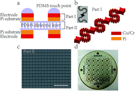
The stretchable parallel plate structure (PPS) sensor unit was designed as a capacitor sandwich structure, as shown in Fig. 1a. For better interconnect and high electrical conductivity between sensor units during stretching and deformation, the sensor electrodes and interconnect wires were designed as a sandwich capacitor structure which has 1.0 μm copper (Cu), 20 nm chromium (Cr) and 5 μm polyimide (PI) on a polydimethylsiloxane (PDMS) substrate with a thickness of 10 μm, named as part I in Fig. 1b. The interconnect wires are the second order serpentine lines with a width of 150 μm for achieving high stretchability and deformability, which could maintain good electrical conductivity during deformation. In order to enhance tactile sensitivity and sensing range for small pressure, the middle dielectric layer of the PPS capacitive sensor was fabricated as micropillars with 200 μm height and 10 μm diameter, named as part II as shown Fig. 1c. The PPS sensor unit is a 4 mm × 4 mm diamond and the distance between sensor units is 8 mm. A 5 × 5 PPS sensor unit array fabricated is shown in Fig. 1d. The fabrication processes of the PPS sensor array include three main steps, making part I and part II, and adhering part I on both sides of part II by PDMS oxygen plasma bonding processing to form a PPS sensor array, and making PDMS semi-balls on top of each sensor for isolation.The circular involution structure (CIS) sensor, as shown in Fig. 2, is consisted of two parallel involution metal/PI electrodes on a flexible PDMS layer with a thickness of 110 μm. Similar to that of PPS sensor, the metal/PI electrodes have a Cr/Cu (20 nm/1.0 μm) layer on a 5 μm thickness PI layer. The two-parallel involution electrodes structure has 50 μm width metal tracks with a 100 μm gap to form a capacitive sensor unit. The gaps between the two electrodes are filled with PDMS dielectric as shown in the cross-sectional view of Fig. 2a. The device could be stretched without being damaged owing to the excellent serpentine interconnect. When a pressure is applied to the circular involution part of the device, the device will bend and the gaps between the two circular involution electrodes change, resulting in a change in capacitance of the device correspondingly. The fabrication processes are simpler than the PPS sensor. The fabrication of the metal/PI electrodes on PDMS layer is similar with that of part I of the PPS devices.
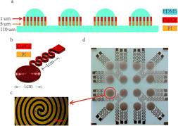 | ||
| Fig. 2 Cross sectional schematic of the CIS sensor (a), formation of the involution electrode (b), overview of the electrode (the scale bar is 300 μm.) (c), fabricated whole 4 × 4 sensors array (d). | ||
Fabrication process of the part I
(1) A silicon wafer with a diameter of 4 inch was cleaned with the standard cleaning process and then coated with polymethylmethacrylate (PMMA) as the sacrificial layer for the sensor devices to be removed from the substrate later. PMMA was spun coated at a speed of 3000 rpm for 40 s and baked at 180 °C for 30 min with the thickness about 1 μm. (2) A pre-prepared PDMS solution was spun coated on the PMMA layer at a speed of 1500 rpm for 10 s and then baked at 80 °C for one hour. A PI layer was then spun coated on the PDMS at a speed of 3500 rpm for 40 s and baked with a programmed temperature ramping: 110 °C for 2 min, 150 °C for 20 min, 200 °C for 30 min, and then cool down naturally. Cr/Cu electrodes were formed on the PI layer by photolithography and lift-off process. (4) Finally, the area of PI layer without being covered by the metal electrodes was removed by oxygen plasma etching.Fabrication process of the part II
A Si mould with grooves of cylindrical array was fabricated by deep reactive ion etching (Plasmalab System 100, Oxford) with a depth of 30 μm. The mould was immersed into a release agent which is a mixture of 5% ethanol and cleanser essence for 3 h to increase the surface hydrophobicity for better PDMS structure release. A pre-prepared PDMS solution was spun coated on the mould at a speed of 2500 rpm for 10 s, then pressed PDMS for half an hour, and then baked at 90 °C for one hour without removing the mould and stress. Finally, the PDMS micropillars dielectric layer was peeled off from the silicon mould.Results and discussion
Performance of the devices
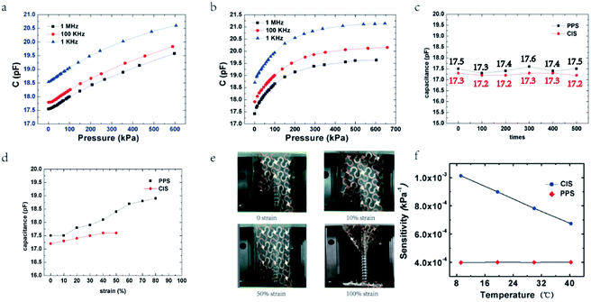
Fig. 3a and b show the capacitance as a function of applied pressure for both types of the capacitive sensors. Since capacitance of a device with dielectric layer typically depends on the measurement frequency, we characterized the performance and sensitivity of each sensing unit at different frequencies. For the PPS sensor, the capacitance increases with pressure applied nearly linearly, showing a relatively good linearity below 300 kPa. The increase rate of capacitance with pressure becomes smaller and tends to saturate above that. The linearity and pressure sensing range could meet the requests for the targeted pressure sensor applications. On the other hand, the CIS sensor initially increases with pressure linearly at pressures below 100 kPa, and slows down as the pressure is increased further above 300 kPa. The nonlinearity performance of the CIS sensor for the full measuring range may restrict its application. At different frequencies, capacitance increases with pressure with similar characteristics which indicate that the PPS sensors have a broader pressure sensing range than that of CIS sensors, and operation frequency needs to be fixed for specific applications. Both PPS and CIS sensors were stretched for 500 times under 80% and 40 % strain repeatedly without obvious capacitance change were observed (Fig. 3c). The capacitance of the PPS sensor increases from 17.5 pF to 18.7 pF with the applied strain from 0 to 80% (Fig. 3d), which results from the decrease of the distance between two electrodes. But for CIS sensor, the capacitance increases only from 17.2 pF to 17.6 pF under 40% stretch. During 0–40% range, the capacitance changes of the PPS sensors are two times higher than those of CIS ones. This is because the capacitance changes due to the distance decrease between two electrodes perpendicular to the direction of stretching would be offset partially by the distance increase parallel to the direction of stretching, which results in the slightly increase of the capacitance. Beyond the deformation limits (55% for CIS sensor, 90% for PPS sensor), the devices fail with either broken metal electrode lines or complete break of the device as shown in Fig. 3e. The excellent stretchability of the devices is attributed to the serpentine and involution structures of the sensors which are sufficient for most of applications. The response time of the sensors array is restricted by microchip AD7746 based testing circuit (Fig. S1†) which has the highest sampling frequency of 90 Hz. The change of the capacitance could be recorded between two sampling process, which indicated the response time of the sensors was at least 11 ms. The sensitivity of a pressure sensor can be defined as:| S = ΔC/(C × ΔP) | (1) |
 | (2) |
Distinguishing different objects
Considering that the PPS sensor has better linearity and temperature stability, a stretchable tactile sensor with 3 × 3 PPS capacitive units was developed as sensing fingers for robotic application. The mechanical arm (Epson C4-601) with robotic fingers has no sensors integrated. The stretchable tactile sensor was glued on one of the three fingers of mechanical arm for grasping experiments (Fig. 4a). Owing to its stretchability and flexibility, the PPS capacitive units could attach to the finger and cover the curved surface of the mechanical arm perfectly. From grasping experiments, as shown in Fig. 4b, it is clear that the capacitances of all the PPS sensor units change when the robotic fingers grasp an apple (Fig. 4c) or an orange (Fig. 4d). The middle pixel capacitance has the biggest change because the middle pixel has stronger contact with the fruit than other pixels do. However, the changes of capacitances of the 3 × 3 PPS sensor array for apple grasping are different from those for orange grasping. The reason is that apple has different hardness and surface morphology from those of orange. Apple is harder and has a curved surface from which the change of the middle pixel capacitance is much larger than those of other pixels. Orange is softer, therefore the change of the middle pixel capacitance is slightly larger than that of others pixels. It can be concluded that the tactile sensor could sense object's hardness by analysis of capacitance changes based on this principle. A number of testing results showed that the tactile sensors indeed can distinguish apples from oranges with accuracy over 90%.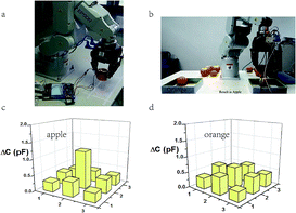 | ||
| Fig. 4 Robotic finger attached tactile sensor with a 3 × 3 PPS sensors array can distinguish apple (a) and orange (b). Capacitance changes of apple (c) and orange (d) by grasping test. | ||
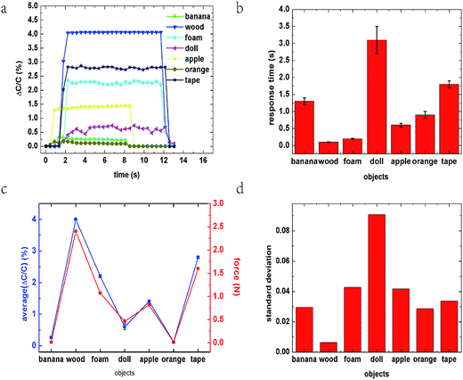
The tactile sensor with one PPS capacitive unit was also designed and fitted to one of the robotic fingers to “feel” hardness and weight of objects by grasping test and the effective contact area is defined as the single capacitive unit with the dimension of 4 mm × 4 mm. Several objects were utilized for objects distinguishing experiment, including a wood block (∼512.2 g), a tape (∼305.4 g), a block of foam (∼280.1 g), an apple (∼220.3 g), a doll (∼173.5 g), a banana (∼130.7 g) and an orange (∼105.8 g). Capacitance change of the PPS sensor is shown in Fig. 5a for the whole grasping process from picking the object up to dropping it down. There are three characteristic variables: response time, average capacitance change and its deviation, which can be used to distinguish different objects. The response time is the time from the initial contacting between the object and the robot hand, until the object is firmly grasped. Several test were conducted and the average response time are shown in Fig. 5b. For example, wood typically has a response time only about 0.1 s, while dolls have a 3.0 s response time. For objects with stiffer and no elastic surface, it is easier to achieve the firm contact with the robot finger to reach the threshold force for picking up the object; while for softer objects, such as banana and doll, the robot finger needs more time to obtain the threshold force before picking up the object. Based on this, the hardness of different tested objects in Fig. 5b could be sensed and arranged in the following order: wood > foam > apple > orange > banana > tape > doll. Fig. 5c shows the average capacitance change of the PPS sensor during holding process for different objects, which reflects the weight of different objects. The force applied on the objects also shows the similar trend. The deviation of average capacitance change represents the surface elasticity by analysing the output stability during holding process (Fig. 5d). For example, the standard deviation for a doll is 0.09067, larger than those of fruits (0.02964 for banana, 0.04182 for apple and 0.02868 for orange) and wood (0.00636). This is because that deformation is severer for elastic and softer objects on holding, the robot finger needs to adjust the pressure continuously to avoid the object dropping down. In conclusion, each object has different response time, average capacitance change and its deviation which corresponding to the grasped objects hardness, elasticity and weight repectively. The results demonstrated the potential applications of the tactile sensors for separating objects.
Conclusions
Two flexible and stretchable capacitive types of pressure sensors have been developed with vertical and parallel serpentine electrodes using PDMS as the elastic dielectric layer as well as the support layer. With the assistance of serpentine structure, the PPS and CIS sensors can withstand deformations up to 90% and 55%, respectively. The PPS sensors have a near-zero temperature coefficient, while the CIS sensors have a small linear temperature coefficient, which could be attributed to their structural designs. Compared with those of the PPS sensors, the CIS sensors show more convenience in the fabrication process and better stretching stability within the working range. A 3 × 3 PPS unit array was glued on the robotic finger as a tactile sensor to distinguish objects with different morphologies and stiffness by analysing features of the output signals, including relative capacitance change, response time and stability. However, the sensor array with higher resolution could be developed in the future for more accurate detection, which would be beneficial for more practical application scenarios. The results indicated the potential application of tactile sensor and its array in surgical robot, which could be beneficial for distinguishing tissue types, such as muscle, fat, bone, or blood vessels, with different stiffness and elasticity by touching and grasping.Conflicts of interest
There are no interest conflicts to declare.Acknowledgements
This work was supported by the following programs: National Key Research and Development Plan (No. 2016YFB1001203), National Natural Science Foundation of China (Nos. U1613202, U1609210, 61376118, and 31371001), and Fundamental Research Funds for Central Universities (2016XZZX001-005), Zhejiang science and technology plan (No. 2016C31061).Notes and references
- J. Kim, M. Lee, H. J. Shim, R. Ghaffari, H. R. Cho, D. Son, Y. H. Jung, M. Soh, C. Choi, S. Jung, K. Chu, D. Jeon, S. T. Lee, J. H. Kim, S. H. Choi, T. Hyeon and D. H. Kim, Nat. Commun., 2014, 5, 5747 CrossRef CAS PubMed.
- S. Xu, Y. Zhang, L. Jia, K. E. Mathewson, K.-I. Jang, J. Kim, H. Fu, X. Huang, P. Chava and R. Wang, Science, 2014, 344, 70–74 CrossRef CAS PubMed.
- V. J. Lumelsky, M. S. Shur and S. Wagner, IEEE Sens. J., 2001, 1, 41–51 CrossRef CAS.
- W. Honda, S. Harada, T. Arie, S. Akita and K. Takei, Adv. Funct. Mater., 2014, 24, 3299–3304 CrossRef CAS.
- M. K. Choi, J. Yang, K. Kang, D. C. Kim, C. Choi, C. Park, S. J. Kim, S. I. Chae, T. H. Kim, J. H. Kim, T. Hyeon and D. H. Kim, Nat. Commun., 2015, 6, 7149 CrossRef CAS PubMed.
- L. Y. Chen, B. C. Tee, A. L. Chortos, G. Schwartz, V. Tse, D. J. Lipomi, H. S. Wong, M. V. McConnell and Z. Bao, Nat. Commun., 2014, 5, 5028 CrossRef CAS PubMed.
- Y. Zang, F. Zhang, C.-a. Di and D. Zhu, Mater. Horiz., 2015, 2, 140–156 RSC.
- J. Tegin and J. Wikander, Industrial Robot: An International Journal, 2005, 32, 64–70 CrossRef.
- G. Canavese, S. Stassi, C. Fallauto, S. Corbellini, V. Cauda, V. Camarchia, M. Pirola and C. F. Pirri, Sens. Actuators, A, 2014, 208, 1–9 CrossRef CAS.
- Q. Zhong, J. Zhong, X. Cheng, X. Yao, B. Wang, W. Li, N. Wu, K. Liu, B. Hu and J. Zhou, Adv. Mater., 2015, 27, 7130–7136 CrossRef CAS PubMed.
- R. C. Webb, Y. Ma, S. Krishnan, Y. Li, S. Yoon, X. Guo, X. Feng, Y. Shi, M. Seidel, N. H. Cho, J. Kurniawan, J. Ahad, N. Sheth, J. Kim, J. G. Taylor Vi, T. Darlington, K. Chang, W. Huang, J. Ayers, A. Gruebele, R. M. Pielak, M. J. Slepian, Y. Huang, A. M. Gorbach and J. A. Rogers, Sci. Adv., 2015, 1, e1500701 Search PubMed.
- D. H. Kim, N. Lu, R. Ghaffari, Y. S. Kim, S. P. Lee, L. Xu, J. Wu, R. H. Kim, J. Song, Z. Liu, J. Viventi, B. de Graff, B. Elolampi, M. Mansour, M. J. Slepian, S. Hwang, J. D. Moss, S. M. Won, Y. Huang, B. Litt and J. A. Rogers, Nat. Mater., 2011, 10, 316–323 CrossRef CAS PubMed.
- A. Blau, A. Murr, S. Wolff, E. Sernagor, P. Medini, G. Iurilli, C. Ziegler and F. Benfenati, Biomaterials, 2011, 32, 1778–1786 CrossRef CAS PubMed.
- S. Gong, W. Schwalb, Y. Wang, Y. Chen, Y. Tang, J. Si, B. Shirinzadeh and W. Cheng, Nat. Commun., 2014, 5, 3132 Search PubMed.
- L. Pan, A. Chortos, G. Yu, Y. Wang, S. Isaacson, R. Allen, Y. Shi, R. Dauskardt and Z. Bao, Nat. Commun., 2014, 5, 3002 Search PubMed.
- N. T. Selvan, S. B. Eshwaran, A. Das, K. W. Stöckelhuber, S. Wießner, P. Pötschke, G. B. Nando, A. I. Chervanyov and G. Heinrich, Sens. Actuators, A, 2016, 239, 102–113 CrossRef CAS.
- W. Wu, X. Wen and Z. L. Wang, Science, 2013, 340, 952–957 CrossRef CAS PubMed.
- K.-I. Park, J. H. Son, G.-T. Hwang, C. K. Jeong, J. Ryu, M. Koo, I. Choi, S. H. Lee, M. Byun, Z. L. Wang and K. J. Lee, Adv. Mater., 2014, 26, 2514–2520 CrossRef CAS PubMed.
- B. Li, A. K. Fontecchio and Y. Visell, Appl. Phys. Lett., 2016, 108, 013502 CrossRef.
- E. Cagatay, P. Kohler, P. Lugli and A. Abdellah, IEEE Sens. J., 2015, 15, 3225–3233 CrossRef.
- S. C. Mannsfeld, B. C. Tee, R. M. Stoltenberg, C. V. Chen, S. Barman, B. V. Muir, A. N. Sokolov, C. Reese and Z. Bao, Nat. Mater., 2010, 9, 859–864 CrossRef CAS PubMed.
Footnote |
| † Electronic supplementary information (ESI) available. See DOI: 10.1039/c7ra08605a |
| This journal is © The Royal Society of Chemistry 2017 |

