
 Open Access Article
 This Open Access Article is licensed under a
 Creative Commons Attribution 3.0 Unported Licence
Pyrolysis gas as a carbon source for biogas production via anaerobic digestion
Yeqing Lia,
Dongfang Sua,
Sen Luoa,
Hao Jianga,
Mingyu Qianab,
Hongjun Zhoua,
Jason Streetc,
Yan Luod and
Quan Xu *a
*a
aState Key Laboratory of Heavy Oil Processing, Beijing Key Laboratory of Biogas Upgrading Utilization, Institute of New Energy, China University of Petroleum Beijing (CUPB), Beijing, 102249, P. R. China. E-mail: xuquan@cup.edu.cn
bFaculty of Agricultural and Environmental Sciences, University of Rostock, Justus-von-Liebig-Weg 6, 18059 Rostock, Germany
cDepartment of Sustainable Bioproducts, Mississippi State University, Mississippi State 39762, USA
dDepartment of Chemical Engineering, West Virginia University, USA
First published on 29th August 2017
Abstract
Carbon is an important resource for anaerobes to enhance biogas production. In this study, the possibility of using simulated pyrolysis gas (SPG) as a carbon source for biogas production was investigated. The effects of stirring speed (SS), gas holding time (GHT), and H2 addition on biomethanation of SPG were evaluated. The diversity and structure of microbial communities were also analyzed under an illumina MiSeq platform. Results indicated that at a GHT of 14 h and an SS at 400 rpm, SPG with up to 64.7% CH4 could be bio-upgraded to biogas. Gas–liquid mass transfer is the limitation for SPG biomethanation. For the first time, it has been noticed that the addition of H2 can bioupgrade SPG to high quality biogas (with 91.1% CH4). Methanobacterium was considered as a key factor in all reactors. This study provides an idea and alternative way to convert lignocellulosic biomass and solid organic waste into energy (e.g., pyrolysis was used as a pretreatment to produce pyrolysis gas from biomass, and then, pyrolysis gas was bioupgraded to higher quality biogas via anaerobic digestion).
1. Introduction
The global trend of energy use is moving towards sustainable development, and the waste-to-energy (WTE) concept is being highly promoted as a part of this effort.1,2 Nowadays, biomass is being utilized to generate renewable energy in many countries of the world.3,4 Biomass covers about 50 exajoule per year of the total primary energy demand of the world.5 Biomass resources have been paid increasing attention because of their renewability and biodegradability.6 In particular, the composition and energy utilization of biomass energy are very similar to those of fossil energy. Thus, it has the largest potential to substitute for conventional energy. Biomass materials have been used as structural materials or common materials from ancient times because their major components are natural polymers such as lignin, cellulose, starch, chitin, and protein, which guarantee enough strength and stability.7 According to China's unique energy structure and abundant biomass resources, the generation of high quality bio-gas by gasification of biomass becomes a research emphasis.Pyrolysis process has a potential to produce pyrolysis gas (major components are carbon monoxide (CO), hydrogen (H2), and carbon dioxide (CO2), and minor components are other gases, e.g., methane (CH4) and some volatile impurities) from biomass (e.g., lignocellulosic biomass, industrial and municipal solid waste, lignite, and digestate).8–11 One advantage of this process is that most of the organic components, especially the relatively dry and slowly biodegradable biomass (e.g., wood and woodchips) that are not suitable or effective for anaerobic digestion (AD) process, would be converted to pyrolysis gas. However, CO is a toxic gas for many organisms due to its high affinity for metal-containing enzymes. The presence of high concentrations of CO is a restriction in the utilization of pyrolysis gas in some applications.7,11 Moreover, low volumetric energy density (usually less than 13 MJ m−3) is a limitation for pyrolysis gas when used as a fuel gas.8,12 To convert the pyrolysis gas into high quality gas, a methanation process is necessary. Traditional catalytic methanation requires high pressure and temperature (230–700 °C) and a metal catalyst, which involves high cost and energy consumption. A potentially more economical alternative is the utilization of a biological system to convert biomass pyrolysis gases to biomethane. Several trials have been reported to biologically convert CO, H2, and CO2 to biomethane via biomethanation system.13 Wang et al.14 reported that co-digestion of coke oven gas (COG) (92% H2 and 8% CO) and sewage sludge could achieve in situ biogas upgradation and simultaneous COG biomethanation. Youngsukkasem et al.15 found that using syngas and organic substances as feedstock for AD in a repeated batch mode, a good performance without any negative effect was observed. The conversion of H2 and CO2 to CH4 is a common biological reaction occurring in the anaerobic digestion reactor. Only a small number of microorganisms (e.g., Methanobacterium thermoautotrophicum, Methanosarcina barkeri, Methanothermobacter thermautotrophicus, and Methanosaeta thermophila) can achieve CO biomethanation.13,16,17 Since the solubility of H2 is 0.00016 g per 100 g of water above 1 atm and the solubility of CO is 0.0028 g per 100 g of water above 1 atm, anaerobic digestion of pyrolysis gas is typically limited by the gas–liquid mass transfer rate.13 From the view of thermodynamics, the reaction CO + H2 → CH4 is exothermic. However, in the biomethanation reaction, no significant temperature changes were found due to the low conversion rate of biocatalysis as compared to traditional catalytic methanation. Actually, in the anaerobic digestion process, the system needs to be maintained at a constant temperature of 37 °C to keep the microorganisms at a higher biocatalytic activity. The constant temperature is provided by an extra heat source. Thus, development of a suitable reactor and optimization of operating conditions are necessary. Moreover, a low cost and long-term AD operation is needed to industrialize the pyrolysis gas biomethanation technology.
Based on the abovementioned considerations, in this study, biomethanation was achieved in long-term AD tests where SPG was utilized as a carbon source for biogas production. AD can increase the LVC of SPG from 12.9 to 23.2 MJ m−3, and Methanobacterium was dominant in the whole process. The conversion rates of CO and H2 were 96.6% and 99.2%, respectively, which could effectively enhance gas production. The objectives of this study were as follows: (1) to investigate the effect of stirring intensity (SS), gas holding time (GHT), and H2 addition on biomethanation of pyrolysis gas and (2) to evaluate the system stability using pyrolysis gas as a carbon source in long-term anaerobic digestion operation.
2. Experimental
2.1. Experiment setup
Herein, three 1.69 L continuously stirred tank reactors (named R1–R3) with a working volume of 1.2 L were used. Non acclimated inoculum was obtained from the mixed effluent of anaerobic reactors treating various organic wastes (e.g., chicken manure, dairy manure, corn stover and food waste) in our laboratory. Before utilization, the residual solid matter in effluent was removed using a sieve. Then, liquid inoculum was pre-incubated at a constant temperature (37 °C) incubator shaker (ZWYR-D2402, China) for degassing. The shaking speed was 120 rpm. After two weeks of pre-incubation, no gas was detected from inoculum. Then, the degassed inoculum was transferred to three reactors. The total solids (TS) and volatile solids (VS) of inoculum were 2.33 ± 0.02% FM and 1.03 ± 0.00% FM, respectively. To ensure an oxygen-free environment, the headspace of each reactor was purged with nitrogen gas for 2 min. The digestion temperature was 37 °C. Simulated pyrolysis gas (H2![[thin space (1/6-em)]](https://www.rsc.org/images/entities/char_2009.gif) :CO:CH4:CO2 = 35:30:15:20 on volume basis) was manually added to the reactors by a 100 mL syringe. Once added, pyrolysis gas was kept in the reactors for 24 h or 48 h depending on the experiment design (Table 1). To bioupgrade the generated gas from the reactor R2, pure hydrogen and generated gas from R2 were added to the reactor R3. To investigate the process stability of using simulated pyrolysis gas as the only substrate, no additional carbon source was added to this system. During steady-states, the liquid samples were obtained from R1–R3 for high-throughput 16S rRNA sequencing and analysis. Specific experiment design is shown in Table 1.
:CO:CH4:CO2 = 35:30:15:20 on volume basis) was manually added to the reactors by a 100 mL syringe. Once added, pyrolysis gas was kept in the reactors for 24 h or 48 h depending on the experiment design (Table 1). To bioupgrade the generated gas from the reactor R2, pure hydrogen and generated gas from R2 were added to the reactor R3. To investigate the process stability of using simulated pyrolysis gas as the only substrate, no additional carbon source was added to this system. During steady-states, the liquid samples were obtained from R1–R3 for high-throughput 16S rRNA sequencing and analysis. Specific experiment design is shown in Table 1.
| Reactor R1 | Reactor R2 | Reactor R3 | ||||
|---|---|---|---|---|---|---|
| Phase 1 (1–43 days) | Phase 2 (44–59 days) | Phase 3 (60–91 days)a | Phase 1 (1–86 days) | Phase 1 (1–21 days) | Phase 2 (22–63 days) | |
| a Gas composition (H2:CO:CH4:CO2 = 4.5:1.5:0.75:1, on volume basis).b Day 11–13, the gas holding time was adjusted to 24 h.c Calculations were obtained based on 10 measurements during steady states. |
||||||
| Gas flow rate (mL d−1) | 163 ± 7 | 325 ± 7 | 505 ± 11 | 325 ± 7 | 270 ± 39c | 363 ± 33c |
| Initial CO partial pressure (atm) | 0.20 | 0.20 | 0.21 | 0.20 | NA | NA |
| Initial H2 partial pressure (atm) | 0.23 | 0.23 | 0.62 | 0.23 | NA | NA |
| H2/CO ratio | 1.17 | 1.17 | 3.00 | 1.17 | NA | NA |
| Gas holding time (h) | 48b | 24 | 24 | 24 | 24 | 24 |
| Stirring speed (rpm) | 120 | 120 | 120 | 400 | 400 | 400 |
2.2. Cross-linking process
TS and VS were determined according to the standard methods.18 Gas samples were obtained every one or two days to detect the composition. A gas chromatograph (FULI 9790II, China) equipped with a thermal conductivity detector (TCD) was used with helium as the carrier gas. The temperatures of the injector, oven, and detector were 150, 130, and 160 °C, respectively. The corrected CH4, CO, CO2, and H2 content of the produced gas (i.e. CH4corr, COcorr, CO4corr, and H2corr) was calculated according to Li et al.19 Biogas production of all reactors was measured daily by a 100 mL syringe. The pH was measured using a pH meter (SARTORIUS PB-10). The volatile fatty acids (VFA) and total inorganic carbon (TIC) were measured using a Mettler Toledo T70. Then, 7 mL sample was taken using a pipette (3.5 mL twice) into the titration beaker, and water was added to 40 mL scale line; then, the titration beaker was put on the titrator, the titration was started to adjust the pH of the sample to 5.0, 4.4, 4.3, and 4.0 with 0.025 mol L−1 H2SO4, and the volume of H2SO4 used for each pH value was obtained. The VFA and VFA/TIC were then calculated according to Nie et al.20Lower calorific values (LCV, MJ m−3) of the simulated pyrolysis gas and generated gas were determined according to Li et al.8
During steady-states, the liquid samples were obtained in phase 1 and 2 of the reactor R1 (named R1P1 and R1P2), phase 1 of the reactor R2 (named R2P1), and phase 1 of the reactor R3 (named R3P1) for sequencing using an Illumina MiSeq platform at Majorbio Company (Shanghai, China). Inoculum was also analyzed as a control. Microbial DNA was extracted from samples using the E.Z.N.A.®AxyPrepDNA Kit (Omega Bio-tek, Norcross, GA, U.S.) according to manufacturer's protocols. The V4–V5 region of the bacteria 16S ribosomal RNA gene was amplified by PCR (95 °C for 2 min, followed by 25 cycles at 95 °C for 30 s, 55 °C for 30 s, and 72 °C for 30 s and a final extension at 72 °C for 5 min) using primers Arch519F and Arch915R. PCR reactions were performed in triplicate 20 μL mixture containing 4 μL of 5× FastPfu Buffer, 2 μL of 2.5 mM dNTPs, 0.8 μL of each primer (5 μM), 0.4 μL of FastPfu Polymerase, and 10 ng of template DNA.
Operational taxonomic units (OTUs) were clustered with 97% similarity cut-off using UPARSE (version 7.1 http://drive5.com/uparse/), and chimeric sequences were identified and removed using UCHIME. The taxonomy of each 16S rRNA gene sequence was analysed by RDP Classifier (http://rdp.cme.msu.edu/) against the silva (SSU115) 16S rRNA database using the confidence threshold of 70%. Specific Illumina MiSeq sequencing procedures and processing of sequencing data can be found.
3. Results and discussion
3.1. Effect of the gas holding time (GHT)
The time course of biogas production, biogas composition, pH, VFA concentrations, and VFA/TIC ratio are shown in Fig. 1–3. Table 1 summarizes the reactor performance during steady-states of each operation condition. Reactor R1 was operated at a low stirring speed (SS) of 120 rpm. Biogas production increased from 60 ± 5 mL d−1 to 114 ± 24 mL d−1 with the gas holding time (GHT) decreasing from 48 h to 24 h. The corresponding CH4 content was decreased from 62.2 ± 1.3% to 49.9 ± 1.3%. The CO and H2 conversion efficiency were 93.3 ± 1.2% and 98.5 ± 0.5% in phase 1 and 91.5 ± 2.3% and 85.1 ± 3.9% in phase 2, respectively. Change in the GHT can influence the CH4 content, and CO and H2 conversion efficiency; this indicates that the contact time of gas and liquid is an important parameter for SPG biomethanation. For reactor R1, on increasing the injected gas flow from 325 mL d−1 to 505 mL d−1 (325 mL SPG + 180 mL H2), the biogas production increased. However, high percentages of H2 and CO were also determined in generated biogas (phase 3), indicating that the biomethanation efficiency in this operation was low. The corresponding H2 and CO conversion efficiency were only 84.0 ± 3.6% and 77.5 ± 2.4%, respectively. The methane content in phase 3 of R1 was also low as compared to that in phase 1 of R1.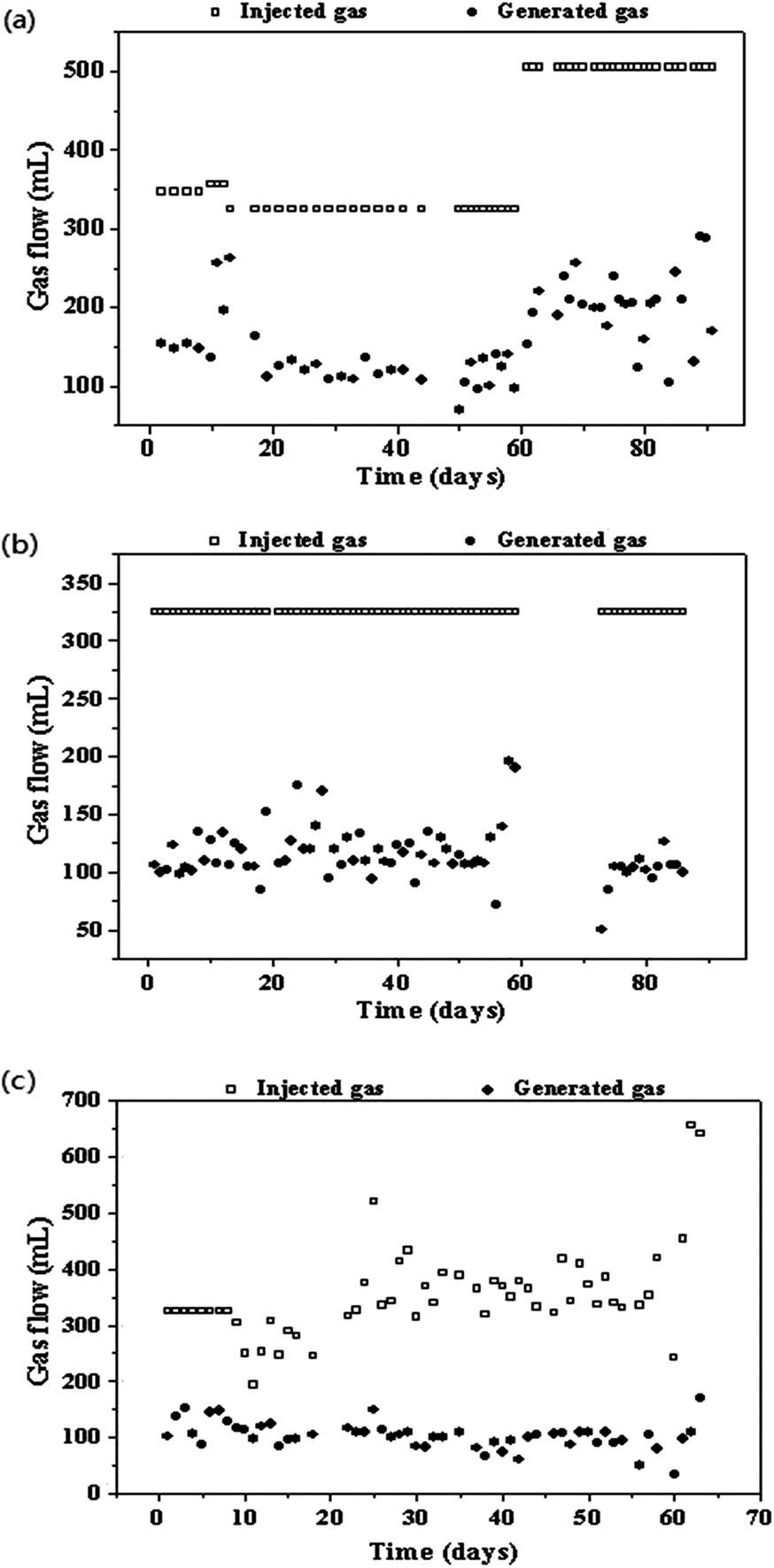 | ||
| Fig. 1 Profiles of the gas injection and generation rate (a, b, and c representing the reactor R1, R2, and R3, respectively). | ||
3.2. Effect of the stirring speed (SS)
For the reactor R2, H2 and CO were not detected in the generated gas at SS of 400 rpm and GHT of 24 h; this indicated that they were efficiently utilized by the microorganisms in the reactor. Methane content was 64.7 ± 0.8% in R2 when the SS was adjusted to 400 rpm (Table 1 and Fig. 2), indicating that SS was a higher influence factor on biomethanation of SPG as compared to GHT. Similar results were found by Luo and Angelidaki21 indicating that increase in the stirring speed of the reactor from 150 to 300 rpm could increase H2 consumption rate. As reported by Guiot et al.,13 gaseous feedstock is difficult to be captured by the microbes in the liquid phase. Further study should be focussed on the conversion efficiency of pyrolysis gas biomethanation and minimization of the gas–liquid mass transfer limitation. From 60 to 72 days, reactor R2 was only maintained at 37 °C without the input of SPG and output of generated gas due to the absence of researcher. On 73rd day, this reactor was recovered with feeding SPG, and it performed well in the next days.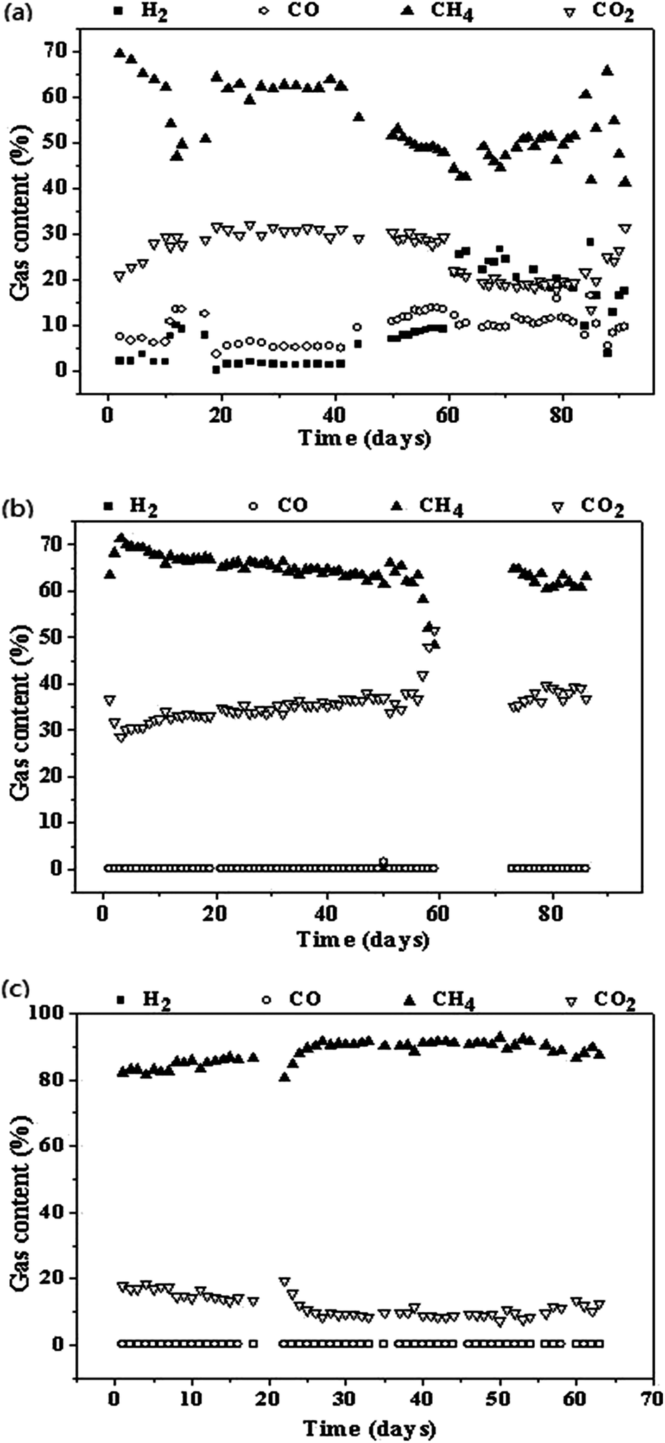 | ||
| Fig. 2 Profiles of biogas composition (a, b, and c representing the reactor R1, R2, and R3, respectively). | ||
3.3. Effect of hydrogen addition
In reactor R3, injected gas was composed by generated gas from reactor R2 (CH4 content was 64.7 ± 0.8%) and additional H2. The addition of H2 reached 116 ± 11 mL and 241 ± 33 mL per day in phase 1 and phase 2 of R3, respectively (Table 1). The corresponding CH4 contents were 85.7 ± 1.0% and 91.1 ± 1.0%, respectively, which indicated that addition of H2 could largely increase the CH4 content (Fig. 2). Luo and Angelidaki22 found that the addition of H2 could achieve in situ biogas upgradation (methane content was from 78.4% to 90.2%) when using mixture of cattle manure and whey as feedstock. In this study, SPG was used as a carbon source. Moreover, through the addition of H2, SPG biomethanation was achieved. H2 can be generated from electrolysis of water using extra electricity or unstable wind electricity, or water photolysis or methanol decomposition. The H2-assisted bioupgradation has several advantages, such as no CH4 loss, low investment cost for additional equipment, and storage of excess electricity as methane, as compared to CO2-air strippers or autogenerative high pressure digestion (AHPD) method.3.4. Calculation of mass balance
Due to the SPG containing 15% of CH4 as a feed gas in the experiments, the mass balance discussion is necessity. Taking R1P1 for example, the SPG addition is 163 mL with 15% CH4 (24.5 mL CH4 added), and the biogas production is 60 mL with 62.2% CH4 (37.3 mL CH4 produced); thus, the pure CH4 production is 12.8 mL. Similar calculation results for all the other phases are shown in Table 1. The results further inferred that CO, CO2, and H2 were converted to methane by the anaerobic microbes.3.5. Evaluation of the energy output
Although pyrolysis gas can be directly used as fuel gas, the volumetric energy density of pyrolysis gas is only about 50% of biogas. The conversion of pyrolysis gas to CH4 is an important step to meet the increasing demand for natural gas. After SPG biomethanation, the energy output results are shown in Table 1. According to the lower calorific value (LCV) calculation equation,8 the lower calorific value of injected gas (LCVin) for R1 and R2 was determined to be 12.2–12.9 MJ m−3. After biomethanation process, the lower calorific value of generated gas (LCVout) ranged from 20.4 to 23.2 MJ m−3. For reactor R3, LCVout was 30.7–32.7 MJ m−3 after the addition of H2. Herein, two-step approach (SPG biomethanation and H2 addition) could be a minder and alternative way to bioupgrade pyrolysis gas into high quality biogas and convert toxic gas CO to CH4.3.6. Process stability
During the long-term anaerobic digestion tests, using SPG as a carbon source, pH value was around 8.0 for R1 and R2 and 8.3–8.6 for R3. The pH value increased to higher than 8.0 in reactor R3 (Table 1 and Fig. 3) as H2 addition was associated with the consumption of CO2 in the reactors. Similar result was obtained by Luo and Angelidaki,22,23 where manure alone was used as a substrate and pH value in reactor increased to higher than 8.0. In this study, no significant inhibition was found although the pH value was not in the optimum range of 7.2–7.8. The VFA concentration showed an increasing trend with time and was determined to be 770–1058 mg L−1 for R1, 913 mg L−1 for R2, and 463–1727 mg L−1 for R3. The VFA/TIC ratios of R1–R3 were lower than 0.4, which were in a normal range.19 Generally, anaerobic reactors can perform well using SPG as a carbon source when the pH in the reactors remains above 8.0.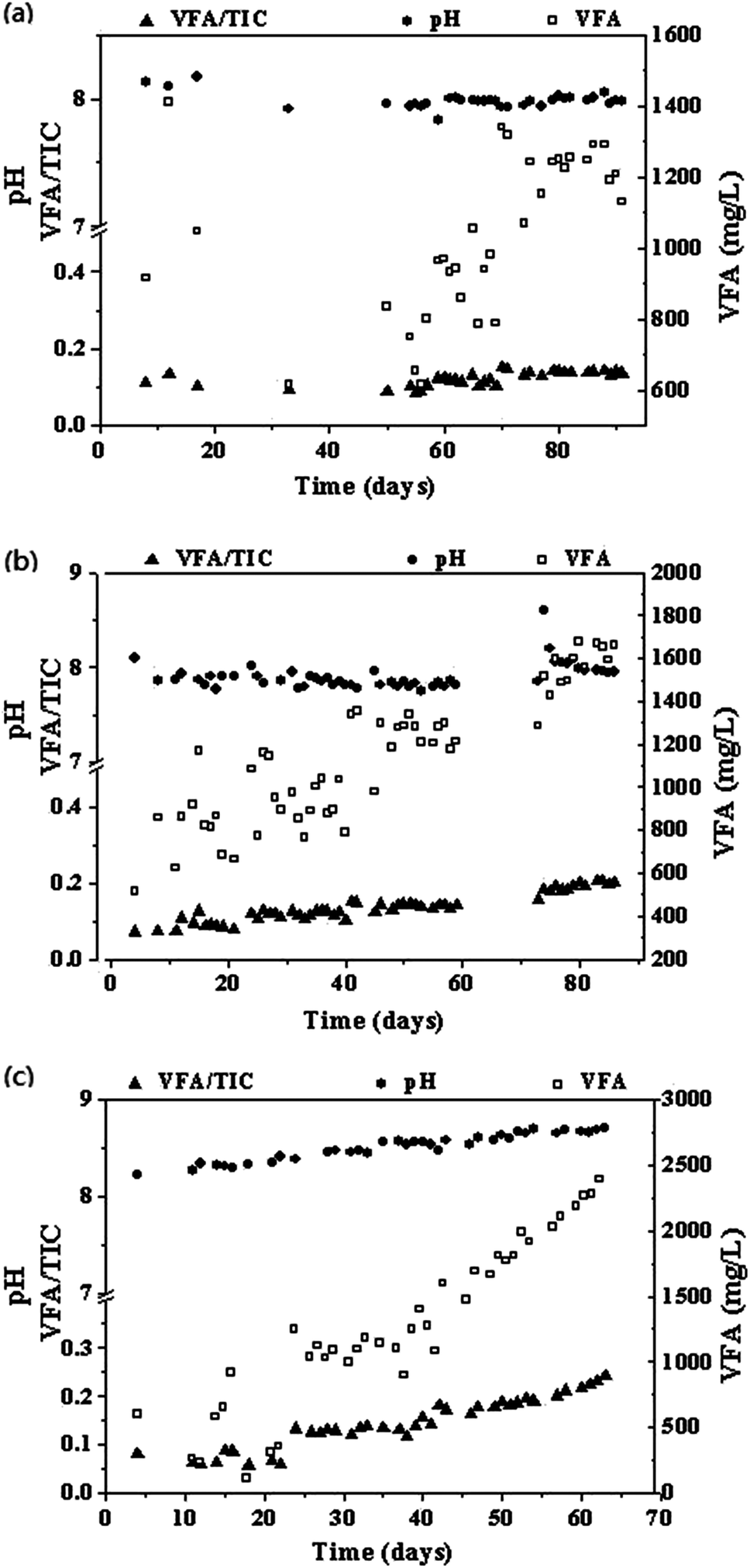 | ||
| Fig. 3 Profiles of pH, VFA, and TIC (a, b, and c represent reactor R1, R2, and R3, respectively). | ||
3.7. Microbial community analysis
Reaction equations of CO/synthesis gas biocatalysis are summarized in Table 2. CO and H2 from synthesis gas can be converted to CH4 in two ways: direct and indirect conversions. In the first reaction, CH4 was formed directly via conversion of CO, H2, and CO2 by microorganisms.22 In the second reaction, intermediate products (e.g., formic acid, methanol, and acetic acid) were formed, and then, CH4 was observed by degradation of the intermediate products.24–26| Product | Reaction | ΔG0, kJ mol−1 | References |
|---|---|---|---|
| Formic acid | CO + H2O → HCOOH | −16 | 10 |
| Acetic acid | 4CO + 2H2O → CH3COOH + 2CO2 | −43.6 | 12 |
| 4H2 + 2CO2 → CH3COOH + 2H2O | −55.1 | 16 | |
| 2CO + 2H2 → CH3COOH | −67 | 10 | |
| Butyric acid | 10CO + 4H2O → CH3CH2CH2COOH + 6CO2 | −44 | 18 |
| 4CO + 6H2 → CH3CH2CH2COOH + 2H2O | −80 | 18 | |
| Methanol | CO + 2H2 → CH3OH + H2O | −39 | 10 |
| Ethanol | 6CO + 3H2O → CH3CH2OH + 4CO2 | −37 | 18 |
| 2CO + 4H2 → CH3CH2OH + H2O | −72 | 19 | |
| n-Butanol | 12CO + 5H2O → CH3(CH2)3OH + 8CO2 | −40 | 19 |
| 4CO + 8H2 → CH3(CH2)3OH + H2O | −81 | 19 | |
| Hydrogen | CO + H2O → H2 + CO2 | −20 | 7 |
| Methane (direct) | 4CO + 2H2O → CH4 + 3CO2 | −52.6 | 12 |
| 4H2 + CO2 → CH4 + 3CO2 | −130.7 | 20 | |
| CO + 3H2 → CH4 + H2O | −150 | 10 | |
| Methane (indirect) | CH3COOH → CH4 + CO2 | −28 | 27 |
| 4CH3OH → 3CH4 + CO2 + 2H2O | −103 | 27 | |
| 4HCOOH → CH4 + 3CO2 + 2H2O | −127 | 27 |
Fig. 4 shows the rarefaction curves based on an operational taxonomic units (OTU) definition of 97% sequence similarity. New OTUs continue to appear even after sampling 2000 sequences for archaea. However, the coverage values for archaea (>99%) indicated that most common OTUs were detected (Fig. 5). The Shannon diversity, CHAO1, and ACE richness index provides not only species richness but also the evenness of the species among all the species in the community. In the current work, inoculum had higher diversity and richness as compared to other samples. This may be because inoculum was obtained from the mixed effluent of anaerobic digesters treating various organic wastes, and samples from reactors R1–R3 were only fed with SPG.
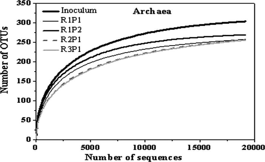 | ||
| Fig. 4 Rarefaction curves based on the sequencing of archaea communities. The OTUs were defined by the 0.03 distance. | ||
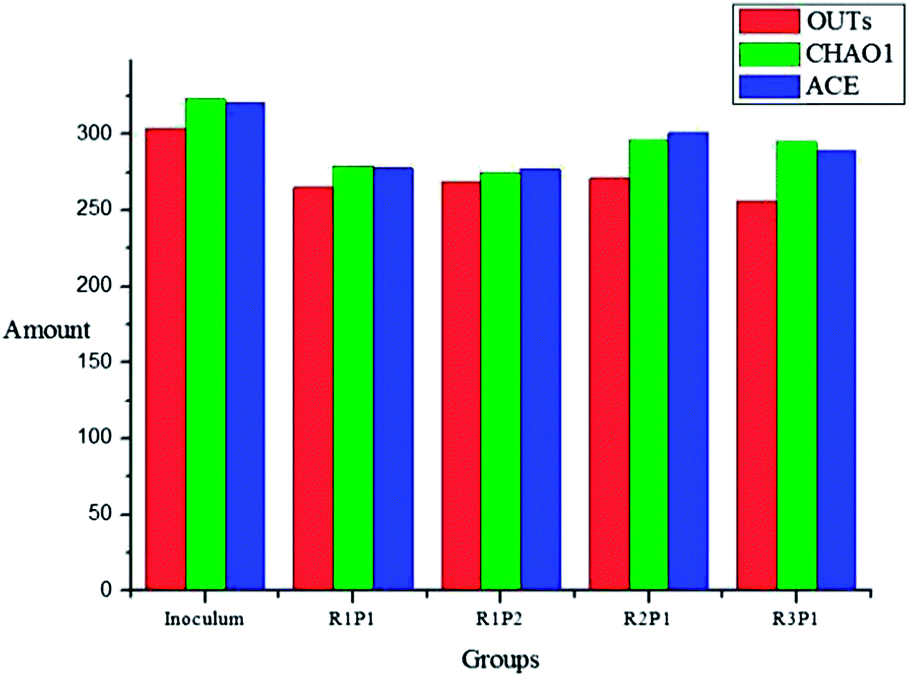 | ||
| Fig. 5 Comparison of the richness and diversity of the 16S RNA gene libraries based on the 0.03 distance. | ||
At the phyla level, Euryarchaeota (>97%) was dominant in all these samples. The genus level identification of the archaea communities is illustrated in Fig. 6. Methanobacterium dominated in all samples. The amounts of other archaea communities are different in 5 groups; this is in accordance with the report of Luo and Angelidaki.21 Furthermore, we assigned the sequences to species level by choosing representative sequences from each dominant OTU. Results indicated that Methanobacterium formicicum was the dominant species in all reactors; this indicated that CH4 was generated by an indirect way. Methanosarcina can mediate both hydrogenotrophic and acetoclastic methanogenesis.14 Therefore, it was also possible that Methanosarcina could utilize H2 directly in R1. For reactor R3, the hydrogenotrophic genus Methanoculleus showed a higher relative abundance, which could be related with the utilization of H2.28 Based on the abovementioned finding, CO was converted to methane mainly by indirect pathway, and H2 was converted to methane mainly by direct pathway.
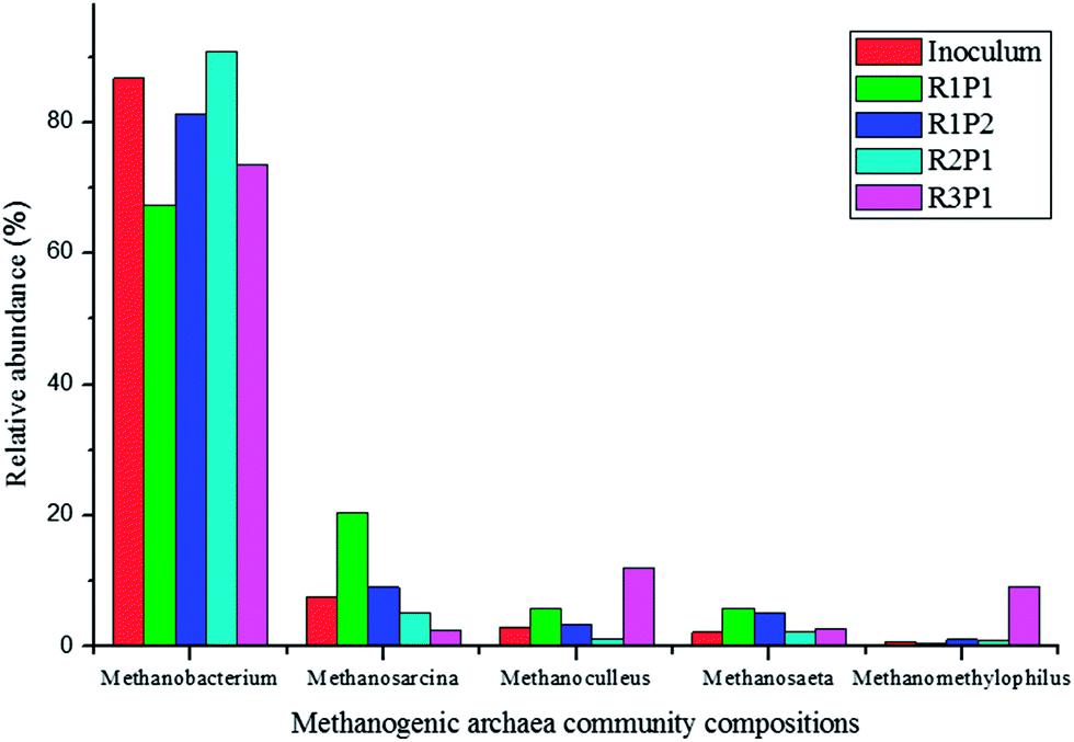 | ||
| Fig. 6 Methanogenic archaea community compositions. | ||
4. Conclusions
Simulated pyrolysis gas (SPG) can be used as a carbon source for biogas production in long-term anaerobic digestion tests. Gas–liquid mass transfer is the limitation for biomethanation of SPG. Gas–liquid mass transfer can be improved by mixing. The addition of H2 to anaerobic reactor could bioupgrade SPG to high quality biogas (91.1% CH4). Pyrolysis combined with anaerobic digestion is an attractive way to utilize biomass and produce higher quality biogas (mainly CH4). Further research on the operation optimization to increase the efficiency of pyrolysis gas biomethanation should be performed. In addition, the effect of impurities on the bioupgradation conversion process should be concerned.Conflicts of interest
There are no conflicts to declare.Acknowledgements
This work was supported by the National Natural Science Foundation of China (No. 51508572), Beijing Municipal Science and Technology Project (No. Z161100001316010), Beijing Nova Program (No. Z171100001117058), and Science Foundation of China University of Petroleum, Beijing (No. 2462014YJRC034 and C201604). Authors also acknowledge the assistance provided by Sheng Deng, Yafei Wang, China University of Petroleum Beijing (CUPB), Beijing, P. R. China, 102249.Notes and references
- S. Ferreira, E. Monteiro, P. Brito and C. Vilarinho, Renewable Sustainable Energy Rev., 2017, 78, 1221–1235 CrossRef.
- J. Liu, L. Yu, Z. Zhao, Y. Chen, P. Zhu, C. Wang, Y. Luo, C. Xu, A. Duan and G. Jiang, J. Catal., 2012, 285, 134–144 CrossRef CAS.
- Y. Luo, V. K. Guda, P. H. Steele and H. Wan, BioResources, 2016, 11, 4415–4431 CAS.
- Y. Luo, V. K. Guda, P. H. Steele, B. Mitchell and F. Yu, Energy Convers. Manage., 2016, 112, 319–327 CrossRef CAS.
- B. Steubing, R. Zah, P. Waeger and C. Ludwig, Renewable Sustainable Energy Rev., 2010, 14, 2256–2265 CrossRef.
- S. Cheng, L. Wei, J. Julson, K. Muthukumarappan, P. R. Kharel and E. Boakye, Fuel Process. Technol., 2017, 162, 78–86 CrossRef CAS.
- Y. Luo, E. B. Hassan, P. Miao, Q. Xu and P. H. Steele, Fuel, 2017, 209, 634–642 CrossRef CAS.
- Y. Li, R. Zhang, Y. He, C. Zhang, X. Liu, C. Chen and G. Liu, Bioresour. Technol., 2014, 156, 342–347 CrossRef CAS PubMed.
- Y. Luo, V. Guda, R. Wijayapala and P. H. Steele, Energy Convers. Manage., 2016, 115, 159–166 CrossRef CAS.
- F. Monlau, C. Sambusiti, N. Antoniou, A. Barakat and A. Zabaniotou, Bioresour. Technol., 2015, 148, 32–38 Search PubMed.
- Y. Li, R. Zhang, Y. He, X. Liu, C. Chen and G. Liu, Energy Fuels, 2014, 28, 3759–3765 CrossRef CAS.
- G. Luo, W. Wang and I. Angelidaki, Environ. Sci. Technol., 2013, 47, 10685–10693 CAS.
- S. R. Guiot, R. Cimpoia and G. Carayon, Environ. Sci. Technol., 2011, 45, 2006–2012 CrossRef CAS PubMed.
- W. Wang, L. Xie, G. Luo, Q. Zhou and I. Angelidaki, Bioresour. Technol., 2013, 146, 234–239 CrossRef CAS PubMed.
- S. Youngsukkasem, K. Chandolias and M. J. Taherzadeh, Bioresour. Technol., 2015, 178, 334–340 CrossRef CAS PubMed.
- E. Oelgeschläger and M. Rother, Arch. Microbiol., 2008, 190, 257–269 CrossRef PubMed.
- X. Liu, Y. Wu, R. Shmulsky, Y. Luo, X. A. Wang, I. W. Chu and H. Wan, BioResources, 2016, 11, 5299–5311 CAS.
- K. Alaimo, R. R. Briefel, E. A. Frongillo Jr and C. M. Olson, Am. J. Public Health, 1998, 88, 419–426 CrossRef CAS PubMed.
- Y. Li, R. Zhang, C. Chen, G. Liu, Y. He and X. Liu, Bioresour. Technol., 2013, 149, 406–412 CrossRef CAS PubMed.
- H. Nie, H. F. Jacobi, K. Strach, C. Xu, H. Zhou and J. Liebetrau, Bioresour. Technol., 2015, 178, 238–246 CrossRef CAS PubMed.
- G. Luo and I. Angelidaki, Appl. Microbiol. Biotechnol., 2013, 97, 3739–3744 CrossRef CAS PubMed.
- G. Luo and I. Angelidaki, Appl. Microbiol. Biotechnol., 2013, 97, 1373–1381 CrossRef CAS PubMed.
- S. K. Khanal, Anaerobic biotechnology for bioenergy production: principles and applications, John Wiley & Sons, 2011 Search PubMed.
- M. Rother and W. W. Metcalf, Proc. Natl. Acad. Sci. U. S. A., 2004, 101, 16929–16934 CrossRef CAS PubMed.
- A. M. Henstra, J. Sipma, A. Rinzema and A. J. Stams, Curr. Opin. Biotechnol., 2007, 18, 200–206 CrossRef CAS PubMed.
- Y. Luo, J. Street, P. Steele, E. Entsminger and V. Guda, BioResources, 2016, 11, 10433–10447 CAS.
- G. Luo, D. Karakashev, L. Xie, Q. Zhou and I. Angelidaki, Biotechnol. Bioeng., 2011, 108, 1816–1827 CrossRef CAS PubMed.
- D. Z. Sousa, M. A. Pereira, A. J. Stams, M. M. Alves and H. Smidt, Appl. Environ. Microbiol., 2007, 73, 1054–1064 CrossRef CAS PubMed.
| This journal is © The Royal Society of Chemistry 2017 |