 Open Access Article
Creative Commons Attribution 3.0 Unported Licence
Solid polymer electrolyte based on ionic bond or covalent bond functionalized silica nanoparticles†
Ji Huab,
Wanhui Wangc,
Ronghua Yua,
Mengke Guoa,
Chengen Hea,
Xiaolin Xie *a,
Haiyan Penga and
Zhigang Xue
 *a
*a
aKey Laboratory for Material Chemistry of Energy Conversion and Storage, Ministry of Education, School of Chemistry and Chemical Engineering, Huazhong University of Science and Technology, Wuhan 430074, China. E-mail: zgxue@mail.hust.edu.cn; xlxie@mail.hust.edu.cn; Fax: +86 27 87543632; Tel: +86 27 87793241
bSchool of Materials Science and Engineering, Luoyang Institute of Science and Technology, Luoyang 471023, China
cSchool of Environmental Engineering and Chemistry, Luoyang Institute of Science and Technology, Luoyang 471023, China
First published on 4th December 2017
Abstract
Although various types of nanoparticle have been ubiquitously employed as additives to promote the practical performances of composite polymer electrolytes (CPEs) in lithium-ion batteries, the influence of the type of chemical bond between the core and canopy of the modified nanoparticle on the properties of CPEs has rarely been investigated. Herein, two types of nanoparticle additive, namely, ionic bond modified nanoparticles (IBNs) and covalent bond modified nanoparticles (CBNs), were prepared conveniently based on nanosilica with different particle sizes in order to optimize the overall performance of the electrolyte. Furthermore, the CPEs were fabricated by doping IBNs or CBNs as well as lithium salts within a poly(ethylene oxide) matrix and their electrochemical properties were investigated. The dramatic enhancement of the ionic conductivity of the CPEs resulted from the addition of fillers into the system, and the improvement became more significant when the fillers were IBNs that used the smaller silica nanoparticle as the core segment, due to the increased chain mobility, as estimated by the smaller Tg value. Moreover, a broad electrochemical stability window was obtained in the presence of IBNs, and the lithium-ion transference number of the system containing lithium bis(trifluoromethanesulfonimide), which has large anions in the structure, was almost two times higher than the CPEs using lithium perchlorate as the lithium source. Therefore, the synergistic effects of the filler structures and the electrolyte compositions are the key factors to improve the electrochemical performances of CPEs.
Introduction
Lithium-ion batteries (LIBs) are one of the most important electrochemical devices for energy storage and they play a crucial role in the modern world because of their widespread applications in portable telecommunication devices, computers, and hybrid electric vehicles. They have become an indispensable part of our daily life due to their high energy density and stable cycling performance.1–4 However, a series of insecure events originating from the use of combustible organic solvents in the system have aroused concern about the security matters of LIBs. To prevent the risks of leakage and related fire hazards, heavy and peculiar packaging structures have to be applied to meet the stringent requisites, but such heavy protective packaging can lead to a reduction in energy density.5 As an alternative, the use of an all-solid construction has been suggested as a preferred solution to these security problems because it possesses several advantages, such as high safety due to a lack of leakage, good chemical stability, and high flexibility within the cell geometry.As solid-state electrolytes, both ceramic electrolytes and polymer electrolytes have been investigated systematically for decades. From the perspective of materials, ceramic electrolytes possess the characteristic of a wide electrochemical stability window. However, the hard and brittle mechanical properties of ceramic electrolytes could result in enhanced interfacial resistance and weak interfacial contact with the electrodes in the cell.6,7 Compared to ceramic electrolytes, solid polymer electrolytes (SPEs) offer advantages, including good processability and flexibility, and they even improve the stability of the cycling performance under high voltage.8–11 Unfortunately, the original SPEs still suffer from relatively poor ionic conduction, which is less than 10−5 S cm−1 at ambient temperature.12 It is generally known that ionic transport takes place in the amorphous electrolyte phase, in which conductivity is two or three orders of magnitude higher than that in the crystalline regions.13
To reduce the crystallizing ability of the polymer electrolytes and further improve the ionic conductivity, composite polymer electrolytes (CPEs) with inorganic fillers incorporated into the polymer skeleton have drawn significant attention from researchers for developing state-of-the-art electrolytes to satisfy the practical application of LIBs.14–19 In CPEs, both the inorganic fillers and polymer matrix retain their own characteristics, and the performances of the composites hinge on the nature of each segment, and also relate to the interactions between the filler and matrix. It is well known that the blending of a filler into a polymer matrix can elevate the ionic conductivity due to the destruction of the crystal of the polymer and further increase the amorphous phase. Moreover, the electrolyte/electrode interfacial properties are improved simultaneously because of the addition of additives.
Undecorated inert fillers, such as α-alumina,20 fumed silica,21 titanium dioxide,22 magnesium oxide23 and other metal oxides have been used to blend with a polymer matrix to fabricate CPEs. Furthermore, the electrolytes on which these composite systems are based consist of varying types of functionalized nanoparticle, and the evolution of electrolyte technology has subsequently been fuelled by these backbone materials. The inorganic fillers can indemnify the declension of the mechanical properties resulting from low crystallinity. Most importantly, the ionic pathway formed in the interphase between the fillers and polymer because of the embedding of these inorganic particles can promote ionic conduction. Besides the pristine state additives, functionalized particles have also been used as fillers to fabricate CPEs. Archer and co-workers developed a novel family of ionically modified nanoparticles that exhibit liquid-like behavior in the absence of solvents.24–27 The core nanostructure was commonly functionalized with a soft organic shell through ion-exchange grafting, and the mobility of these nanoparticles in the polymer was promoted.28 Thereafter, CPEs were further fabricated by utilizing ionic liquid29–31 or sulfonate32 ionically tethered inorganic nanoparticles, which exhibited gratifying mechanical and electrochemical performances. On the other hand, covalently functional nanoparticles have also been justified as effective additives to elevate the properties of solid-state electrolytes.33 In addition, the size and specific surface area of additives also play crucial roles in enhancing the ionic conductivity of CPEs. Smart and Greenbaum investigated the effect of the filler size on the electrochemical properties of CPEs, which indicated that smaller particles, such as those on the nanoscale grade, could improve the physico-chemical performances and make them more pronounced.34 However, the researchers did not carry out a detailed investigation to demonstrate the influence of the functionalized fillers modified by the same component, but with the connections between the core and canopy structure differing as either an ionic bond or a covalent bond, on the practical properties of CPEs.
In this study, two types of inorganic filler were fabricated based on silica nanoparticles with different particle sizes anchored on the same polyether composition; however, the connection between the core segment and the canopy structure was different. Specifically, on the one hand, silica was linked with polyether by sulfo-amino ionic connection to fabricate ionic bond modified nanoparticles (IBNs); on the other hand, silica was coupled with polyether through epoxy-amino association to fabricate covalent bond modified nanoparticles (CBNs). Furthermore, two types of CPE were fabricated with poly(ethylene oxide) as the polymer matrix blended with lithium perchlorates or lithium bis(trifluoromethanesulfonimide) and a certain amount of IBN or CBN. The effect of the filler composition was investigated to provide solid electrolytes with high ionic conductivity and good mechanical stability, and the enhancement became more significant when the fillers were IBNs that consisted of smaller nanosilica, the lithium-ion transference number became higher when lithium bis(trifluoromethanesulfonimide) was used as the lithium source in the system. The nanoparticles modified by an ionic bond were successfully employed as effective fillers to fabricate ideal CPEs, thus the CPEs composed of IBNs acted as potential candidates for application in LIBs.
Experimental
Materials
Poly(ethylene oxide) (PEO, Mw = 6 × 10⁵ g mol−1, Acros), LUDOX® SM colloidal silica (30 wt% suspension in H2O, Sigma-Aldrich), 3-mercaptopropyltrimethoxysilane (MPTMS, 95 wt%, Sigma-Aldrich) and 3-glycidoxypropyltrimethoxysilane (GPTMS, 98 wt%, Sigma-Aldrich) were used as received. Lithium perchlorate (LiClO4, Aladdin) and lithium bis(trifluoromethanesulfonimide) (LiTFSI, Macklin) were dried at 150 °C in a vacuum oven for 24 h and stored in a glove box before use. The monoamine-terminated PEO derivative, JEFFAMINE® M2070, was gained form Huntsman Co., Ltd. Other chemicals, including alcohol, tetraethyl orthosilicate (TEOS), ammonia, hydrogen peroxide, acetonitrile, lithium iron phosphate (LFP), acetylene black (AB), polyvinylidene fluoride (PVDF), and N-methyl-2-pyrrolidone (NMP) were purchased locally. De-ionized (DI) water was used in all the experiments.Preparation of nanosilica
According to the Stöber method,35 330 mL of ethanol, 11 mL of ammonia, and 110 mL of DI water in a 3-necked flask were vigorously stirred at ambient temperature for 0.5 h. Then 20 mL of TEOS was added quickly to the flask, and the reaction continued with vigorous stirring for 24 h. After being washed three times with ethanol, the silica nanoparticles were dried under vacuum at 50 °C for 24 h.Preparation of functionalized silica nanoparticles
The fabrication of the IBNs was inspired by the method proposed in the literature.36 MPTMS (10 mL) was dissolved in ethanol (40 mL) to form a transparent solution. Then the solution was dripped into nanosilica prepared previously (6 g) and combined with DI water (180 mL) by intense mechanical stirring (700 rpm). The reaction was carried out under reflux at 70 °C for 24 h. After being separated by centrifugation and washing three times with ethanol to remove unreacted MPTMS, the thiol coated silica nanoparticles, SiO2–SH, were obtained by drying at 60 °C under vacuum for 24 h. The sulfonation of the silica nanoparticles (hereafter SiO2–SO3H) was further performed by oxidizing the surface thiol groups of the silica into sulfonic acid groups with 30 wt% H2O2 solution at 25 °C for 24 h. Then, the IBNs were prepared by acid–base neutralization between the sulfonic acid groups of the SiO2–SO3H and the amino groups terminating on JEFFAMINE® M2070.37 Briefly, SiO2–SO3H (10 g) was added to DI water, and the mixture was ultrasonicated for 30 min to promote the dispersion of SiO2–SO3H in the solution. JEFFAMINE® M2070 (10 g) was also dissolved in DI water (50 mL) separately, and SiO2–SO3H solution was added with continuous stirring. The linking reaction was allowed to proceed to completion over several days, and the termination of the reaction was evaluated by the changes in the pH value. The product was put into dialysis tubing and dialyzed for several days in DI water to remove any remaining free JEFFAMINE® M2070. The water was evaporated in a convection oven and the product was dried extensively under vacuum and stored in its dried form at room temperature. The variation in the proportion of SiO2–SO3H to JEFFAMINE® M2070 caused the difference in the grafting density of the ionic segment modified on silica. In order to gain IBNs with various particle sizes, LUDOX® SM colloidal silica was used as the core component to fabricate the functionalized nanosilica via the same formerly mentioned method.CBNs were prepared by the following two steps: first, silica nanoparticles (LUDOX® SM colloidal silica) were decorated with GPTMS, and the reaction route was analogous to the method for fabricating SiO2–SH. The purpose of this step was to produce epoxide group modified silica, designated as SiO2–EP. Second, following the similar procedure for preparing IBNs, CBNs were synthesized facilely due to the covalent connection between the epoxide group terminated on SiO2–EP and the amino group of JEFFAMINE® M2070.38 The purification of CBNs was also carried out according to the post-treatment approach of IBNs.
Electrolyte preparation
The CPEs containing IBNs as fillers were prepared via solution casting procedure.39,40 Appropriate amounts of IBNs, PEO, and lithium salts (LiClO4 or LiTFSI, EO/Li+ = 16) were dispersed in acetonitrile and stirred for 16 h at room temperature, and the IBN content of the system was fixed at 30 wt%. After PEO was dissolved in acetonitrile, the mixture was a homogeneous composition, and this was then poured into a PTFE dish. The solvent was slowly evaporated and further dried in a vacuum drying oven for 48 h to eliminate the trace content of acetonitrile, and a solid-state flexible membrane was thus obtained. The thickness of the film was kept at about 100 μm. This kind of CPE consisted of different lithium salts, which were denoted as CPE-IBN-LiClO4 and CPE-IBN-LiTFSI. Moreover, the CPEs composed of CBNs that used LiClO4 as a lithium source (CPE-CBN-LiClO4) were prepared following a similar procedure.Physico-chemical characterization
The structure of the raw material, such as pristine SiO2, as well as products including SiO2–SH, SiO2–SO3H, IBNs, SiO2–EP, and CBNs were characterized via Fourier transformation infrared absorption (FT-IR) spectroscopy using an FT interferometer (Equinox 55, Bruker, Germany). The grafting densities of the IBNs and CBNs were estimated by an STA449F3 Jupiter thermogravimetric analyzer (Netzsch, Germany) in the temperature range from ambient temperature to 800 °C at a heating rate of 10 °C min−1 under a nitrogen atmosphere. All the samples were dried at 60 °C under vacuum overnight before testing. Scanning electron microscopy (SEM, Nova NanoSEM 450, FEI, Netherlands) and transmission electron microscopy (TEM, Tecnai G2 20, FEI, Netherlands) were used to evaluate the particle morphology. Energy dispersive X-ray (EDX, Nova NanoSEM 450, FEI, Netherlands) mapping was employed to detect the homogeneity of the fillers in the chemical composition. The crystal structure of the CPEs was detected via the X-ray diffraction (XRD, X’Pert PRO, PANalytical B.V., Netherlands) data using Cu Kα radiation (40 mA/40 kV). Differential scanning calorimetry (DSC) was performed on a Q2000 TA Instrument (USA) for a temperature range of −90 to 150 °C under an argon atmosphere at a constant heating rate of 10 °C min−1.Electrochemical characterization
The ionic conductivity, electrochemical stability window, and lithium-ion transference number were carried out on an Autolab PGSTAT302N electrochemical test system (Eco Chemie, Netherlands). The ionic conductivity was determined by the two electrode AC impedance method over a frequency range from 1 MHz to 100 Hz using a sinusoidal amplitude modulation of 10 mV at temperatures ranging from 20 to 60 °C at 10 °C intervals. An ionic conductivity measurement cell containing two stainless steel (SS) electrodes was employed, and the cells were held at each temperature for more than 30 min to equilibrate prior to testing. The ionic conductivity was calculated by utilizing the equation σ = L/(SR), where L is the thickness of the electrolyte film, S is the contact area between the electrolyte and electrode, and R is the bulk resistance of the electrolyte. The electrochemical stability window of the CPEs was obtained by linear sweep voltammetry (LSV) at a sweep rate of 10 mV s−1. The samples were sandwiched between lithium foil and an SS electrode in a coin cell CR2032 assembled in an argon-filled glove box. The lithium-ion transference number (tLi+) of the polymer electrolyte was determined at 50 °C based on the method described elsewhere.41,42 The impedance of the symmetrical cell (Li|electrolyte|Li) was tested before and after polarization with a fixed DC voltage pulse, ΔV = 20 mV. The initial current is I0, and the current after decaying to a steady state is denoted as Iss. The equation tLi+ = Iss(ΔV − I0R0)/I0(ΔV − IssRss) was used to calculate tLi+, where R0 and Rss are the interfacial resistances before and after polarization.Results and discussion
Fabrication of the inorganic fillers and electrolyte membranes
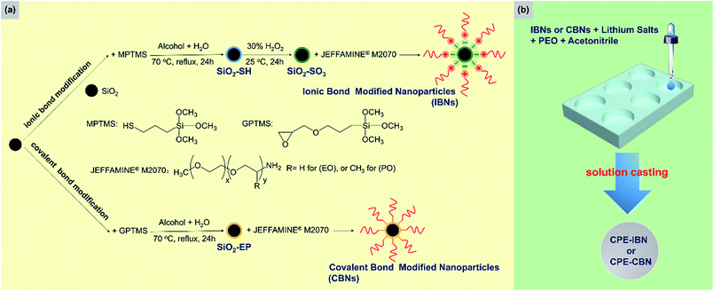
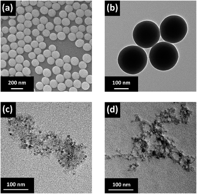
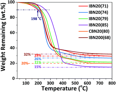
Two types of inorganic fillers were utilized in this study, including IBNs and CBNs, which were prepared through a simple and scalable method based on silica nanoparticles. A schematic illustration of the fabrication routes of the fillers and electrolyte membranes is shown in Fig. 1. The SEM micrograph for nanosilica prepared via Stöber method confirmed its nano-particulate nature and Fig. 2a clearly showed that the nanosilica grain size was estimated to be approximately 130 nm, after grafting JEFFAMINE® M2070 through the ionic bond, and the size of this kind of IBN was about 200 nm (Fig. 2b). However, the size of the IBNs or CBNs fabricated based on LUDOX® SM colloidal silica was about 20 nm (Fig. 2c and d). In this study, only the type of filler was varied, the content of the fillers remained constant for all CPEs (30 wt%), which was basically targeted to understand the influence on the physical and electrochemical properties induced by the additive structure. To begin with, the electrolyte membranes consisting of only PEO mixture were nearly translucent films; however, CPEs with incorporated IBNs or CBNs resulted in opaque but white membranes (Fig. S1a, ESI†). All the CPEs were flexible, indicating that the mechanical property was improved because of the addition of the fillers (Fig. S1b, ESI†).By altering the grafting density, the compositions of the IBNs were varied, which were denoted as IBNx(y), where x is the size of the functionalized nanoparticles in nm and y is the weight percentage of the component anchored on silica nanoparticles, as obtained from the TGA results shown in Fig. 3. Like the IBNs, the CBNs were denoted as CBN20(80). For the CPEs composed of IBNs, two types of lithium salt, such as LiClO4 or LiTFSI, were used as the lithium source in the system, which were abbreviated to CPE-IBNx(y)-LiClO4 or CPE-IBNx(y)-LiTFSI, respectively. In contrast, the CPEs with embedded CBNs and LiClO4 were represented as CPE-CBN20(80)-LiClO4. The TGA diagrams demonstrate significant weight loss, which originated from the organic composition of the IBNs or CBNs. Otherwise, before thermal decomposition, a slight weight loss of around 2% was observed for some samples, and this was probably due to the evaporation of the physically absorbed moisture.43 The functionalized nanoparticles clearly exhibited the following two types of distinct weight loss events: continuous rapid decomposition at approximately 200 °C due to the degradation of the anchored segment and the relatively slow weight loss region at around 400–700 °C due to the intermolecular condensation of the silica nanoparticles. The high decomposition temperature of the IBNs or CBNs (approximately 200 °C) indicated their outstanding thermal stabilities.
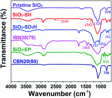
The IBNs were prepared via the sulfonation of silica nanoparticles, and subsequently the neutralization reaction between SiO2–SO3H and JEFFAMINE® M2070 was promoted. Moreover, CBNs were prepared by a covalently linked reaction between the epoxide group decorated silica nanoparticle (SiO2–EP) and JEFFAMINE® M2070 (Fig. 1). The FT-IR spectra of the pristine silica, SiO2–SH, SiO2–SO3H, IBN20(79), SiO2–EP, and CBN20(80) are shown in Fig. 4. For bare silica, the characteristic absorption peak of the tetrahedral silica structures at 1105 cm−1 (Si–O stretching), as well as the Si–O–Si bending peak at 808 cm−1 are both observed. In the spectrum of SiO2–SH, there is a small peak at 2556 cm−1 (S–H stretching), indicating the existence of a thiol group. Moreover, the peak at 1342 cm−1 corresponding to the C–H bending vibration can also be observed. In the spectrum of SiO2–SO3, the S–H stretching vibration peak disappears; however, three characterization peaks at 1192 cm−1 (S![[double bond, length as m-dash]](https://www.rsc.org/images/entities/char_e001.gif) O stretching), 1053 cm−1 (S
O stretching), 1053 cm−1 (S![[double bond, length as m-dash]](https://www.rsc.org/images/entities/char_e001.gif) O stretching), and 741 cm−1 (S–O stretching) emerge, indicating the oxidation of the thiol group into a sulfonic acid group. Compared to SiO2–SO3, a peak at 1468 cm−1 attributed to the NH3+ deformation vibration is observed for IBN20(79), demonstrating the ionic modification of the silica nanoparticle. As illustrated in the spectrum of SiO2–EP, the peak at 910 cm−1 (epoxy stretching) elucidates the successful grafting of the epoxy group on silica. However, the characteristic epoxy band at 910 cm−1 disappears in the spectra of CBN20(80), indicating the complete reaction of most of the epoxy groups with the amino groups. Furthermore, the peak at 798 cm−1, which originates from the tertiary amine deformation vibration, also proves that JEFFAMINE® M2070 has been coated on the surface of the silica by covalent connection via the epoxy-amino reaction.
O stretching), and 741 cm−1 (S–O stretching) emerge, indicating the oxidation of the thiol group into a sulfonic acid group. Compared to SiO2–SO3, a peak at 1468 cm−1 attributed to the NH3+ deformation vibration is observed for IBN20(79), demonstrating the ionic modification of the silica nanoparticle. As illustrated in the spectrum of SiO2–EP, the peak at 910 cm−1 (epoxy stretching) elucidates the successful grafting of the epoxy group on silica. However, the characteristic epoxy band at 910 cm−1 disappears in the spectra of CBN20(80), indicating the complete reaction of most of the epoxy groups with the amino groups. Furthermore, the peak at 798 cm−1, which originates from the tertiary amine deformation vibration, also proves that JEFFAMINE® M2070 has been coated on the surface of the silica by covalent connection via the epoxy-amino reaction.
The physical properties of the electrolyte membrane
To confirm the influence of the added IBN or CBN inorganic fillers on the CPEs and the changes in the crystalline structure of the as-fabricated electrolyte, XRD measurements were carried out at room temperature (Fig. 5), and the FWHM value for the diffraction peak of each sample could be concluded from Fig. S2 (ESI†). Compared to the XRD pattern of the solid polymer electrolyte composed of only PEO and LiClO4 (EO/Li+ = 16) without any blended additive (hereafter abbreviated as SPE-PEO-LiClO4), the characteristic diffraction peaks of the crystalline PEO between 2θ = 17° and 25° became weaker and broader when IBNs or CBNs were introduced to the electrolyte system, thus indicating that the coordination interactions between the fillers and the polymer matrix could decrease the crystallinity of PEO.44,45 The phenomenon became more obvious when the fillers were IBNs. In addition, the diffraction peaks of CPE-IBN20(79)-LiClO4, CPE-CBN20(80)-LiClO4, and CPE-IBN200(68)-LiClO4 were all slightly smaller than those of the sample consisting of PEO doping with LiClO4 (EO/Li+ = 16) and the silica nanoparticles fabricated via the Stöber method mentioned above at 30 wt% (hereafter abbreviated as CPE-SiO2130-LiClO4, where 130 was the particle size estimated by SEM, Fig. 2). Because the grain size of the additive and the type of lithium salt were also similar in CPE-IBN200(68)-LiClO4 and CPE-SiO2130-LiClO4, the smaller diffraction peak in the XRD pattern of CPE-IBN200(68)-LiClO4 arose from the shell segment grafted on the surface of the silica nanoparticles, which increased the amorphous domain of the PEO matrix in the system. Unfortunately, obvious aggregation of the pristine SiO2 emerged in CPE-SiO2130-LiClO4, illustrated in the EDX micrograph, and in contrast to this result, CPE-IBN200(68)-LiClO4 was comprised of well-dispersed spherical nanoparticles (IBN200(68)) due to the balanced charge caused by sulfo-amino neutralization between the core and shell structures (Fig. S3, ESI†).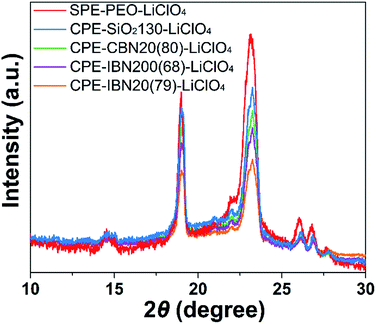 | ||
| Fig. 5 The XRD patterns of CPE-CBN20(80)-LiClO4, SPE-PEO-LiClO4 and the CPEs containing IBNs with various grafting densities. The weight ratio of the fillers in the CPEs was fixed at 30 wt%. | ||
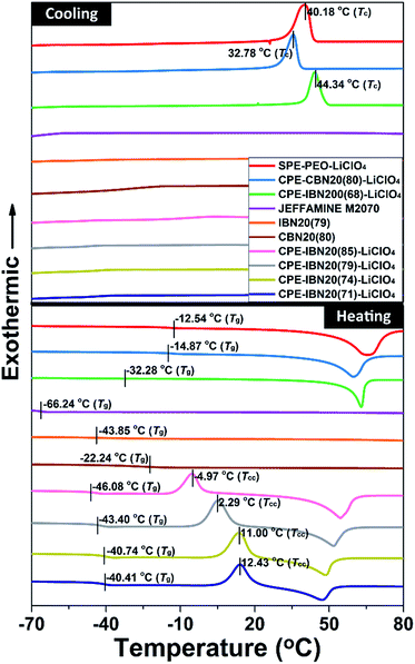
The thermal behaviors of the CPE samples, evaluated by DSC, together with those of JEFFAMINE® M2070, IBN20(79), CBN20(80) and the SPE-PEO-LiClO4, are shown in Fig. 6. The glass transition temperature (Tg) is known to be a crucial factor that influences the ionic conductivity of the polymer electrolytes, as ionic transference occurs only in the amorphous region (above Tg) of the polymer matrix. Thus, the composite material with low value of Tg is more advantageous to ionic conduction.43 As illustrated in both the DSC curves and Table 1, the Tg of JEFFAMINE® M2070 is −66.24 °C, which is a relatively low value because JEFFAMINE® M2070 is a viscous liquid due to the smaller molecular weight of around 2000 g mol−1. However, the Tg of IBN20(79) is enhanced to −43.85 °C, and the Tg of CBN20(80) is further increased to −22.24 °C. The obvious enhancements of Tg indicate that the segment mobility of JEFFAMINE® M2070 is suppressed when the silica nanoparticles are anchored to JEFFAMINE® M2070 through chemical connection, and the trend become more distinct owing to the covalent linkage between the inorganic core and organic shell. The CPE-IBN series have much lower Tg values than those of SPE-PEO-LiClO4 as well as CPE-CBN-LiClO4, indicating the generation of a weak ion–dipole interaction in the system because of the introduction of IBNs. It is noteworthy that, compared with the higher Tg of SPE-PEO-LiClO4, the Tg values of the IBN20(79) and CPE-IBN20 samples are all approximately −40 °C, suggesting that the improved mobility of the polymer chains in CPEs mainly originates from the activity of the tethered polyether grafted on the surface of IBNs. In addition, the same phenomenon can be found in the CPE-CBN series because the Tg values of CBN20(80) and CPE-CBN20(80)-LiClO4 are almost the same and −20 °C, demonstrating that the organic segment functionalized on the silica nanoparticles dominates the polymer chain mobility of the CPEs. IBNs and CBNs possess the same shell structure (JEFFAMINE® M2070), and the significant distinction in the thermal features of CPE-IBN and CPE-CBN merely results from the type of linkage between the core and shell segments of the two types of nanoscale filler. Moreover, the Tg of CPE-IBN200(68)-LiClO4 is −32.28 °C, which is around 10 °C higher than the values of the CPEs embedding IBNs with a grain size of 20 nm. Clearly, the small particle sizes lead to an increase in the specific surface area, and the dispersed low-particle-size fillers influence the recrystallization kinetics of the PEO matrix, thus ultimately improving the localized amorphous regions.46,47 On the other hand, the obvious exothermic peaks can be observed in the DSC curves of CPE-IBN200(68)-LiClO4, CPE-CBN20(80)-LiClO4, and SPE-PEO-LiClO4 during the cooling process, which are attributed to the crystalline transition of the materials. The peak temperature of crystallization (Tc) for the three entries is 44.34, 32.78 and 40.18 °C, respectively. Very interestingly, no exothermic peak appears in the cooling procedure for the CPE-IBN20 series, indicating that crystals cannot be formed during cooling. However, the clear existence of the exothermic peaks in the heating DSC curves of the CPE-IBN20 series due to cold crystallization indicated the formation of crystals. Furthermore, the cold crystallization temperature (Tcc) gradually shifts to the lower temperature region with increasing grafting density of the IBNs. Obviously, the shift of Tcc to a lower temperature is related to the nucleation effect of the pre-existing PEO crystallites, which promotes the occurrence of cold crystallization at a relatively low temperature.48 The other possibility is related to the enhanced mobility of the molecular chains, which is induced by the increase in the free polymer chains on the shell structure of the IBNs due to weaker ionic connection. The test conditions, viz. the cooling/heating rate, remained unchanged for all the DSC measurements, therefore, the differences in the crystallization behavior were mainly caused by the composite structure. The above mentioned results indicate that CPE-IBN tends to form an amorphous phase more obviously when the grain sizes of the fillers are smaller, and the mobility of the molecular chains is improved. Therefore, we suggest that the IBNs play a dual role in the composite electrolyte: the core structure depresses crystallinity similar to the performance in other organic–inorganic hybrid electrolytes, and the shell segment acts as an extra plasticizer to retard crystallization because of the free state induced by ionic linkage.
| Entrya | Tg/°C | Tc/°C | Tcc/°C |
|---|---|---|---|
| a LiClO4 is used for all the entries (EO/Li+ = 16), and the weight ratio of the fillers is fixed at 30 wt% in all the CPE entries.b No signal observed in the DSC curves. | |||
| JEFFAMINE® M2070 | −66.24 | —b | —b |
| IBN20(79) | −43.85 | —b | —b |
| CBN20(80) | −22.24 | —b | —b |
| CPE-IBN20(71)-LiClO4 | −40.41 | —b | 12.43 |
| CPE-IBN20(74)-LiClO4 | −40.74 | —b | 11.00 |
| CPE-IBN20(79)-LiClO4 | −43.40 | —b | 2.29 |
| CPE-IBN20(85)-LiClO4 | −46.08 | —b | −4.97 |
| CPE-IBN200(68)-LiClO | −32.28 | 44.34 | —b |
| CPE-CBN20(80)-LiClO4 | −14.87 | 32.78 | —b |
| SPE-PEO-LiClO4 | −12.54 | 40.18 | —b |
Electrochemical properties of the electrolyte membrane
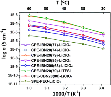
The ionic conductivity is a crucial property for the application of solid-state electrolytes in energy storage devices.49 Fig. 7 exhibits the temperature dependence of the ionic conductivities for CPE-CBN20(80)-LiClO4, SPE-PEO-LiClO4, and CPE-IBNs consisting of various fillers sizes and lithium salts. As expected, the ionic conductivity increases with increasing temperature for all the samples owing to the faster movement of the ions and improved flexibility of the polymer chains. The ionic conductivities of the CPEs are higher than those of SPE-PEO-LiClO4 at all temperature ranges investigated, indicating that the addition of IBNs or CBNs enhances the ionic conductivity of the composite solid electrolyte. Furthermore, most CPEs containing IBN20 and LiClO4 exhibit higher ionic conductivity than CPE-CBN20(80)-LiClO4, and CPE-IBN20(79)-LiClO4 owns the highest ionic conductivity of 3.74 × 10⁻⁵ S cm−1 at ambient temperature, which is attributed to the lower Tg of the material and which promotes polymer chain relaxation.50 In other words, the enhanced ionic conductivity of CPE-IBN20 can be attributed to the incorporation of the ionic bond coated nanoscale fillers. The increase in the ionic conductivities of the CPEs compared to that of SPE-PEO-LiClO4 also arises from the reduction in the crystallinity of the PEO phase by adding ceramic fillers (IBNs or CBNs), as explained in Fig. 5. But, undeniable as it is, the ionic conductivity of CPE-IBN20(85)-LiClO4, which is composed of fillers with more ionic content, is a little lower than that of CPE-IBN20(79)-LiClO4. This result indicates that ionic conductivity is not only caused by the relaxation of the polymer chains, but also the lithium ion mobility. A higher grafting density is associated with high melt viscosity,51 which hampers the lithium ion conduction. In addition, when IBNs with relatively large grain sizes (≈200 nm) are used as fillers in the CPEs, the ionic conductivity is obviously lower than CPE-CBN20(80)-LiClO4 in contrast. As is known, the cation–anion coupling can be reduced because of the interaction between the anions and the surfaces of the nanoparticles, the nanoparticle surface–polymer interface can form a new ionic pathway for promoting ionic conduction,34 and the improvement will be more prominent as the filler sizes trend to smaller. Clearly, the differences between the ionic conductivities of CPE-IBN20(79)-LiClO4 and CPE-IBN20(79)-LiTFSI are subtle, indicating that the ionic conductivities obtained in this study yield no definitive trends regarding the type of lithium salt. Consequently, the conductivity performance of the CPEs is determined by the synergistic effect between the type of the chemical bond of the modified additives, as well as the grafting densities and grain sizes of the functionalized fillers.The electrochemical stability window of the CPEs was observed by LSV, and the resulting LSV curves are shown in Fig. S4 (ESI†). The anodic current onset in the current–voltage curve is related to the electrochemically oxidized decomposition of the electrolyte. The LSV results of the CPEs show that no decomposition in the electrolyte takes place below 5.0 V vs. Li+/Li, revealing that the CPEs have high anodic stability. Fig. S5 (ESI†) shows the results of DC polarization and the AC impedance measurements for the CPE-IBN20(79)-LiTFSI system. Because the free anions in the composite can be trapped by the functionalized ceramic fillers, which has been proven by our previous studies,52 the obtained tLi+ is 0.44. The other tLi+ values of the CPE-IBN-LiClO4 samples are listed in Table 2. These values are almost the same as those for PEO-based electrolytes, which exhibited tLi+ below 0.4.53,54
| Entrya | σb/S cm−1 | tLi+ |
|---|---|---|
| a The weight ratio of the fillers is fixed at 30 wt% in all the CPE entries.b The data shown here is the ionic conductivity at 30 °C.c Not detected for these samples. | ||
| CPE-IBN20(71)-LiClO4 | 3.04 × 10⁻⁶ | 0.22 |
| CPE-IBN20(74)-LiClO4 | 4.66 × 10⁻⁶ | 0.21 |
| CPE-IBN20(79)-LiClO4 | 3.74 × 10⁻⁵ | 0.22 |
| CPE-IBN20(85)-LiClO4 | 1.52 × 10⁻⁵ | 0.23 |
| CPE-IBN200(68)-LiClO4 | 1.69 × 10⁻⁶ | —c |
| CPE-IBN20(79)-LiTFSI | 3.57 × 10⁻⁵ | 0.44 |
| CPE-CBN20(80)-LiClO4 | 4.69 × 10⁻⁶ | —c |
| SPE-PEO-LiClO4 | 4.61 × 10⁻⁷ | —c |
Conclusions
In this study, ionic or covalent bond modified nanoparticles (IBNs or CBNs) were synthesized successfully. The composite polymer electrolytes composed of PEO-LiClO4/LiTFSI as well as IBNs or CBNs were prepared as thin films by a solution casting process, and their electrochemical properties were investigated. Compared to the bare PEO based electrolyte without blended nanoscale fillers, the CPEs exhibited enhanced ionic conductivities at ambient temperature when a certain content (30 wt%) of additives was added, and the improvement became more exciting when the fillers were IBNs with smaller grain size. The results indicated that the core materials of the IBNs could depress the crystallization of the polymer matrix, the shell segment acted as an extra plasticizer to retard crystallization due to the free state induced by the weak ionic connection, and the improvement became more significant when the filler size was smaller. Furthermore, when LiTFSI was embedded in the system, the lithium-ion transference number was almost two times higher than those of the CPE-IBN-LiClO4 samples because of the large anions in the structure of LiTFSI. In a word, the performances of the CPEs were mainly influenced by the type of chemical bond of the modified additives, together with the grafting densities and particle size of the modified silica nanoparticles. The enhanced ionic conductivity and good electrochemical stability indicate that IBNs are efficient fillers for promoting the performances of solid-state electrolytes, and thus it is expected that CPE-IBN can potentially be applied to solid-state LIBs.Conflicts of interest
There are no conflicts to declare.Acknowledgements
The authors are grateful to the National Natural Science Foundation of China (Grant No. 51473056, 51622303, 51703080, and 51210004) and Fundamental Research Funds for the Central Universities (2016JCTD112) for their support of this work. The authors also gratefully acknowledged the Analytical and Testing Center of HUST for use of their measurement facilities.References
- V. Etacheri, R. Marom, R. Elazari, G. Salitra and D. Aurbach, Energy Environ. Sci., 2011, 4, 3243–3262 CAS.
- B. Dunn, H. Kamath and J.-M. Tarascon, Science, 2011, 334, 928–935 CrossRef CAS PubMed.
- M. Armand and J. M. Tarascon, Nature, 2008, 451, 652–657 CrossRef CAS PubMed.
- M. Winter and R. J. Brodd, Chem. Rev., 2004, 104, 4245–4270 CrossRef CAS PubMed.
- L. Porcarelli, C. Gerbaldi, F. Bella and J. R. Nair, Sci. Rep., 2016, 6, 19892 CrossRef CAS PubMed.
- Y.-C. Jung, M.-S. Park, C.-H. Doh and D.-W. Kim, Electrochim. Acta, 2016, 218, 271–277 CrossRef CAS.
- J. W. Fergus, J. Power Sources, 2010, 195, 4554–4569 CrossRef CAS.
- Y. Kobayashi, K. Shono, T. Kobayashi, Y. Ohno, M. Tabuchi, Y. Oka, T. Nakamura and H. Miyashiro, J. Power Sources, 2017, 341, 257–263 CrossRef CAS.
- E. Quartarone and P. Mustarelli, Chem. Soc. Rev., 2011, 40, 2525–2540 RSC.
- H. Zhang, C. Li, M. Piszcz, E. Coya, T. Rojo, L. M. Rodriguez-Martinez, M. Armand and Z. Zhou, Chem. Soc. Rev., 2017, 46, 797–815 RSC.
- W. H. Meyer, Adv. Mater., 1998, 10, 439–448 CrossRef CAS PubMed.
- L. Z. Long, S. J. Wang, M. Xiao and Y. Z. Meng, J. Mater. Chem. A, 2016, 4, 10038–10069 CAS.
- C. Berthier, W. Gorecki, M. Minier, M. B. Armand, J. M. Chabagno and P. Rigaud, Solid State Ionics, 1983, 11, 91–95 CrossRef CAS.
- S. Gao, J. Zhong, G. Xue and B. Wang, J. Membr. Sci., 2014, 470, 316–322 CrossRef CAS.
- Q. Lu, J. Fang, J. Yang, R. Miao, J. Wang and Y. Nuli, J. Membr. Sci., 2014, 449, 176–183 CrossRef CAS.
- Q. Lu, J. Fang, J. Yang, G. Yan, S. Liu and J. Wang, J. Membr. Sci., 2013, 425–426, 105–112 CrossRef CAS.
- A. Agrawal, S. Choudhury and L. A. Archer, RSC Adv., 2015, 5, 20800–20809 RSC.
- Q. H. Cheng, W. He, X. D. Zhang, M. Li and X. Song, RSC Adv., 2016, 6, 10250–10265 RSC.
- R. Senthil Kumar, M. Raja, M. Anbu Kulandainathan and A. Manuel Stephan, RSC Adv., 2014, 4, 26171–26175 RSC.
- J. E. Weston and B. C. H. Steele, Solid State Ionics, 1982, 7, 75–79 CrossRef CAS.
- S. A. Khan, G. L. Baker and S. Colson, Chem. Mater., 1994, 6, 2359–2363 CrossRef CAS.
- A. S. Best, A. Ferry, D. R. MacFarlane and M. Forsyth, Solid State Ionics, 1999, 126, 269–276 CrossRef CAS.
- B. Kumar, S. J. Rodrigues and L. G. Scanlon, J. Electrochem. Soc., 2001, 148, A1191–A1195 CrossRef CAS.
- A. B. Bourlinos, K. Raman, R. Herrera, Q. Zhang, L. A. Archer and E. P. Giannelis, J. Am. Chem. Soc., 2004, 126, 15358–15359 CrossRef CAS PubMed.
- A. B. Bourlinos, S. R. Chowdhury, D. D. Jiang, Y.-U. An, Q. Zhang, L. A. Archer and E. P. Giannelis, Small, 2005, 1, 80–82 CrossRef CAS PubMed.
- A. B. Bourlinos, R. Herrera, N. Chalkias, D. D. Jiang, Q. Zhang, L. A. Archer and E. P. Giannelis, Adv. Mater., 2005, 17, 234–237 CrossRef CAS.
- A. B. Bourlinos, S. Ray Chowdhury, R. Herrera, D. D. Jiang, Q. Zhang, L. A. Archer and E. P. Giannelis, Adv. Funct. Mater., 2005, 15, 1285–1290 CrossRef CAS.
- D. Shah, P. Maiti, D. D. Jiang, C. A. Batt and E. P. Giannelis, Adv. Mater., 2005, 17, 525–528 CrossRef CAS.
- Y. Lu, S. K. Das, S. S. Moganty and L. A. Archer, Adv. Mater., 2012, 24, 4430–4435 CrossRef CAS PubMed.
- Y. Lu, K. Korf, Y. Kambe, Z. Tu and L. A. Archer, Angew. Chem., Int. Ed. Engl., 2014, 53, 488–492 CrossRef CAS PubMed.
- S. S. Moganty, N. Jayaprakash, J. L. Nugent, J. Shen and L. A. Archer, Angew. Chem., Int. Ed. Engl., 2010, 49, 9158–9161 CrossRef CAS PubMed.
- Y.-S. Lee, J. H. Lee, J.-A. Choi, W. Y. Yoon and D.-W. Kim, Adv. Funct. Mater., 2013, 23, 1019–1027 CrossRef CAS.
- H. Zhang, P. Maitra and S. L. Wunder, Solid State Ionics, 2008, 178, 1975–1983 CrossRef CAS.
- I. W. Cheung, K. B. Chin, E. R. Greene, M. C. Smart, S. Abbrent, S. G. Greenbaum, G. K. S. Prakash and S. Surampudi, Electrochim. Acta, 2003, 48, 2149–2156 CrossRef CAS.
- W. Stöber, A. Fink and E. Bohn, J. Colloid Interface Sci., 1968, 26, 62–69 CrossRef.
- Y. Wang, D. Yang, X. Zheng, Z. Jiang and J. Li, J. Power Sources, 2008, 183, 454–463 CrossRef CAS.
- P. Agarwal, H. Qi and L. A. Archer, Nano Lett., 2010, 10, 111–115 CrossRef CAS PubMed.
- Q. Pan, D. M. Smith, H. Qi, S. Wang and C. Y. Li, Adv. Mater., 2015, 27, 5995–6001 CrossRef CAS PubMed.
- F. L. Deng, X. E. Wang, D. He, J. Hu, C. L. Gong, Y. S. Ye, X. L. Xie and Z. G. Xue, J. Membr. Sci., 2015, 491, 82–89 CrossRef CAS.
- X. E. Wang, C. L. Gong, D. He, Z. G. Xue, C. Chen, Y. G. Liao and X. L. Xie, J. Membr. Sci., 2014, 454, 298–304 CrossRef CAS.
- G. B. Appetecchi, G. Dautzenberg and B. Scrosati, J. Electrochem. Soc., 1996, 143, 6–12 CrossRef CAS.
- P. G. Bruce, J. Evans and C. A. Vincent, Solid State Ionics, 1988, 28, 918–922 CrossRef.
- P. Wang, Y.-N. Zhou, J.-S. Luo and Z.-H. Luo, Polym. Chem., 2014, 5, 882–891 RSC.
- S. Kim and S. J. Park, Electrochim. Acta, 2007, 52, 3477–3484 CrossRef CAS.
- Z. Tang, J. M. Wang, Q. Q. Chen, W. C. He, C. Shen, X. X. Mao and J. Q. Zhang, Electrochim. Acta, 2007, 52, 6638–6643 CrossRef CAS.
- F. Croce, G. B. Appetecchi, L. Persi and B. Scrosati, Nature, 1998, 394, 456–458 CrossRef CAS.
- J. B. Goodenough and K.-S. Park, J. Am. Chem. Soc., 2013, 135, 1167–1176 CrossRef CAS PubMed.
- H. M. Chen, X. C. Du, A. S. Yang, J. H. Yang, T. Huang, N. Zhang, W. Yang, Y. Wang and C. L. Zhang, RSC Adv., 2014, 4, 3443–3456 RSC.
- Z. G. Xue, D. He and X. L. Xie, J. Mater. Chem. A, 2015, 3, 19218–19253 CAS.
- H.-J. Ha, E.-H. Kil, Y. H. Kwon, J. Y. Kim, C. K. Lee and S.-Y. Lee, Energy Environ. Sci., 2012, 5, 6491–6499 CAS.
- Z. H. Xu, Y. H. Niu, L. Yang, W. Y. Xie, H. Li, Z. H. Gan and Z. G. Wang, Polymer, 2010, 51, 730–737 CrossRef CAS.
- J. Hu, W. H. Wang, H. Y. Peng, M. K. Guo, Y. Z. Feng, Z. G. Xue, Y. S. Ye and X. L. Xie, Macromolecules, 2017, 50, 1970–1980 CrossRef CAS.
- H. Zhang, C. Liu, L. Zheng, F. Xu, W. Feng, H. Li, X. Huang, M. Armand, J. Nie and Z. Zhou, Electrochim. Acta, 2014, 133, 529–538 CrossRef CAS.
- S. Yamaguchi, M. Yoshizawa-Fujita, H. Zhu, M. Forsyth, Y. Takeoka and M. Rikukawa, Electrochim. Acta, 2015, 186, 471–477 CrossRef CAS.
Footnote |
| † Electronic supplementary information (ESI) available. See DOI: 10.1039/c7ra08471d |
| This journal is © The Royal Society of Chemistry 2017 |

