
 Open Access Article
 This Open Access Article is licensed under a Creative Commons Attribution-Non Commercial 3.0 Unported Licence
Perovskite La2(NiCu)O4 catalyst precursors for dry reforming of methane: effects of Cu-substitution on carbon resistance
Meng Wang ,
Tingting Zhao,
Ming Li and
Haiqian Wang*
,
Tingting Zhao,
Ming Li and
Haiqian Wang*
Hefei National Laboratory for Physical Sciences at the Microscale, University of Science and Technology of China, Hefei, Anhui 230026, People's Republic of China. E-mail: hqwang@ustc.edu.cn; Fax: +86-551-63606266; Tel: +86-551-63603770
First published on 29th August 2017
Abstract
Exploring low-cost catalysts with low carbon deposition and high activity for dry reforming of methane (DRM) is of great importance in both industrial and academic fields. La2(Ni1−xCux)O4 (x = 0.0–0.4) perovskites were synthesized by a sol–gel self-combustion method and evaluated as catalyst precursors for DRM. The reduced La2(Ni0.8Cu0.2)O4 shows optimal performance with negligible carbon deposition, and the conversions of CH4 and CO2 are 73% and 80%, respectively. The remarkably improved carbon resistance of the reduced La2(Ni0.8Cu0.2)O4 is attributed to the small metallic particles obtained from the reduced perovskite and the surface segregation of Cu in the metallic Ni–Cu particles.
1. Introduction
Dry reforming of methane (DRM) has attracted much attention over the past decades considering its economic and environmental significance. DRM yields syngas with a H2/CO ratio of 1, which is suitable for Fischer–Tropsch synthesis. This reaction consumes two greenhouse gases (CH4 and CO2).1,2 The main reactions of DRM are3
 | (1) |
 | (2) |
These reactions need to be operated at high temperatures due to their endothermic nature. The conversion of CO2 is generally higher than that of CH4 and the product ratio of H2/CO is less than 1 due to the reverse water–gas reaction (RWGS, eqn (2)).
The main concern over DRM is its carbon deposition, which originates from two side reactions:4–6
 | (3) |
 | (4) |
Eqn (3) is favored at higher temperatures and eqn (4) is favored at lower temperatures.
Catalysts based on noble metals are reported to be highly active towards DRM,7 but their application is quite limited because of their high cost. Ni-based catalysts are more economical from a commercial viewpoint. However, Ni-based catalysts prepared by a conventional wet-impregnation method have large Ni particles and low resistance to carbon deposition.8–11 Thus, developing Ni-based catalysts with high catalytic activity and carbon resistance remains an open question. It is reported that the addition of Cu to the impregnated Ni catalysts enhances the catalytic performance for DRM.12–14 Liu et al.12 reported that NiCu/Al2O3 shows better carbon resistance than Ni/Al2O3 because that Cu inhibits the dissolution of carbon in Ni. Both Chen13 and Lee14 reported that adding a proper amount of Cu into Ni enhanced the long-term stability for DRM.
Moreover, it is reported that a highly dispersed Ni catalyst can be prepared by the so-called “solid phase crystallization” method, where Ni is “extracted” from solids with well-defined structures (such as perovskites with Ni at the B-site) after reduction.15 Using this method, catalysts obtained from LaNiO3 and La2NiO4 precursors have relatively small metal particles, showing enhanced catalytic activity and carbon resistance as compared with the impregnated ones.9,11 According to Gallego,11 reduced La2NiO4 shows better catalytic performance than reduced LaNiO3 due to the smaller Ni content. However, carbon deposition cannot be completely eliminated over reduced La2NiO4.10 The major advantage of perovskites is that they can accommodate different elements at the A-site and/or B-site without changing their lattice structure.16 Inspired by the improved carbon resistance of the impregnated NiCu catalysts, we substitute Ni with Cu in La2NiO4 to investigate the effects of Cu substitution on the catalytic performance towards DRM.
In this present work, La2(Ni1−xCux)O4 catalyst precursors were synthesized by glycine sol–gel self-combustion method. Remarkably improved carbon resistance is observed for the reduced La2(Ni0.8Cu0.2)O4. The effects of Cu substitution on the catalytic activity and carbon resistance for the DRM reactions are discussed.
2. Experimental
2.1. Preparation
La2(Ni1−xCux)O4 catalyst precursors were prepared by a self-combustion method.17 The starting materials were La2O3, Ni(NO3)2·6H2O and Cu(NO3)2·3H2O, which were purchased from Sinopharm Chemical Agent Company. All the chemicals were of analytical grade and used without any further purification. La2O3 was dissolved in distilled water by adding nitrate acid under constant stirring. Ni(NO3)2·6H2O and Cu(NO3)2·3H2O were added successively and a given amount of glycine (NO3−/NH2 = 1) was added to the mixed aqueous solution of metal nitrates. The resulting solution was heated on a heating plate until self-combustion occurred. Then the powder precursors produced through combustion were calcined at 700 °C for 4 h under ambient atmosphere.Ni0.8Cu0.2/La2O3 with 18 wt% metal loading, which is the same as that of La2(Ni0.8Cu0.2)O4, was prepared by the wet-impregnation method. Stoichiometric nickel and copper nitrate were dissolved in distilled water. La2O3 was added and the water was evaporated at 90 °C under continuous stirring. Then the residue was dried at 120 °C overnight and calcined in air at 550 °C for 2 h.
2.2. Characterization
X-ray diffraction (XRD) analysis was performed by using an X-ray diffractometer (TTR III, Rigaku Co., Japan) with standard CuKα radiation (λ = 1.5406 Å) in the range of 2θ = 20–80°.Temperature programmed oxidation (TPO) was carried out with a simultaneous thermal analyzer (STA 449 F3, NETZSCH, Germany) to determine the carbon deposition on the used samples and a temperature scheme was designed. Used catalysts of 5–15 mg were first heated to 800 °C and kept for 30 min under N2 atmosphere to decompose La2O2CO3. Then the sample was cooled down to room temperature under N2 atmosphere and TPO was conducted from 30 to 1000 °C in a gas flow of air.
The temperature-programmed reduction (TPR) was conducted by the same thermal analyzer (STA 449 F3, NETZSCH, Germany). During the test, samples of 10–15 mg were placed in an alumina crucible and heated in 5% H2/N2 with a flow rate of 60 ml min−1 and a heating rate of 5 °C min−1 from 30 to 1000 °C.
Scanning electron microscopy (SEM, JSM-6301F, Hitach, Japan) and transmission electron microscopy (TEM, JEM-2011, JEOL, Japan) were employed to observe the microstructures of the samples. To identify the surface elemental composition and chemical status of the catalysts, XPS analyses were performed with monochromated Al Kα radiation using ESCALAB 250 (Thermo-VG Scientific, U.S.).
2.3. Catalytic reaction
Catalytic activity evaluation was conducted in a quartz fixed-bed reactor (i.d. = 6 mm), the catalysts were sieved to a 200–400 mesh size and charged in the reactor. The catalysts (200 mg) were reduced in situ in H2 with a flow rate of 30 ml min−1 at 700 °C for 1 h prior to DRM. DRM was conducted in a stream of CH4/CO2 = 1 at 750 °C for 5 h under atmospheric pressure. The flow rate of the CH4/CO2 stream was 60 ml min−1 (GHSV = 1.8 × 10⁴ ml g−1 h−1). The reaction products were analyzed by a gas chromatography (GC9790, FULI, China). The conversions of CH4 and CO2 are defined as:
where [CH4]in and [CO2]in refer to the flow rates of the introduced CH4 and CO2, while [CH4]out and [CO2]out refer to the flow rates of CH4 and CO2 in the tail gas.
3. Results
3.1. Catalytic performance and carbon deposition
Fig. 1(a)–(c) show the CH4, CO2 conversions and H2/CO ratio as a function of reaction time during the DRM reactions over the reduced La2(Ni1−xCux)O4 with different x values. According to Fig. 1(a), samples with x = 0.0 and 0.1 show high initial CH4 conversions but the reactions cannot proceed beyond 1 and 3 h due to the reactor blocking. When x increases to 0.2, the CH4 conversion is stable at approximately 73% and no reactor blocking occurs during 5 h's test. Further increasing x to 0.3 and 0.4 reduces the CH4 conversions. Fig. 1(b) shows that for the x = 0.2–0.4 samples, the CO2 conversions are higher than those of CH4; while for the x = 0.0 and 0.1 samples, the CO2 conversions are lower than those of CH4. The H2/CO ratios for the samples with x = 0.0 and 0.1 are larger than unity (Fig. 1(c)), indicating that methane decomposition (eqn (3)) is predominant in side reactions. Thus, carbon deposition should be responsible for the reactor blocking. While for the samples with x = 0.2–0.4, the H2/CO ratios smaller than unity indicate the predominant occurrence of RGWS reaction in the side reactions. For comparison purpose, the CH4, CO2 conversions and H2/CO ratio of the impregnated Ni0.8Cu0.2/La2O3 are also shown in Fig. 1. It is seen that the reactor is partially blocked after 2 h and the H2/CO ratio is larger than unity. The partial blockage raises the reactor pressure and impedes the passage of the reactants, leading to the abnormal increase in the conversions. | ||
| Fig. 1 Catalytic performance for the DRM reaction over the reduced La2(Ni1−xCux)O4 and the impregnated Ni0.8Cu0.2/La2O3 at 750 °C: (a) CH4 conversion, (b) CO2 conversion, and (c) H2/CO ratio as a function of reaction time. | ||
The carbon deposition rates for DRM were measured by TPO and shown in Fig. 2(a). The x = 0.0 sample suffers severe carbon deposition (0.4 gc gcat−1 h−1), while the carbon deposition rate of the x = 0.1 sample is approximately half of that of the x = 0.0 sample. When x increases to 0.2–0.4, the carbon deposition is trivial, indicating the addition of Cu remarkably improves the carbon resistance of the reduced La2(Ni1−xCux)O4. Although the impregnated Ni0.8Cu0.2/La2O3 has the same metal loading and Ni![[thin space (1/6-em)]](https://www.rsc.org/images/entities/char_2009.gif) :Cu ratio as the reduced La2(Ni0.8Cu0.2)O4, it shows very severe carbon deposition. To further test the carbon resistance of the reduced perovskites, the decomposition of pure CH4 (eqn (3)) was conducted on the x = 0.0, 0.2 and 0.4 samples. The reaction was performed in a fixed-bed reactor under identical conditions to DRM. Complete deactivation due to carbon deposition occurs at 25, 60 and 75 min for the x = 0.0, 0.2 and 0.4 samples, respectively. Fig. 2(b) shows the carbon deposition rates of the CH4 decomposition reaction measured by TPO. It is seen that the addition of Cu reduces the carbon deposition rate significantly even for the decomposition of pure CH4. Thus, we conclude that the La2(Ni0.8Cu0.2)O4 perovskite is a better catalyst precursor for DRM, which shows high carbon resistance with stable and high catalytic activity.
:Cu ratio as the reduced La2(Ni0.8Cu0.2)O4, it shows very severe carbon deposition. To further test the carbon resistance of the reduced perovskites, the decomposition of pure CH4 (eqn (3)) was conducted on the x = 0.0, 0.2 and 0.4 samples. The reaction was performed in a fixed-bed reactor under identical conditions to DRM. Complete deactivation due to carbon deposition occurs at 25, 60 and 75 min for the x = 0.0, 0.2 and 0.4 samples, respectively. Fig. 2(b) shows the carbon deposition rates of the CH4 decomposition reaction measured by TPO. It is seen that the addition of Cu reduces the carbon deposition rate significantly even for the decomposition of pure CH4. Thus, we conclude that the La2(Ni0.8Cu0.2)O4 perovskite is a better catalyst precursor for DRM, which shows high carbon resistance with stable and high catalytic activity.
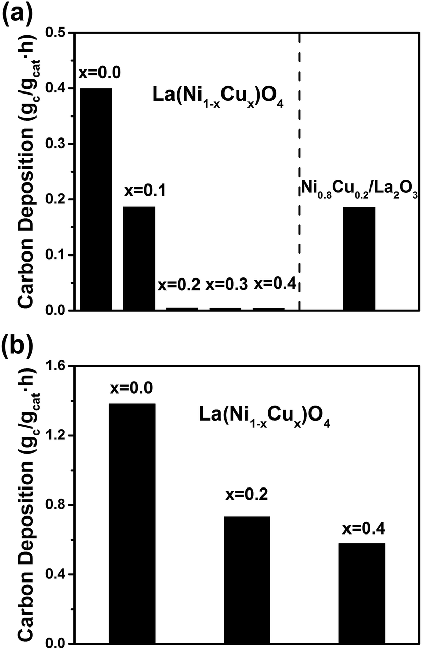 | ||
| Fig. 2 Carbon deposition rates measured by TPO for (a) the DRM reaction, (b) the CH4 decomposition reaction. | ||
3.2. XRD analysis of the fresh, as-reduced and used catalysts
Fig. 3(a) shows the XRD diffraction patterns of fresh La2(Ni1−xCux)O4 catalysts with different x values. All the fresh catalysts consist of a dominant amount of tetragonal La2(NiCu)O4 and a small amount of La2O3. The lattice parameters of the tetragonal La2(Ni1−xCux)O4 unit cell determined from the XRD patterns are listed in Table 1. To further confirm the incorporation of Cu in the perovskite lattice and the formation of La2(Ni1−xCux)O4, the (103) and (110) XRD peaks of the perovskite phase are magnified and shown in Fig. 3(b). The standard XRD peak positions of La2NiO4 ((JCPDS 76-0055)) and La2Ni0.5Cu0.5O4 (JCPDS 80-1075) are shown in Fig. 3(b) for reference purpose. The (103) peak shifts to lower angles while the (110) peak shifts to higher angles with the increase of x. This shift is due to the change in the lattice parameters of the tetragonal La2(Ni1−xCux)O4 unit cell, which is in agreement with the previous report.18 It is seen that as x increases from 0.0 to 0.4, both the lattice parameters and the peak positions of the La2(Ni1−xCux)O4 perovskite phase approach to those of the La2Ni0.5Cu0.5O4 (JCPDS 80-1075), indicating Cu has been incorporated into the B-site of the perovskite. Fig. 3(c) shows the XRD diffraction patterns of the as-reduced La2(Ni1−xCux)O4 catalysts, which are reduced by H2 at 700 °C for 1 h. All the perovskites decompose completely after the reduction. Metallic Ni phase, together with La2O3 and La(OH)3, is identified in the XRD patterns of the as-reduced catalysts. The formation of La(OH)3 may be due to the reaction between La2O3 and moisture. Fig. 3(d) shows the XRD patterns of the used catalysts. After DRM, La2O3 and La(OH)3 turn into La2O2CO3 due to the reaction between La2O3 and CO2. According to Gallego et al.,9,11,19 the La2O3 support also participates in DRM by reacting with CO2 to form La2O2CO3, and La2O2CO3 may react with the surface carbon species formed on the Ni particles to produce CO. Fig. 3(e) shows the magnified XRD peaks of Ni (111) of the as-reduced catalysts with different x values. The Ni (111) peak shifts to lower angles and the lattice parameter decreases from 3.5235 to 3.5553 Å when x increases from 0.0 to 0.4. Thus, the formation of Ni–Cu alloy is confirmed in the x = 0.1–0.4 samples by comparing the lattice parameters with standard ones of Ni (111) (3.5238 Å, JCPDS 04-0850) and NiCu (111) (3.5615 Å, JCPDS 65-7246).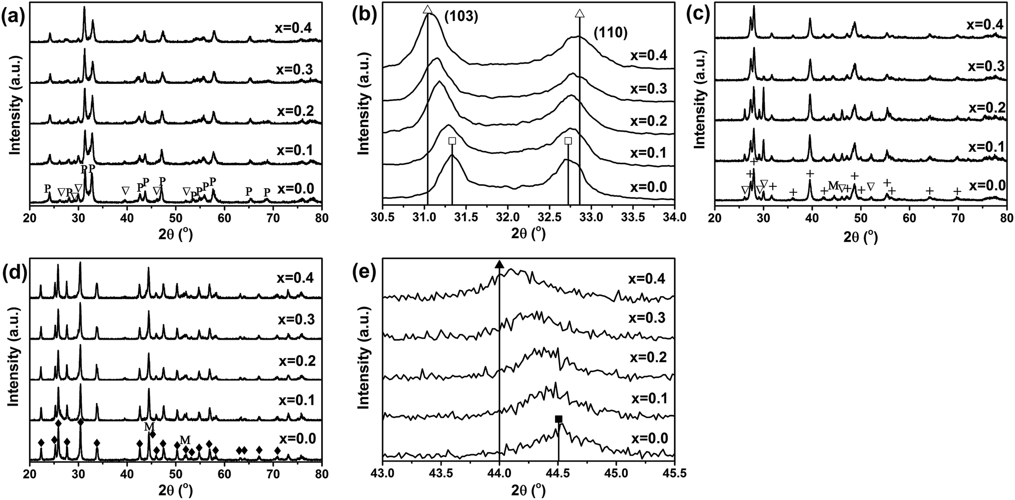 | ||
| Fig. 3 (a) XRD patterns of fresh La2(Ni1−xCux)O4, (b) magnified (103) and (110) peaks of the perovskite La2(Ni1−xCux)O4 phase, (c) XRD patterns of as-reduced La2(Ni1−xCux)O4, (d) XRD patterns of used La2(Ni1−xCux)O4, and (e) magnified Ni (111) peaks of the as-reduced La2(Ni1−xCux)O4 (P – perovskite phase referring to JCPDS 76-0055, ▽ – La2O3 referring to JCPDS 73-2141, + – La(OH)3 referring to JCPDS 36-1481, M – the Ni phase referring to JCPDS 04-0850, ◆ – La2O2CO3 referring to JCPDS 84-1963, □ – standard La2NiO4 peak position from JCPDS 76-0055, △ – standard La2Ni0.5Cu0.5O4 peak position from JCPDS 80-1075, ■ – standard Ni peak position from JCPDS 04-0850 and ▲ – standard NiCu peak position from JCPDS 65-7246). | ||
3.3. TPR profiles of the fresh catalysts
The TPR profiles of the fresh La2(Ni1−xCux)O4 catalysts with different x values are shown in Fig. 4. All the catalysts are completely reduced below 700 °C, which is in agreement with the above XRD analyses. The TPR profile of La2NiO4 agrees well with that reported by Liu et al.,10 in which the peak centered at about 400 °C is attributed to the reduction of NiO and the peak in the range of 450–680 °C is assigned to the reduction of La2NiO4. As we can see, the peak related to the reduction of perovskites shifts to lower temperatures as the substitution degree of Cu increases, indicating that the incorporation of Cu increases the reducibility of the perovskites. | ||
| Fig. 4 TPR profiles of the fresh La2(Ni1−xCux)O4. | ||
3.4. XPS analysis of the used catalysts
Fig. 5(a) shows the XPS spectra of Cu2p for the used La2(Ni1−xCux)O4 samples with x = 0.0, 0.2 and 0.4. As expected, we cannot observe any Cu peaks for the Cu-absent x = 0.0 sample. For the Cu-present x = 0.2 and 0.4 samples, Cu2p3/2 (932.7 eV) and Cu2p1/2 (952.5 eV) are clearly identified. The absence of large satellite peaks indicates the absence of CuO.20 Thus, we conclude that Cu exists in its metallic form. Fig. 5(b) shows the spectra of Ni3p (together with Cu3p). For all three samples, Ni3p can be deconvoluted into Ni3p3/2 (66.2 eV), Ni3p1/2 (68.0 eV) and a satellite peak, indicating the Ni element exists as metallic Ni.21 Both Ni and Cu exist in their metallic forms, indicating that the perovskite precursors decompose completely under the reducing DRM conditions. The composition of the Ni–Cu alloy is determined by the XPS analysis and the results are listed in Table 2. It is worth noting that the atomic ratio of Cu in the Ni–Cu alloy is much larger than the stoichiometric ratio of the La2(Ni1−xCux)O4 precursors. This is because the penetration depth of XPS is very small (1–5 nm).22 Thus, the composition determined by XPS reflects the surface composition of the alloy. The larger surface Cu:Ni atomic ratio indicates an aggressive surface segregation of Cu in the Ni–Cu alloy.
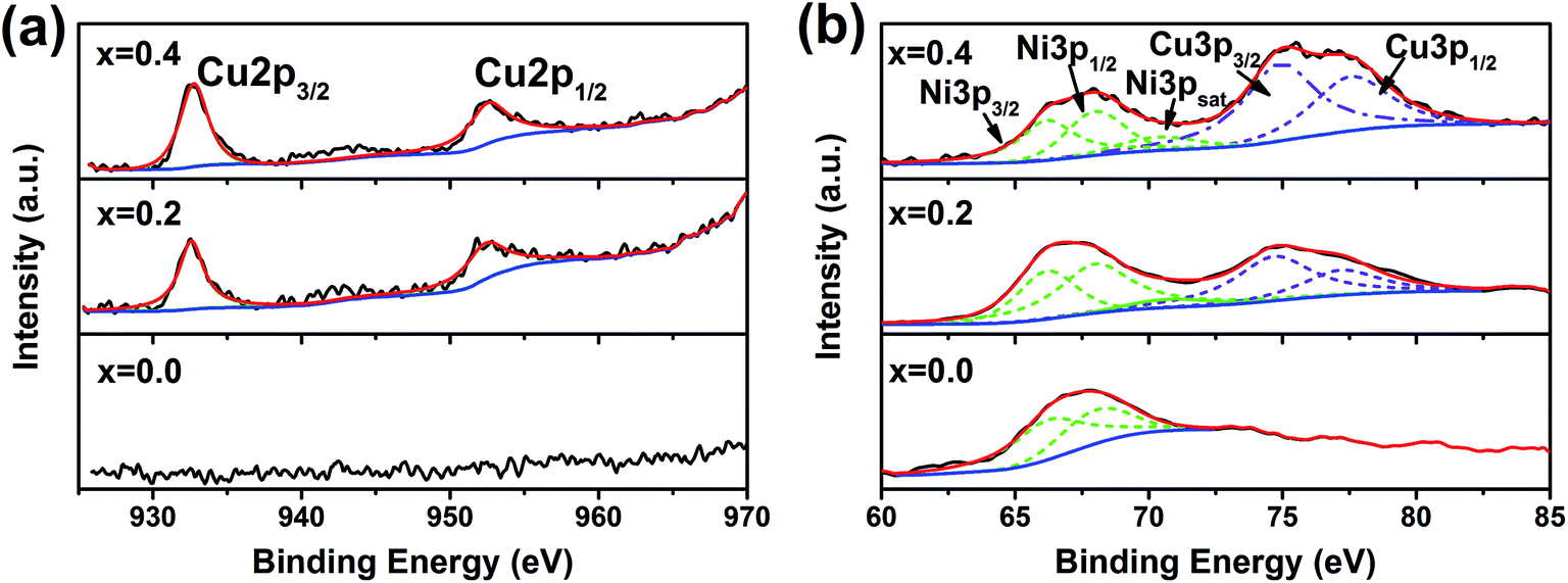 | ||
| Fig. 5 XPS profiles of the used La2(Ni1−xCux)O4 with x = 0.0, 0.2 and 0.4: (a) Cu2p, (b) Ni3p and Cu3p. | ||
| x in La2(Ni1−xCux)O4 (stoichiometry) | x in Ni1−xCux (by XPS) |
|---|---|
| 0.0 | 0.0000 |
| 0.2 | 0.4554 |
| 0.4 | 0.6486 |
3.5. Microstructures of the used catalysts
Fig. 6 shows the SEM images of the used catalysts. Large amount of filamentous carbon can be observed for the La2(Ni1−xCux)O4 samples with x = 0.0, 0.1 and Ni0.8Cu0.2/La2O3, while no carbon can be seen for the x = 0.2–0.4 samples. This is in agreement with Fig. 2(a). | ||
| Fig. 6 SEM images of the used La2(Ni1−xCux)O4 with x = (a) 0.0, (b) 0.1, (c) 0.2, (d) 0.3, (e) 0.4, and (f) Ni0.8Cu0.2/La2O3. | ||
To gain further microstructural information of the used catalysts, TEM analyses were performed and the TEM images are shown in Fig. 7. Metallic particles dispersed on the support can be observed for all the samples. Carbon is present for the x = 0.0, 0.1 samples and Ni0.8Cu0.2/La2O3 but absent for the x = 0.2–0.4 samples, which agrees with Fig. 2(a) and 6. The insets of Fig. 7 show the lateral size distributions of Ni particles which are statistically analyzed over more than 150 particles. It is interesting to note that although the reduced La2(Ni1−xCux)O4 catalysts show significant differences in carbon deposition, the size distributions (0–40 nm) of the metal particles are very similar. On the other hand, the impregnated Ni0.8Cu0.2/La2O3 shows a more disperse metal particle distribution (0–90 nm). The phenomenon that the metallic particle size of impregnated samples is larger than that of the reduced perovskites agrees with other reports.8–11
 | ||
| Fig. 7 TEM images of the used La2(Ni1−xCux)O4 with x = (a) 0.0, (b) 0.1, (c) 0.2, (d) 0.3, (e) 0.4, and (f) Ni0.8Cu0.2/La2O3. | ||
4. Discussion
According to our results, the reduced La2(Ni0.8Cu0.2)O4 shows the optimal catalytic performances with high catalytic activity and significantly improved carbon resistance.Obviously, the reduced La2(Ni0.8Cu0.2)O4 shows better catalytic performance than the impregnated Ni0.8Cu0.2/La2O3. According to Fig. 7, the metallic particle size of the x = 0.2 sample is smaller than that of the impregnated Ni0.8Cu0.2/La2O3. It is generally accepted4,23 that the nucleation of the CNTs is through a dissolution–precipitation mechanism. Carbon, which has a high solubility in the nickel lattice, may dissolve into the nickel crystal and precipitate after supersaturation. According to Bengaard et al.,24 large nickel particles favor graphite nucleation, since a graphite nucleus needs to be large enough to be stable. Thus, the large metallic particles of the impregnated Ni0.8Cu0.2/La2O3 lead to severe carbon deposition. Similar results were reported by Gallego et al.11
However, it is interesting to note that although the metal particles show similar distribution (see the insets of Fig. 7), the reduced La2(Ni1−xCux)O4 catalysts show significant differences in carbon deposition. Thus, we cannot attribute the remarkably improved carbon resistance of the x = 0.2–0.4 samples to the size effects of the metal particles. We have confirmed the surface segregation of Cu in the Ni–Cu particles of the reduced La2(Ni1−xCux)O4 catalysts (see Table 2). The surface segregation of Cu in Ni–Cu has also been widely reported.25–30 Moreover, Zhu et al. reported25 that the distribution of Cu on the Ni–Cu particle surface is not uniform; Cu tends to segregate at corners and edges of the particle and both Ni and Cu tend to have neighbors of the same element. Thus, a cage-like structure of Cu forms on the surface of the Ni core and divides the surface of Ni ensembles into small areas. The small areas of Ni should be too small for the formation of stable graphite nucleus, thus suppresses the carbon deposition. Nevertheless, Cu is reported to be inert for CH4 adsorption and dissociation.31,32 Further increase of x above 0.2 leads to reduced Ni-exposure on the metal surface, resulting in reduced catalytic activity.
5. Conclusions
La2(Ni1−xCux)O4 catalyst precursors were synthesized by glycine sol–gel self-combustion method. The reduced La2(Ni0.8Cu0.2)O4 shows optimal performance with negligible carbon deposition, and the conversions of CH4 and CO2 are 73% and 80%, respectively. The remarkably improved carbon resistance of the reduced La2(Ni0.8Cu0.2)O4 is attributed to: (1) the smaller metallic particles of the reduced perovskite as compared with those of the impregnated catalyst; (2) the cage-like structure of surface segregated Cu, which divides the surface of Ni ensembles into small areas and suppresses the formation of stable graphite nucleus. Thus, the perovskite La2(Ni0.8Cu0.2)O4 is a promising catalyst precursor for DRM.Conflicts of interest
There are no conflicts to declare.Acknowledgements
This work is supported by the National Natural Science Foundation of China (Grant No. 21427804).References
- I. Wender, Fuel Process. Technol., 1996, 48, 189–297 CrossRef CAS
.
- D. L. Trimm, Catal. Rev.: Sci. Eng., 1977, 16, 155–189 CAS
- Y. Vafaeian, M. Haghighi and S. Aghamohammadi, Energy Convers. Manage., 2013, 76, 1093–1103 CrossRef CAS
- D. L. Trimm, Catal. Rev., 1977, 16, 155–189 CAS
- C. H. Bartholomew, Catal. Rev., 2007, 24, 67–112 Search PubMed
- M. C. J. Bradford and M. A. Vannice, Catal. Rev., 1999, 41, 1–42 CAS
- D. Pakhare and J. Spivey, Chem. Soc. Rev., 2014, 43, 7813–7837 RSC
- J. Rynkowski, P. Samulkiewicz, A. K. Ladavos and P. J. Pomonis, Appl. Catal., A, 2004, 263, 1–9 CrossRef CAS
- G. S. Gallego, F. Mondragón, J.-M. Tatibouët, J. Barrault and C. Batiot-Dupeyrat, Catal. Today, 2008, 133, 200–209 CrossRef
- B. S. Liu and C. T. Au, Catal. Lett., 2003, 85, 165–170 CrossRef CAS
- G. S. Gallego, F. Mondragón, J. Barrault, J.-M. Tatibouët and C. Batiot-Dupeyrat, Appl. Catal., A, 2006, 311, 164–171 CrossRef CAS
- H. Liu, C. Y. Guan, X. Li, L. Y. Cheng, J. B. Zhao, N. H. Xue and W. P. Ding, ChemCatChem, 2013, 5, 3904–3909 CrossRef CAS
- H. W. Chen, C. Y. Wang, C. H. Yu, L. T. Tseng and P. H. Liao, Catal. Today, 2004, 97, 173–180 CrossRef CAS
- J. H. Lee, E. G. Lee, O. S. Joo and K. D. Jung, Appl. Catal., A, 2004, 269, 1–6 CrossRef CAS
- R. Pereñíguez, V. M. González-DelaCruz, J. P. Holgado and A. Caballero, Appl. Catal., B, 2010, 93, 346–353 CrossRef
- S. Keav, S. Matam, D. Ferri and A. Weidenkaff, Catalysts, 2014, 4, 226–255 CrossRef
- G. Sierra Gallego, F. Mondragón, J.-M. Tatibouët, J. Barrault and C. Batiot-Dupeyrat, Catal. Today, 2008, 133–135, 200–209 CrossRef CAS
- K. K. Singh, P. Ganguly and C. N. R. Rao, Mater. Res. Bull., 1982, 17, 493–500 CrossRef CAS
- G. N. Sierra Gallego, C. Batiot-Dupeyrat, J. L. Barrault and F. Mondragón, Ind. Eng. Chem. Res., 2008, 47, 9272–9278 CrossRef CAS
- A. Galtayries and J. P. Bonnelle, Surf. Interface Anal., 1995, 23, 171–179 CrossRef CAS
- F. U. Hillebrecht, J. C. Fuggle, P. A. Bennett, Z. Zołnierek and C. Freiburg, Phys. Rev. B: Condens. Matter Mater. Phys., 1983, 27, 2179–2193 CrossRef CAS
- C. Tang, Y. Kwon and J. Leckie, J. Membr. Sci., 2007, 287, 146–156 CrossRef CAS
- F. Abild-Pedersen, J. K. Nørskov, J. R. Rostrup-Nielsen, J. Sehested and S. Helveg, Phys. Rev. B: Condens. Matter Mater. Phys., 2006, 73, 115419 CrossRef
- H. S. Bengaard, J. K. Nørskov, J. Sehested, B. S. Clausen, L. P. Nielsen, A. M. Molenbroek and J. R. Rostrup-Nielsen, J. Catal., 2002, 209, 365–384 CrossRef CAS
- L. Zhu and A. E. DePristo, J. Catal., 1997, 167, 400–407 CrossRef CAS
- D. S. Mainardi and P. B. Balbuena, Langmuir, 2001, 17, 2047–2050 CrossRef CAS
- S. N. Yee, T. T. Tsong and S. B. McLane, Surf. Sci., 1979, 84, 31–53 CrossRef
- P. R. Webber, C. E. Rojas, P. J. Dobson and D. Chadwick, Surf. Sci., 1981, 105, 20–40 CrossRef CAS
- F. J. Kuijers and V. Ponec, Surf. Sci., 1977, 68, 294–304 CrossRef CAS
- H. H. Brongersma, M. J. Sparnaay and T. M. Buck, Surf. Sci., 1978, 71, 657–678 CrossRef CAS
- R. J. Gorte, S. Park, J. M. Vohs and C. Wang, Adv. Mater., 2000, 12, 1465–1469 CrossRef CAS
- T.-J. Huang and S.-Y. Jhao, Appl. Catal., A, 2006, 302, 325–332 CrossRef CAS
| This journal is © The Royal Society of Chemistry 2017 |