DOI:
10.1039/C7RA08002F
(Paper)
RSC Adv., 2017,
7, 42891-42899
Electromagnetic wave absorption polyimide fabric prepared by coating with core–shell NiFe2O4@PANI nanoparticles
Received
20th July 2017
, Accepted 21st August 2017
First published on 5th September 2017
Abstract
The nickel ferrite@polyaniline/polyimide (NiFe2O4@PANI/PI) fabric was prepared by coating the PI fabric with core–shell NiFe2O4@PANI nanoparticles to obtain an excellent microwave absorption performance. Firstly, a microwave absorbing agent was fabricated by dispersing the pre-synthesized core–shell NiFe2O4@PANI nanoparticles into epoxy monomer, in which the covalent bonding between epoxy groups and amine groups from PANI made them uniformly disperse. Then the agent was coated on to the PI fabric to a thickness of 0.12 mm. The results of field effect-transmission electron microscopy and scanning electron microscopy demonstrated the core–shell structure of NiFe2O4@PANI and the composite structure of the NiFe2O4@PANI/PI fabric. The resultant fabric possessed a high microwave attenuation property with a minimum reflection loss value of −19.2 dB (>90% attenuation) at 16.1 GHz and the effective absorption bandwidth was 5.1 GHz. This high performance was attributed to the uniform dispersion of core–shell NiFe2O4@PANI nanoparticles, better impedance matching and intensive synergistic effect between dielectric loss caused by the PANI shell and magnetic loss from the NiFe2O4 core. The favorable flexibility, processability and high tensile properties gave the composite fabric a long service time under pressure or foldable conditions. Furthermore, this process was environmentally friendly as no organic solvent was used in the whole process and the NiFe2O4@PANI/PI fabric could potentially be applied in microwave absorbing fields.
1. Introduction
The electromagnetic (EM) wave pollution from the proliferation of widespread electronics and instruments not only interrupts the usual functions of electronic devices but also influences people's health. Therefore, EM wave pollution has been a major concern and the worldwide demand for EM shielding textiles in the electronic and military industries as well as for the use of protective garments has increased dramatically because of their popular light-weight and flexible features.1–4 According to the mechanism of EM shielding, EM shielding textiles should have the capability of reflection or absorption. Currently, to reflect, those fabrics are mainly prepared by combining fabrics with metals (copper, gold, nickel, silver)5–9 or metallic compounds10–12 to obtain excellent electrical conductivity, which leads to high EM shielding effectiveness; however, their applications are limited because of high processing costs, heavy weight and secondary pollution. To give absorption properties, the composite fabrics should have dielectric and/or magnetic loss which may be supplied using coating materials possessing high permittivity or permeability, for example, carbon materials (carbon nanotubes (CNTs), carbon fibers, carbon black, graphene, graphite),13–17 conductive polymers (polyaniline (PANI), polypyrrole),18–20 magnetic particles (iron(II,III) (Fe3O4), cobalt(II,III) oxide (Co3O4), cobalt ferrite (CoFe2O4), nickel ferrite (NiFe2O4), iron(III) oxide (Fe2O3), carbonyl iron)21–26 and dielectric/magnetic hybrid particles,16 all of which allow the EM energy to be attenuated in the absorbing medium. Nevertheless, many problems have not been solved yet such as poor absorption capacity, narrow absorption band and agglomeration effects from the EM wave absorbing fillers.
Using microwave theory,27 the attenuation of EM wave energy can be accomplished by the reflection of the material surface, the absorption and the multiple internal reflections from the material itself. The entire absorption is an ideal method to attenuate the EM wave energy and now it can be achieved by improving the impedance matching and enhancing dielectric and magnetic loss. NiFe2O4 has already shown an unparalleled application potential in the field of EM wave absorption because of its low production cost, high permeability and permittivity, but its homogenous dispersion in resins is difficult to realize because of its poor interfacial compatibility/bonding.27–29 Surface modification is a common method to solve this dispersion problem through surfactants30 and polymers.31 PANI has also been considered as an ideal EM wave absorbing material in coordination with the dielectric loss and improves the dispersion of fillers because of the presence of amine and imine groups in its structure.19,32,33 Additionally, epoxy resin is usually applied to complement the intrinsic characteristics of PANI as an EM wave absorbing matrix on account of its low cost, good chemical, mechanical and thermal stabilities.34 Thus, selecting PANI as a medium to make core–shell NiFe2O4@PANI nanoparticles, can not only improve the EM absorbing performance, but also solve the nanoparticles' dispersion problem in epoxy resin because of the chemical bonding of epoxy groups with amine groups.
In this research, polyimide (PI) fabric was used as the host substrate and a simple method to prepare the NiFe2O4@PANI/PI EM wave absorbing fabric by incorporating dielectric/magnetic nanoparticles is proposed. The preparation process is shown in Scheme 1. Firstly, the core–shell NiFe2O4@PANI nanoparticles were synthesized using an in situ polymerization method. Secondly, a microwave absorbing agent was prepared by uniformly dispersing them into epoxy monomer because of the formation of covalent bonding between the epoxy groups and the amine groups from PANI. Then this agent was coated and cured on the surface of the PI fabric to obtain resultant fabric (Scheme 2). This novel EM wave absorption fabric was designed by considering better impedance matching and intensive synergistic effect from dielectric loss caused by the PANI shell and magnetic loss by the NiFe2O4 core. The chemical structure, magnetic properties and surface morphologies were investigated using Fourier-transform infrared spectroscopy (FT-IR), X-ray diffraction (XRD), vibrating sample magnetometry (VSM), field effect-transmission electron microscopy (FE-TEM) and scanning electron microscopy (SEM). The EM wave absorption performance, attenuation mechanism, thermal stability and mechanical properties of the resultant fabric are also discussed in detail in this paper.
 |
| | Scheme 1 The preparation route of NiFe2O4@PANI/PI fabric. | |
 |
| | Scheme 2 The related mechanism of preparation. | |
2. Experimental
2.1 Materials
The PI fabric was purchased from Jiangsu Aoshen Hi-tech Materials Co. The NiFe2O4 with an average size of 30 nm was obtained from the Nanjing Emperor Nano Material Co., Ltd. The bisphenol A epoxy monomer (BPA, 2,2-bis(4-glycidyloxyphenyl)propane, DER331) was provided by Adamas Reagent (Switzerland). Aniline (AN, C6H7N) monomer, ammonium persulfate (APS, (NH4)2S2O8) and p-toluene sulfonic acid (PTSA, C7H8O3S) were purchased from Shanghai Chemical Reagent Co., Ltd, China. All chemicals were of analytical grade and were used as received without further purification.
2.2 Preparation of core–shell NiFe2O4@PANI nanoparticles
The core–shell NiFe2O4@PANI nanoparticles were prepared using an in situ polymerization method. Briefly, NiFe2O4 nanoparticles (2.5 g), PTSA (3.8 g) and APS (2.28 g) were added in 100 mL of deionized water at the room temperature with mechanically stirring (300 rpm) for one hour. Then AN monomer (1.9 mL) was added into the previous suspension and mechanically stirred (400 rpm) for 3 h at 0–5 °C in an iced-water bath. Finally the composites were vacuum filtered and washed with a large amount of deionized water, and then dried at room temperature.
2.3 Preparation of NiFe2O4@PANI/PI fabric
The NiFe2O4@PANI/PI fabric was prepared using a coating process. Firstly, the microwave absorbing agent was synthesized by dispersing as-prepared NiFe2O4@PANI nanoparticles (20, 30 and 40 wt%) into BPA and mechanically stirred (200 rpm) for 2 h so that the epoxy monomer would completely wet the NiFe2O4@PANI nanoparticles. Secondly, the curing agent (AN monomer) was added into the previously prepared suspension with a BPA/AN molar ratio of 2![[thin space (1/6-em)]](https://www.rsc.org/images/entities/char_2009.gif) :1, and then mechanically stirred (200 rpm) at 70 °C for 2 h. After that, the microwave absorbing agent was coated by screen on the surface of the PI fabric and then cured at 60 °C for 24 h to obtain the NiFe2O4@PANI/PI fabric. The samples were described as 20NiFe2O4@PANI/PI fabric, 30NiFe2O4@PANI/PI fabric and 40NiFe2O4@PANI/PI fabric based on the different amounts of NiFe2O4@PANI nanoparticles (20, 30 and 40 wt%) used. The 30PANI/PI fabric and 30NiFe2O4/PI fabric were also prepared following the previously mentioned procedures with the 30 wt% filling content for comparison.
:1, and then mechanically stirred (200 rpm) at 70 °C for 2 h. After that, the microwave absorbing agent was coated by screen on the surface of the PI fabric and then cured at 60 °C for 24 h to obtain the NiFe2O4@PANI/PI fabric. The samples were described as 20NiFe2O4@PANI/PI fabric, 30NiFe2O4@PANI/PI fabric and 40NiFe2O4@PANI/PI fabric based on the different amounts of NiFe2O4@PANI nanoparticles (20, 30 and 40 wt%) used. The 30PANI/PI fabric and 30NiFe2O4/PI fabric were also prepared following the previously mentioned procedures with the 30 wt% filling content for comparison.
2.4 Characterization
The chemical structure was determined using FT-IR analysis (Nicolet 6700, Thermo Fisher Scientific) in the spectral range of 4000–400 cm−1, with 4 cm−1 resolution. All of the samples were cut into powder and mixed with potassium bromide. The XRD at λ = 0.1542 nm (D/max 2550, Rigaku, Japan) was used to investigate the crystal structure of samples at room temperature with 2θ ranges from 5° to 80°, at 40 kV, and 200 mA, and a scanning step of 0.02° per second. The magnetic properties were characterized using VSM (Lake Shore Cryotronics, USA) at room temperature. The surface morphologies of the as-prepared NiFe2O4@PANI composites were characterized using FE-TEM (FE Tecnai TF20) with a field-emission gun, operated at an accelerating voltage of 200 kV. The morphologies of the PI fabric before and after coating were observed using SEM (Hitachi TM-1000). The SEM images were obtained in vacuum at a 3000 magnification and at an accelerating voltage of 10 kV. The thermal stability was determined using thermogravimetric analysis (TGA, TG 209 F1, Netzsch, Germany) in a flowing nitrogen (N2) atmosphere with a heating rate of 10 °C min−1, from 50 to 900 °C. The photographs of the flexibility and processability were captured using an optical camera. The tensile tests were carried out using a materials testing machine (H5K-S, Tinius Olsen, USA) according to the Chinese standard GB 9997-88 at 25 °C and 65% relative humidity. Each sample was tested 10 times and the average value was taken as the result. The relative complex permittivity (εr = ε′ − jε′′) and relative complex permeability (μr = μ′ − jμ′′) were tested on a vector network analyzer (Anritsu 37269D, USA) using the wave guide method in the frequency range of 12.4–18.0 GHz. All the test samples were cut into dimensions of 15.9 × 8 × 2 mm3. The reflection loss (RL) coefficients and attenuation constant (α) were calculated according to transmission line theory.
3. Results and discussion
3.1 Structure and magnetic analysis
The chemical structure was verified using FT-IR spectra and these are shown in Fig. 1(a). For the neat PANI, the absorption peaks at 1580 cm−1 and 1497 cm−1 were attributed to the C![[double bond, length as m-dash]](https://www.rsc.org/images/entities/char_e001.gif) C stretching vibration of the quinoid ring skeleton (Q) and the benzenoid ring skeleton (B), respectively. The intensity of these two peaks could give information about the degree of oxidation of the emeraldine form.20 The strong absorption peak at 1127 cm−1 was assigned to the B–Q–B stretching vibration, revealing that the conductive form of PANI was present.35 The peak at 1299 cm−1 was associated to the C–N stretching vibration of the benzene ring. These absorption peaks (1580, 1497, 1299 and 1127 cm−1) were also observed in the spectrum of NiFe2O4@PANI nanoparticles, but had a slight shift (about 3–8 cm−1) compared with the spectrum of neat PANI, suggesting that the surface of the NiFe2O4 was successfully functionalized by the PANI. Additionally, for the cured 30NiFe2O4/epoxy, the absorption peak around 1235 cm−1 was derived from the C–O–C stretching vibration which also presented in the spectrum of the cured 30NiFe2O4@PANI/epoxy. Furthermore, it is worth noting that the terminal epoxy groups were observed at 912 cm−1 in the spectrum of cured 30NiFe2O4/epoxy, but it had nearly disappeared in the spectrum of cured 30NiFe2O4@PANI/epoxy. This result could be explained by the fact that the amine groups with a reactive hydrogen atom from the PANI have reacted with the epoxy groups, which was beneficial to the uniform dispersion of NiFe2O4@PANI nanoparticles in the epoxy resin.
C stretching vibration of the quinoid ring skeleton (Q) and the benzenoid ring skeleton (B), respectively. The intensity of these two peaks could give information about the degree of oxidation of the emeraldine form.20 The strong absorption peak at 1127 cm−1 was assigned to the B–Q–B stretching vibration, revealing that the conductive form of PANI was present.35 The peak at 1299 cm−1 was associated to the C–N stretching vibration of the benzene ring. These absorption peaks (1580, 1497, 1299 and 1127 cm−1) were also observed in the spectrum of NiFe2O4@PANI nanoparticles, but had a slight shift (about 3–8 cm−1) compared with the spectrum of neat PANI, suggesting that the surface of the NiFe2O4 was successfully functionalized by the PANI. Additionally, for the cured 30NiFe2O4/epoxy, the absorption peak around 1235 cm−1 was derived from the C–O–C stretching vibration which also presented in the spectrum of the cured 30NiFe2O4@PANI/epoxy. Furthermore, it is worth noting that the terminal epoxy groups were observed at 912 cm−1 in the spectrum of cured 30NiFe2O4/epoxy, but it had nearly disappeared in the spectrum of cured 30NiFe2O4@PANI/epoxy. This result could be explained by the fact that the amine groups with a reactive hydrogen atom from the PANI have reacted with the epoxy groups, which was beneficial to the uniform dispersion of NiFe2O4@PANI nanoparticles in the epoxy resin.
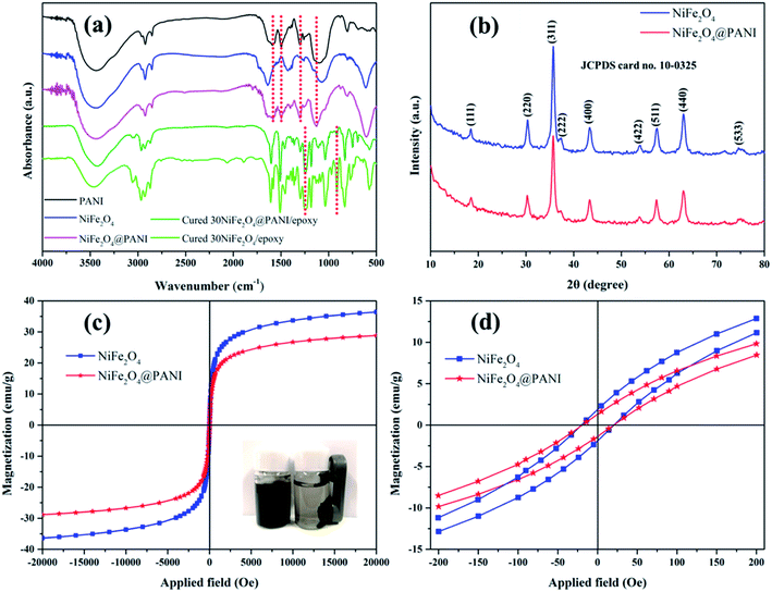 |
| | Fig. 1 (a) FT-IR spectra of PANI, NiFe2O4, NiFe2O4@PANI, cured 30NiFe2O4@PANI/epoxy and cured 30NiFe2O4/epoxy. (b) XRD patterns, (c) magnetization hysteresis loops and (d) the enlarged magnetization hysteresis loops of NiFe2O4, NiFe2O4@PANI. Inset of (c) shows that NiFe2O4@PANI was attracted by a permanent magnet. | |
The XRD patterns of NiFe2O4 and NiFe2O4@PANI nanoparticles are shown in Fig. 1(b). By comparison, it was clearly seen that these peaks of NiFe2O4 and NiFe2O4@PANI nanoparticles had no significant difference except for the intensity and all the diffraction peaks were located at 2θ = 18.64°, 30.49°, 35.85°, 37.55°, 43.58°, 53.11°, 57.58°, 63.21° and 75.09°, corresponding to the (111), (220), (311), (222), (400), (422), (511), (400) and (533) cubic spinel of NiFe2O4 (JCPDS card no. 10-0325), respectively. The spectra of Fig. 1(a) and (b) confirmed the coexistence of NiFe2O4 and PANI and suggest that the introduction of PANI had a negligible influence on the crystalline structure of the NiFe2O4 nanoparticles.26 Additionally, it is believable that the magnetic properties may be conducive to balancing the impedance matching condition between the complex permittivity and complex permeability.16 So the investigation of magnetic properties plays an important role in understanding the EM wave attenuation performance and the magnetic hysteresis loops of NiFe2O4 and NiFe2O4@PANI are shown in Fig. 1(c). As can be seen in Fig. 1(c), both samples exhibited a typical hysteresis loop in their magnetic behavior and the saturation magnetization (Ms) values of NiFe2O4 and NiFe2O4@PANI were 36.4 emu g−1 and 28.9 emu g−1, respectively. Although the Ms value of NiFe2O4@PANI was slightly decreased because of the addition of non-magnetic PANI, on basis of research investigation,16,25 it is believed that the effects of dispersion improvement and impedance matching condition originating from PANI are important in enhancing the microwave absorption. The inset image of Fig. 1(c) shows the magnetic performance of NiFe2O4@PANI nanoparticles, which could be attracted when a magnet was placed beside a bottle filled with NiFe2O4@PANI nanoparticles dispersed in deionized water. Furthermore, the magnetic hysteresis loops of both samples showed an S-like shape and the enlarged magnetization hysteresis loops are shown in Fig. 1(d), which demonstrates that the NiFe2O4@PANI maintained the same coercivity (Hc) of the NiFe2O4 nanoparticles, suggesting that the anisotropic energy was favorable for the enhancement of the EM wave attenuation performance.36–38
3.2 Morphological analysis
The FE-TEM images of NiFe2O4@PANI nanoparticles are shown in Fig. 2(a) and (b). Both FE-TEM images indicate that the hybrid consists of evenly dispersed NiFe2O4 with an average diameter of about 30 nm in the PANI matrix. The selected area electron diffraction pattern [inset in Fig. 2(a)] exhibits polycrystalline diffraction rings with many obvious diffraction spots, indicating the highly crystalline structure of NiFe2O4. The bright amorphous layer depicted in Fig. 2(b) is distinctly different from the NiFe2O4 cores, revealing that the noncrystal PANI layer was formed on the surface of the NiFe2O4 nanoparticles. Fig. 2(c) displays the surface morphologies of the fabrics before and after coating. It is clearly observed that an even film was coated on the PI fabric surface. The coating thickness was measured using an electronic digital display micrometer and was about 0.12 mm. At a higher magnification [Fig. 2(d)], the relatively smooth surface indicates that NiFe2O4@PANI nanoparticles were evenly dispersed in a microwave absorbing agent, which resulted from the covalent bonding between the epoxy groups and the amine groups from PANI, suggesting that there was no “dead area” of invalid microwave absorbing components.
 |
| | Fig. 2 (a) and (b) FE-TEM images of NiFe2O4@PANI nanoparticles. (c) and (d) SEM micrographs of 30NiFe2O4@PANI/PI fabric. | |
3.3 Microwave absorption properties
As far as is known, the EM energy can be attenuated by the reflection of the material surface, the absorption and the multiple internal reflections from the absorber itself when exposed beneath the EM wave irradiation. The integral EM wave absorption performance of the composite fabrics can be determined by the RL values, which were simulated from the measured relative complex permittivity and permeability values. According to transmission line theory, the RL values were calculated by the following equations:39| |
 | (1) |
where Zin is the input impedance of the absorption layer and Z0 is the impedance of free space, which can be expressed as:| |
 | (2) |
| |
 | (3) |
where εr and μr are the complex relative permittivity and permeability of the absorption layer, respectively, ε0 and μ0 are the complex relative permeability and permittivity of free space, respectively, d is the thickness, f is the frequency of the EM wave, and c is the velocity of light (3 × 10⁸ m s−1). The three-dimensional (3D) contour maps of RL with the correlation of thickness and frequency are shown in Fig. 3(a)–(e). It is clearly seen that the minimum RL values had a tendency to a lower frequency range with increasing thickness. It is believed that the different ratios of NiFe2O4@PANI nanoparticles would lead to distinguishable dielectric/magnetic loss, and would also influence EM wave absorption performance. In Fig. 3(a)–(c), it is seen that the minimum RL values of prepared 20NiFe2O4@PANI/PI, 30NiFe2O4@PANI/PI and 40NiFe2O4@PANI/PI fabric were −9.1 dB, −19.2 dB and −11.3 dB, respectively. Meanwhile, the 30NiFe2O4@PANI/PI fabric exhibited the highest EM wave absorption performance with over 90% attenuation at 16.1 GHz and the effective absorption bandwidth below −10 dB was 5.1 GHz with a thickness of only 1.5 mm, which could be explained reasonably by the effective medium theory of Maxwell-Garnett.40 Furthermore, for comparison, the EM properties of the 30PANI/PI fabric [Fig. 3(d)] and 30NiFe2O4/PI fabric [Fig. 3(e)] were also measured and they exhibited poor EM wave absorption properties and the minimum RL values were only −7.1 dB and −6.3 dB, respectively. Because the lower the RL, the better is the EM wave absorption,27 these results demonstrated that the 30NiFe2O4@PANI/PI fabric possessed a higher EM wave absorption performance than the 30PANI/PI fabric and 30NiFe2O4/PI fabric, which could be explained by the fact that the core–shell NiFe2O4@PANI nanoparticles were beneficial for improving EM wave absorption performance because of the intensive synergistic effect of dielectric/magnetic loss and the increasing for the number of interfaces.
 |
| | Fig. 3 3D contour maps of RL for (a) 20NiFe2O4@PANI/PI fabric, (b) 30NiFe2O4@PANI/PI fabric, (c) 40NiFe2O4@PANI/PI fabric, (d) 30PANI/PI fabric and (e) 30NiFe2O4/PI fabric. (f) Frequency dependence of the attenuation constants. | |
Furthermore, the EM wave attenuation ability inside the materials is related to the attenuation constant. Thus, to further analyse the EM wave absorption performance, the attenuation constant was expressed according to transmission line theory as:41
| |
 | (4) |
where
ε′ and
ε′′ are the real and imaginary parts of complex relative permittivity,
μ′ and
μ′′ are the real and imaginary parts of the complex relative permeability,
f is the frequency of EM wave, and
c is the velocity of light.
Fig. 3(f) shows the curves of the calculated attenuation constant (
α) and it is evident that the
α value of 30NiFe
2O
4@PANI/PI fabric was higher than those of other composite fabrics and this is basically consistent with the results of RL, also suggesting that there is a higher EM wave attenuation performance.
It is known that the prominent EM wave attenuation performance may be derived from three factors: a suitable impedance matching condition, the strong dielectric loss and magnetic loss. As far as is known, the storage capability of the electric and magnetic energy is related to the real parts (ε′ and μ′) of the complex permittivity and permeability, whereas the dissipation loss capability can be determined by the imaginary parts (ε′′ and μ′′). The dielectric and magnetic loss tangent (tanδE = ε′′/ε′, tanδM = μ′′/μ′) may provide a measure of the amount of EM wave energy loss compared with the amount of EM wave energy storage, respectively. Therefore, in order to determine the possible attenuation mechanism of the EM wave energy, the relative complex permittivity, relative complex permeability, dielectric and magnetic dissipation factors of the various samples were measured in the 12.4–18.0 GHz frequency range using the wave guide method and the results are shown in Fig. 4(a)–(e). As shown in Fig. 4(a) and (b), the ε′ and ε′′ values of all the samples were found to decrease with increasing frequency in the investigated range, which displayed a similar frequency dispersion behavior to certain carbon materials, for example, carbon nanocoils, CNTs and carbon fibers.42 In Fig. 4(a)–(c), it was observed that the ε′, ε′′ and tanδE values of 30NiFe2O4@PANI/PI fabric were higher than those of 30NiFe2O4/PI fabric, suggesting that 30NiFe2O4@PANI/PI fabric had a better electrical energy storage/loss capability and that the PANI shell played a vital role in enhancing dielectric loss. These results could be attributed to the plentiful interfaces and interfacial polarization that occurred between the NiFe2O4 surface and the PANI layer. In addition, compared with the 30PANI/PI fabric, the ε′ and ε′′ values of 30NiFe2O4@PANI/PI fabric were lower, but the added magnetic loss was favourable for improving the EM wave absorption performance, and furthermore, the 30NiFe2O4@PANI/PI fabric displayed a better impedance matching condition, allowing the EM wave to propagate into the material sufficiently while avoiding the strong reflection.43,44
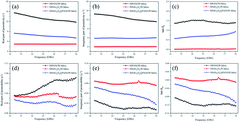 |
| | Fig. 4 (a) Real part, (b) imaginary part and (c) dielectric tangent loss of relative complex permittivity, (d) real part, (e) imaginary part and (f) magnetic tangent loss of relative complex permeability for the 30PANI/PI fabric, the 30NiFe2O4/PI fabric and the 30NiFe2O4@PANI/PI fabric. | |
Fig. 4(d)–(f) show the μ′, μ′′ and tanδM values of 30PANI/PI fabric, 30NiFe2O4/PI fabric and 30NiFe2O4@PANI/PI fabric. These curves demonstrated a specific fluctuation from 12.4 to 18.0 GHz, which might be attributed to the small size effect and the confinement effect.45 In Fig. 4(d), the μ′ values of 30NiFe2O4/PI fabric and 30NiFe2O4@PANI/PI fabric were around 1.02, and they first increased and then decreased slightly with the increasing frequency. However, for μ′′ in Fig. 4(e), the values were around 0 and then decreased slightly with the increasing frequency. The negative μ′′ value demonstrated that the magnetic energy was mainly radiated outwards. It is known that the magnetic loss mainly originates from several aspects: hysteresis loss, eddy current loss, domain wall resonance loss (multi-domain materials), natural resonance and exchange resonance loss.46 The weak peak which appeared at 15.2–18.0 GHz in Fig. 4(f) corresponded to the exchange resonance loss. However, the NiFe2O4 nanoparticles with a size of about 30 nm used in this study were usually regarded as single domain materials and the hysteresis loss is negligible in a weak field. The natural resonance loss can be described by the following equation:47
where
Ha is the anisotropic energy, |
K1| is the anisotropic coefficient and
Ms is the saturation magnetization. As depicted in
Fig. 1(b), the
Ms value of NiFe
2O
4@PANI nanoparticles was lower than that of NiFe
2O
4 nanoparticles, demonstrating a higher anisotropic energy for NiFe
2O
4@PANI nanoparticles, which was advantageous for enhancing the EM wave attenuation performance especially at a high frequency. Furthermore, to estimate the eddy current loss of the 30NiFe
2O
4@PANI/PI fabric, the
f−1(
μ′)
−2μ′′ values were simulated and are shown in
Fig. 5(a). If the RL values can be caused by the eddy current loss, the
f−1(
μ′)
−2μ′′ values will incline to constant when the frequency varies.
21 In
Fig. 5(a), the
f−1(
μ′)
−2μ′′ of 30NiFe
2O
4@PANI/PI fabric approximated to a constant, revealing that the 30NiFe
2O
4@PANI/PI fabric possessed the eddy current loss effect for the EM wave energy dissipation. As discussed previously, the possible EM wave attenuation mechanism of 30NiFe
2O
4@PANI/PI fabric is shown in
Fig. 5(b). In brief, the 30NiFe
2O
4@PANI/PI fabric inherited dielectric and magnetic properties from the
in situ polymerized core–shell NiFe
2O
4@PANI nanoparticles. It is believed that the more uniform the dispersion of core–shell NiFe
2O
4@PANI nanoparticles, the better the impedance matching, and the intensive synergistic effect of dielectric loss caused by PANI shell and the magnetic loss from the NiFe
2O
4 core could contribute to the improvement of the EM wave absorbing performance.
 |
| | Fig. 5 (a) Frequency dependence of the f−1(μ′)−2μ′′ values for 30PANI/PI fabric, 30NiFe2O4/PI fabric and 30NiFe2O4@PANI/PI fabric. (b) Scheme of the possible EM wave attenuation mechanism. | |
3.4 Thermal stability and mechanical properties
Fig. 6(a) shows the degradation curves of PI, NiFe2O4@PANI nanoparticles, 30NiFe2O4@PANI/PI and cured epoxy resin. Because the 30NiFe2O4@PANI/PI fabric had the highest EM wave absorption performance, it was chosen for use in the following tests. As shown in Fig. 6(a), for the PI fabric, the first weight loss at 200–230 °C might be assigned to the decomposition of oligomers and the second decomposition process (550–700 °C) could be attributed to the disconnection of the PI chains. For the 30NiFe2O4@PANI/PI fabric, two weight loss steps at 300–500 °C and 550–700 °C were observed in the measured temperature range, which were from the decomposition of the cured epoxy resin and the PI fabric, respectively. Nevertheless, the decomposition of PANI chains in the curve of 30NiFe2O4@PANI/PI was not distinct, which was because of the relatively small amount of PANI coated on the NiFe2O4 surface. The residual components at 900 °C, of PI, NiFe2O4@PANI nanoparticles, 30NiFe2O4@PANI/PI and cured epoxy resin were 49.1%, 66.7%, 39.9% and 4.8%, respectively, demonstrating that the mass content of NiFe2O4@PANI nanoparticles in the 30NiFe2O4@PANI/PI fabric was about 16.7 wt%.
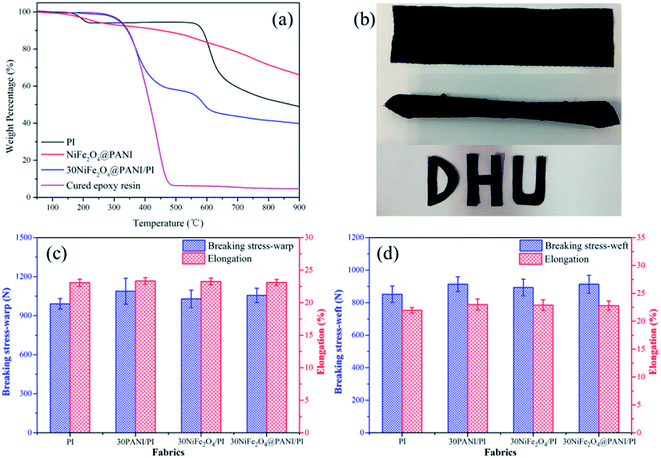 |
| | Fig. 6 (a) TGA curves of PI, NiFe2O4@PANI, 30NiFe2O4@PANI/PI and cured epoxy resin. (b) Photographs of the flexibility and processability. Tensile properties of fabrics before and after different coatings in the warp direction (c) and the weft direction (d). | |
Furthermore, the mechanical properties were evaluated using the flexibility, processability and tensile properties tests at 25 °C and 65% relative humidity. As shown in Fig. 6(b), a large strip (20 cm × 5 cm) of the as-fabricated 30NiFe2O4@PANI/PI fabric could be freely twisted and directly processed into the desired shapes. Fig. 6(c) and (d) show the tensile properties of various samples in the warp and weft directions. Compared with the neat PI fabric, the breaking stress and elongation of coating fabric increased by about 5–10%, which originated from the adhesion of epoxy resin between yarn and yarn, indicating that the preparation process could retain or even increase the mechanical properties from the PI fabric. Thus, such remarkable flexibility, processability and high tensile properties would allow the as-fabricated composite fabric to work for a long time work under pressure or as foldable systems.
4. Conclusions
In summary, the NiFe2O4@PANI/PI EM wave absorbing fabric with incorporated dielectric/magnetic nanoparticles was successfully fabricated and the coated fabric inherited dielectric and magnetic properties from the in situ polymerized core–shell NiFe2O4@PANI nanoparticles. The FT-IR results were used to interpret the formation mechanism of the microwave absorbing agent. FE-TEM results indicated that the PANI layer was formed on the NiFe2O4 surface. SEM images showed a uniform coating of the microwave absorption agent on PI fabric. The studies of relative permittivity and relative permeability indicated that the better impedance matching and the intensive synergistic effect between dielectric loss causing PANI shell and magnetic loss from the NiFe2O4 core contributed to the improvement of the EM wave attenuation performance. The minimum RL value of 30NiFe2O4@PANI/PI fabric was −19.2 dB (>90% attenuation) at 16.1 GHz and the effective absorption bandwidth was 5.1 GHz with a thickness of only 1.5 mm, which made the composite fabric an attractive candidate for EM wave protective garments. Furthermore, the favorable mechanical properties gave the composite fabric for a long service time under pressure or foldable conditions.
Conflicts of interest
There are no conflicts to declare.
Acknowledgements
The research was supported by National Natural Science Foundation of China (No. 51403032).
References
- W. L. Song, L. Z. Fan, Z. L. Hou, K. L. Zhang, Y. Ma and M. S. Cao, J. Mater. Chem. C, 2017, 5, 2432–2441 RSC.
- A. Haji, R. S. Rahbar and A. M. Shoushtari, Appl. Surf. Sci., 2014, 311, 593–601 CrossRef CAS.
- S. T. Hsiao, C. C. Ma, W. H. Liao, Y. S. Wang, S. M. Li, Y. C. Huang, R. B. Yang and W. F. Liang, ACS Appl. Mater. Interfaces, 2014, 6, 10667–10678 CAS.
- K. Cheng, S. Ramakrishna and K. Lee, Composites, Part A, 2000, 31, 1039–1045 CrossRef.
- Y. Lu, L. Xue and F. Li, Appl. Surf. Sci., 2011, 257, 3135–3139 CrossRef CAS.
- D. Yu, W. Li, W. Wang and J. Zhang, Fibers Polym., 2015, 16, 23–30 CrossRef CAS.
- S. Mu, H. Xie, W. Wang and D. Yu, Appl. Surf. Sci., 2015, 353, 608–614 CrossRef CAS.
- M. S. Ozen, E. Sancak, N. Soin, T. H. Shah and E. Siores, J. Text. Inst., 2015, 107, 912–922 CrossRef.
- S. Bi, H. Zhao, L. Hou and Y. Lu, Appl. Surf. Sci., 2017, 419, 465–475 CrossRef CAS.
- M. Ramesan, Polym. Eng. Sci., 2014, 54, 438–445 CAS.
- X.-S. Hu, Y. Shen, L.-H. Xu, L.-M. Wang, L.-s. Lu and Y.-t. Zhang, Appl. Surf. Sci., 2016, 385, 162–170 CrossRef CAS.
- C. Y. Lee, D. E. Lee, C. K. Jeong, Y. K. Hong, J. H. Shim, J. Joo, M. S. Kim, J. Y. Lee, S. H. Jeong and S. W. Byun, Polym. Adv. Technol., 2002, 13, 577–583 CrossRef CAS.
- Y. Yang, M. C. Gupta, K. L. Dudley and R. W. Lawrence, Nano Lett., 2005, 5, 2131–2134 CrossRef CAS PubMed.
- C. Feng, X. Liu, Y. Sun, C. Jin and Y. Lv, RSC Adv., 2014, 4, 22710–22715 RSC.
- S. Das, G. Nayak, S. Sahu, P. Routray, A. Roy and H. Baskey, J. Eng., 2014, 2014 Search PubMed.
- J. Fang, Z. Chen, W. Wei, Y. Li, T. Liu, Z. Liu, X. Yue and Z. Jiang, RSC Adv., 2015, 5, 50024–50032 RSC.
- Z. Lu, L. Ma, J. Tan, H. Wang and X. Ding, Nanoscale, 2016, 8, 16684–16693 RSC.
- M. S. Kim, H. K. Kim, S. W. Byun, S. H. Jeong, Y. K. Hong, J. S. Joo, K. T. Song, J. K. Kim, C. J. Lee and J. Y. Lee, Synth. Met., 2002, 126, 233–239 CrossRef CAS.
- X. D. Yang, K. Q. Lei and J. Y. Hu, Russ. J. Appl. Chem., 2014, 87, 909–915 CrossRef CAS.
- D. Chen, Y. E. Miao and T. Liu, ACS Appl. Mater. Interfaces, 2013, 5, 1206–1212 CAS.
- J. Wang, H. Zhou, J. Zhuang and Q. Liu, Phys. Chem. Chem. Phys., 2015, 17, 3802–3812 RSC.
- Z. Guo, S. E. Lee, H. Kim, S. Park, H. T. Hahn, A. B. Karki and D. P. Young, Acta Mater., 2009, 57, 267–277 CrossRef CAS.
- X. Huang, J. Zhang, Z. Liu, T. Sang, B. Song, H. Zhu and C. Wong, J. Alloys Compd., 2015, 648, 1072–1075 CrossRef CAS.
- J. Feng, F. Pu, Z. Li, X. Li, X. Hu and J. Bai, Carbon, 2016, 104, 214–225 CrossRef CAS.
- W.-p. Li, L.-q. Zhu, J. Gu and H.-c. Liu, Composites, Part B, 2011, 42, 626–630 CrossRef.
- M. Fu, Q. Jiao and Y. Zhao, J. Mater. Chem. A, 2013, 1, 5577–5586 CAS.
- S. P. Pawar, M. Gandi and S. Bose, RSC Adv., 2016, 6, 37633–37645 RSC.
- W. Wang, C. Zang and Q. Jiao, J. Magn. Magn. Mater., 2015, 378, 261–266 CrossRef CAS.
- L. Li, G. Li, R. L. Smith and H. Inomata, Chem. Mater., 2000, 12, 3705–3714 CrossRef CAS.
- X. Wang, C. Zhang, X. Wang and H. Gu, Appl. Surf. Sci., 2007, 253, 7516–7521 CrossRef CAS.
- Y. Kang and T. A. Taton, J. Am. Chem. Soc., 2003, 125, 5650–5651 CrossRef CAS PubMed.
- P. Saini, V. Choudhary, N. Vijayan and R. Kotnala, J. Phys. Chem. C, 2012, 116, 13403–13412 CAS.
- P. Liu, Y. Huang, J. Yan and Y. Zhao, J. Mater. Chem. C, 2016, 4, 6362–6370 RSC.
- W. Yang, S. Yu, R. Sun and R. Du, Ceram. Int., 2012, 38, 3553–3562 CrossRef CAS.
- D. Yu, Y. Wang, T. Hao, W. Wang and B. Liu, J. Ind. Text., 2017, 1–15 CAS.
- J. Guo, X. Wang, P. Miao, X. Liao, W. Zhang and B. Shi, J. Mater. Chem., 2012, 22, 11933–11942 RSC.
- J. Zhu, S. Wei, N. Haldolaarachchige, D. P. Young and Z. Guo, J. Phys. Chem. C, 2011, 115, 15304–15310 CAS.
- X. Li, J. Feng, H. Zhu, C. Qu, J. Bai and X. Zheng, RSC Adv., 2014, 4, 33619–33625 RSC.
- Y. Sun, J. Xu, W. Qiao, X. Xu, W. Zhang, K. Zhang, X. Zhang, X. Chen, W. Zhong and Y. Du, ACS Appl. Mater. Interfaces, 2016, 8, 31878–31886 CAS.
- J. V. Mantese, A. L. Micheli, D. F. Dungan, R. G. Geyer, J. Baker-Jarvis and J. Grosvenor, J. Appl. Phys., 1996, 79, 1655–1660 CrossRef CAS.
- L. Yuan, L. Xiangxuan, L. Rong, W. Wu and W. Xuanjun, RSC Adv., 2015, 5, 8713–8720 RSC.
- Y. Du, W. Liu, R. Qiang, Y. Wang, X. Han, J. Ma and P. Xu, ACS Appl. Mater. Interfaces, 2014, 6, 12997–13006 CAS.
- W.-L. Song, X.-T. Guan, L.-Z. Fan, Y.-B. Zhao, W.-Q. Cao, C.-Y. Wang and M.-S. Cao, Carbon, 2016, 100, 109–117 CrossRef CAS.
- J. Liu, R. Che, H. Chen, F. Zhang, F. Xia, Q. Wu and M. Wang, Small, 2012, 8, 1214–1221 CrossRef CAS PubMed.
- H. Wang, Z. Yan, J. An, J. He, Y. Hou, H. Yu, N. Ma, G. Yu and D. Sun, RSC Adv., 2016, 6, 92152–92158 RSC.
- Y. Wang, W. Wang and D. Yu, Appl. Surf. Sci., 2017, 425, 518–525 CrossRef CAS.
- J.-Q. Zhu, X.-J. Zhang, S.-W. Wang, G.-S. Wang and P.-G. Yin, RSC Adv., 2016, 6, 88104–88109 RSC.
|
| This journal is © The Royal Society of Chemistry 2017 |
Click here to see how this site uses Cookies. View our privacy policy here. 
 Open Access Article
 This Open Access Article is licensed under a
  *ab
*ab


